丰田红杉LTE应急指挥车使用说明
凌志LM 四座版 七座版 车型配置手册说明书

时间收藏于刹那,写意洋溢于无形。
繁华尽归悠然,众念只在一念。
任风云更迭,有一种真意恒久闪动。
新LM,四座版/七座版双车型,亦藏亦放,乘势驾临。
1外观EXTERIOR不为规则所限,方能忘然于物外,回归真意之中。
磅礴气场,壮阔人生新LM,磅礴气场,与生俱来,壮阔人生,由此启程。
至简哲学,成就大美之境于进取中自成风范,于高远处淡看浮华。
匠心独具,精湛工艺凝聚大成智慧。
家族式纺锤形格栅前格栅采用镀铬工艺,以独具匠心的设计,展现恢弘气度,与家族美学一 相承。
L型矩阵式LED远近光照明大灯独特矩阵式设计,锋芒毕露穿透黑暗,令视野更为明晰开阔,璀璨前景,尽收眼底。
质感与美感,相融无间,一同漫延是流动的线条,更是流动的艺术;是精微的细节,更是精微的境界。
动静之间,风华独揽。
双箭头式金属设计与流畅的车身线条自然衔接,优雅又不失力量,非凡质感,品位卓然。
贯穿式尾灯设计当夜幕降临,即使一闪而过也能一见惊叹,熠熠生辉,彰显大气风度。
2内室INTERIOR心容天地,尊崇礼遇自处时,超然而淡泊;共处时,律己而包容。
新LM,以宽博奢适的格局空间,呈现豪华MPV旗舰风范。
阅世,悦己,亦可相行不悖进可驻足繁华处,退能置身山水中。
不只是身体的自由,更是内心的自在。
新LM,打造旗舰级乘坐空间,升华愉悦崭新境界。
*独立行政座椅四座布局,宽大的后排独立行政座椅,后仰角度恰到好处,在路途中给予身体舒适支撑,并配备按摩功能,每次出发都是养心之旅。
**AdaptiPedic低弹性聚氨酯座椅兼顾柔软舒适的触感和良好的减震性能,带来安然惬意的乘坐体验,休憩于此,胜似云间。
*宽大触屏中央操控台新设计的操作界面简单且富有科技感,配合高清晰度的显示屏幕与流畅的操作速度,集成多种控制,触手之间,大局独揽。
*LM300h四座御世版专属配备,具体配置以实车为准。
**座椅材质仅指第二排座椅皮面下填充材质。
如真,如幻,亦能相映成趣不动声色,赏声色;不显风云,显真意。
雷科智途商用车自动紧急制动系统(AEBS)用户使用手册说明书

雷科智途商用车自动紧急制动系统(AEBS)用户使用手册理工雷科智途(北京)科技有限公司雷科智途商用车自动紧急制动系统(AEBS)(用户使用手册)雷科智途商用车自动紧急制动系统(AEBS),是基于视觉图像分析+毫米波雷达相结合的高科技驾驶辅助产品。
在汽车行驶前方出现对本车构成碰撞威胁的行人、车辆时,因驾驶人员疲劳或判断失误,或突发性疾病,未及时采取刹车减速措施,追尾或撞击行人事故不可避免发生时,AEBS能够提前向驾驶人员预警前方危险路况。
驾驶人员来不及采取措施将要发生紧急碰撞时,AEBS能够主动及时地采取相应的制动减速措施,保护人、车安全,避免恶性交通事故的发生。
欢迎使用雷科智途商用车自动紧急制动系统(AEBS)尊敬的用户:感谢您使用雷科智途商用车自动紧急制动系统装置,我们将为您提供安全、舒适的驾乘体验。
为了使您安全、有效地掌握本商用车自动紧急制动系统(AEBS)的使用方法,请您在使用本产品前仔细阅读此产品的用户使用手册,阅读后请妥善保管,以便日后查阅,谢谢您的合作与支持!声明请务必仔细阅读本产品用户使用手册及附带的所有资料,并按照本产品的用户使用手册中的使用方法、注意事项等规范操作使用。
这将有助于您遵守保修条款,并可延长本产品的使用寿命。
因违反本产品用户使用手册中的使用规则而造成的一切后果,均由用户自行承担全部责任。
本公司遵循持续发展的战略,因此保留对本产品的功能、界面和外形进行修改而不通知用户的权利和对本使用手册的内容有修改的权利。
因本产品软件版本的升级因素,描述和实际产品有出入,则以实际产品为主。
本手册版权归本公司所有,未经公司的书面许可,任何个人或单位不得以任何目的、任何形式或手段仿制、摘录、传播本产品的使用说明手册。
本产品用户使用手册的最终解释权归本公司所有目录1. 产品概述 (1)1.1. 产品简介 (1)1.2. 产品术语及定义 (2)1.3. 产品技术标准 (3)1.4. 产品适用范围 (3)1.5. 工作条件 (3)2. 产品组件 (4)2.1. 系统组成 (4)2.2. AEBS组件一(毫米波雷达系统) (5)2.3. AEBS组件二(智能光学传感器) (6)2.4. AEBS组件三(中央控制器) (7)2.5. AEBS组件五(智能刹车机器人) (10)2.6. AEBS组件六(显示终端) (11)3. 使用指南 (11)3.1. 开关系统 (11)3.2. 显示终端设置 (12)3.2.1. 报警音开关 (13)3.2.2. 工作模式切换 (13)3.2.3. TTC时间释义 (14)4. 常见故障及解决 (15)5. 售后服务 (16)6. 装箱清单 (16)7. 联系方式 (17)1. 产品概述1.1. 产品简介雷科智途商用车自动紧急制动系统(AEBS )集声、光、电、机为一体,在不改变原车结构的条件下,即可安装使用,且体积小,易于安装操作。
rescue设备操作手册说明书
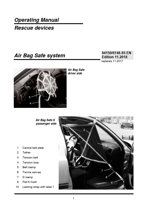
Operating Manual Rescue devicesreplaces 11.2017Air Bag Safe driver sideAir Bag Safe II passenger side1 Central belt plate2 Tether3 Tension belt4 Tension loop 5Belt clamp 6 Trevira canvas 7 D clamp 8 Flat K hook10Lashing strap with label 1Air Bag Safe system2 13410678584150/6148-85 EN Edition 11.20181 General safety information1.1 The device has been built in accordance with state-of-the-art standards and the recognised safety rules. Nevertheless, its use may constitute a risk to life and limb of the user or of third parties, or result in damage to the device and to other material property.1.2 Only use the device in a technically perfect state and according to the intended purpose, in a safety and risk-conscious manner, in accordance with the Operating Instructions. In particular, eliminate (or have eliminated) any faults which can impair safety.1.3 The device is intended exclusively for the purpose indicated in the Operating Instructions. Any further or different use shall not be considered proper. The manufacturer/supplier is not liable for any damage resulting from inappropriate use. The user bears sole responsibility for such use.Operation of the device in accordance with its designated use also includes compliance with the instructions set out in the Operating Instructions and compliance with the inspection and maintenance requirements.1.4 Ensure sufficient lighting during work!2 Organisational measures2.1 The Operating Instructions must always be at hand at the place of use of the device!2.2 In addition to the Operating Instructions, observe and use the generally valid legal and other binding regulations for accident prevention and environmental protection!In particular, this includes the wearing of work or protective clothing, a protective helmet with visor or protective goggles and protective gloves.2.3 Only persons who have received appropriate safety training are permitted to use the device, as otherwise there is a risk of injury.2.4 Observe all the safety instructions and hazard warnings on the device! Make sure that safety instructions and hazard warnings displayed on the device are always complete and perfectly legible.2.5 Do not make any changes, additions or conversions to the device without the approval of the manufacturer.2.6 Comply with the prescribed periods for recurring tests/inspections, along with those stated in the Operating Instructions.2.7 Ensure the correct disposal of all the packaging materials and dismantled parts.3 Appropriate use3.1 Driver Air Bag SafeThe Driver Air Bag Safe is designed as a protective device against unchecked triggering of the driver airbag after traffic accidents.3.2 Passenger Air Bag Safe IIThe Passenger Air Bag Safe II is designed as a protective device against unchecked triggering of the passenger airbag during emergency operations after traffic accidents.4 Description of Air Bag Safe, driver side4.1 The Air Bag Safe system consists of three separate beltmeshes for use on steering wheels of different diameters:- For steering wheel diameters of 350 - 390 mm,- For steering wheel diameters of 400 - 450 mm,- For steering wheel diameters of 430 - 500 mm.4.2 Each belt mesh consists of a central belt plate (1), to whicheight belts (2) are sewn in a star arrangement. The tensioningbelt (3) with tension loop (4) is used to fasten the belt mesh to thesteering wheel. A belt clamp (5) with automatic locking is used to fixthe tensioning belt before lashing.5 Structure of the system5.1 Preparatory measures5.1.1 A deformed steering wheel rim is no longer able to accept the forces safely when the airbag triggers and should thus always be checked for damage before using the Air Bag Safe. If there is visible steering wheel damage, we advise against using the Air Bag Safe!5.1.2 Ensure that the Air Bag Safe being used has a diameter suitable for the steering wheel size (see Point 4.1).5.2 Place the belt mesh over the steering wheel rim and pull the tension loop of the tension belt behind the steering wheel through the belt clamp. Centre the belt system on the steering wheel and fix it through as firm tightening of the tension belt as possible. Ensure as central a position as possible compared to the steering wheel / airbag!5.3 Even if the car battery is disconnected, leave the belt mesh for at least one hour in the lashed position (possible risk of late triggering!).5.4 Safety instruction:A belt mesh which has taken up a triggered airbag must always be replaced, as an invisible stretching of the material may occur.6 Structure of the systemAfter the safety time has elapsed, release the tension belt behind the steering wheel (open the belt clamp) and carefully remove the belt mesh from the steering wheel.7 8Fig. 197 Description of Air Bag Safe, passenger sideThe passenger airbag retention system is made up of a high-resistance Trevira canvas (6) with sewn-on horizontal and diagonal belts (2), onto each of which a D clamp (7) is sewn. Additional accessory:A lashing belt (10) with the code 1, with flat K hooks (8) at the ends.Four identical belts (11), a flat K hook (8) and an S hook (9) at the ends of each. To tauten each belt (10 and 11), the belt clamp (5) has a tension loop (4).8 Structure of the system8.1 Fastening around the A post and windscreen (see cover sheet)Hang the lashing belt (10) with code 1 at the top left or right in the D clamp (7) using the flat K hook (8), place it over the A post and windscreen and insert it on the other side. Tension it slightly using the belt through the belt clamp (5).Attach 2 belts (11) in the lower D clamp (7) using the flat K hook (8), run it to the front wheel rims and attach the S hook (9) in the individual front wheel rims (see Fig. 2). Align the canvas (6) and tension all the belts (10 and 11) using the belt clamps (5).8.2 After disconnection of the A post and roofAttach 4 belts (11) with the K hook (8) to the upper and lower D clamps (7) (see Fig. 1), run them to the front wheel rims and insert each S hook (9) into the rim (see Fig. 2). Align the canvas (6) and tension all the belts (11) using the belt clamps (5).8.3 Safety instruction:8.3.1 With a cabriolet, proceed as described under 8.2.8.3.2 Even if the car battery is disconnected, leave the lock for at least one hour in the lashed position (possible risk of late triggering!).8.3.3 A passenger airbag retention system which has taken up a triggered airbag mustalways be replaced, as an invisible stretching of the material may occur.59 78g h t 2018 L U K A S H y d r a u l i k G m b H9 Structure of the systemAfter the safety time has elapsed, release the belt clamps, disengage the S hooks and flat K hooks and carefully remove the canvas from the vehicle interior.10 Maintenance and service10.1 The devices can be used time and again, apart from in the case described under 5.4 and8.3.3. The maximum period of use is 10 years. After the maximum period of use has elapsed, the system must be replaced.10.2 The device must be protected against: Heat and open flames, chemicals, oils, fuel, etc. 10.3 Only remove soiling with mild household cleaning agents in the doses prescribed by themanufacturer. Then, clean the device well.10.4 The device must be stored in the intended case in a dry location, away from sources ofheat (max. storage temperature 80°C) and must be protected against direct sunlight or other ultraviolet radiation.10.5 Testing: Test at least once annually for flawlessness/completeness.11 RepairThe user may not carry out any repairs on the belt mesh. Please contact your authorised dealer or Customer Service. The address of the Customer Service department is: LUKAS Hydraulik GmbH , Weinstrasse 39, 91058 Erlangen; Postfach 2560,91013 Erlangen, Germany; Customer Service Tel.: +49 9131 698-338; Fax: +49 9131 698-353. HURST Emergency Products 711 N. Post Rd. • Shelby, NC 28150, USA TEL: +1(704) 487-6961 • FAX: +1(704) 482-7712 • LUKAS Hydraulik GmbHA Unit of IDEX CorporationWeinstraße 39, D - 91058 Erlangen • Germany Postfach 2560, D - 91013 Erlangen • GermanyTelephone +49 9131 698-0 • Telefax +49 9131 698-394 E-mail:*************HURST Emergency ProductsA Unit of IDEX Corporation 711 N. Post Rd.Shelby, NC 28150, USATEL: +1(704) 487-6961 • FAX: +1(704) 482-7712 。
应急通信指挥车方案讲解

应急通信指挥车技术方案目录第一章综述................................................................................................................................ - 1 -1.1 设计思想....................................................................................................................... - 1 -1.2 设计原则....................................................................................................................... - 3 -1.3 建设目标....................................................................................................................... - 3 -1.4 主要功能....................................................................................................................... - 4 -1、通信功能................................................................................................................ - 4 -2、图像采集、处理和传输功能................................................................................ - 4 -3、广播功能................................................................................................................ - 4 -4、照明功能................................................................................................................ - 4 -5、会议功能................................................................................................................ - 4 -6、供配电功能............................................................................................................ - 4 -第二章总体设计........................................................................................................................ - 6 -总体框架和总体拓扑示意图.............................................................................................. - 6 -2.1 无线图像传输系统....................................................................................................... - 7 -2.1.1 TFDM单兵式/密拍式无线图像传输设备传输流程........................................ - 7 -2.1.2 TFDM车载式无线图像传输设备传输流程................................................... - 10 -2.1.3 便携式3G公网无线图像传输设备传输流程 ............................................... - 12 -2.1.3 车载式3G公网无线图像传输设备传输流程 ............................................... - 15 -2.2 照明系统..................................................................................................................... - 18 -2.4 供配电系统................................................................................................................. - 20 -2.4.1 发电机.............................................................................................................. - 21 -2.4.2 APC不间断电源在线式5KV(C3KS)........................................................ - 22 -2.4.3 配电系统设计.................................................................................................. - 23 -2.5 安全警示系统........................................................................................................... - 23 -2.6 其他及辅助系统......................................................................................................... - 23 -2.6.1 广播系统.......................................................................................................... - 23 -第三章车辆改制...................................................................................................................... - 26 -3.1 原车外观与参数......................................................................................................... - 26 -3.2 外观效果图................................................................................................................. - 26 -3.3 总体布局图................................................................................................................. - 27 -3.4 整车配重..................................................................................................................... - 28 -3.5 设备减振..................................................................................................................... - 28 -3.6 系统的可维修性......................................................................................................... - 28 -3.7 设备及人员安全......................................................................................................... - 28 -3.8 电磁干扰(EMC)的解决 ........................................................................................ - 29 -3.9 车内装饰..................................................................................................................... - 29 -3.10 表面处理................................................................................................................... - 30 -3.11 车辆密封................................................................................................................... - 30 -3.12 隔音隔热................................................................................................................... - 30 -第四章设备配置列表......................................................................................错误!未定义书签。
红杉分时四驱正确操作方法

红杉分时四驱正确操作方法
红杉分时四驱(RSFS)是一种四驱车辆系统,可以在不同的路面和条件下提供更好的驱动力和控制性能。
以下是红杉分时四驱的正确操作方法:
1. 了解分时四驱系统的工作原理:红杉分时四驱系统通过一台中央差速器将动力传输到前后两个驱动轴上。
在正常行驶时,动力分配为前后轴之比为40:60,以提供更好的操控稳定性。
如果后轮打滑或失去牵引力,分时四驱系统会自动将动力转移到前轴,以提供更好的牵引力。
2. 切换到四驱模式:根据车辆上的说明,找到切换分时四驱模式的按钮或开关。
通常,这个按钮/开关可以在车辆内部的中控台上或驾驶员座椅旁边的位置。
按下按钮/切换开关,将车辆切换到四驱模式。
3. 调整驾驶行为:在四驱模式下,车辆的操控性能会有所不同。
由于红杉分时四驱系统能够提供更好的牵引力,所以可以更加自信地行驶在湿滑、泥泞或崎岖的路面上。
然而,仍然需要谨慎驾驶,并根据路况和速度做出适当的反应。
4. 切回两驱模式:在需要的时候,可以将车辆切换回两驱模式。
这可能是因为路面干燥,或者在高速公路上行驶。
再次按下切换按钮/开关,将车辆切换回两驱模式。
5. 定期保养和检查:分时四驱系统是车辆的关键部分之一,因此需要定期进行
保养和检查。
定期检查润滑油、传动系统和其他相关部件的状况,并根据制造商的建议进行更换。
总的来说,正确操作红杉分时四驱系统需要了解其工作原理,适应不同的驾驶条件,适时切换模式,并进行定期保养和检查。
请注意,以上步骤仅供参考,请根据您所驾驶的具体车辆和制造商提供的操作指南进行操作。
应急指挥车操作流程

应急通信指挥车操作流程开机流程1、停车停车位选择地势平坦,无高空障碍物,无强磁干扰,无影响卫星通信的位置,车头面向南方(有利于卫星対星)。
2、打开车门和通风在车辆停稳后,打开车辆后门,检查油料是否充足,检查后边发动机和其它设备是否正常,冷却液是充足。
在车辆行驶过程中,由于关闭了车门,应打开车厢侧边通风板和通风风扇,车厢内在控制平台两侧窗户应打开通风,避免发电机废气造成一氧化碳中毒。
3、打开电源电源控制中心面板(1)启动电源控制中心,启动发电机。
(2)打开UPS,在UPS灯闪烁30s后,再打开总电源开关。
4、打开车尾仓设备尾仓设备主控面板图(1)打开直流设备开关,打开支撑系统开关、打开倒伏器开关。
(2)开启支撑系统开关-,进行群支操作,在右侧4个显示器数据归零后,将群支开关拨回停止位。
(3)开启倒伏器开关,将倒伏器1(天线)和倒伏器2(天线)立起后,将升降开关拨回停止位。
(4)升起车顶摄像机立杆,通过驾驶室摄像机立杆控制器,或者车厢车载控制台摄像机立杆遥控器进行控制,升起车顶摄像机立杆。
5、开启卫星天线各设备主电源开关(1)在车厢控制平台,打开设备主要开关(机柜1、机柜2、机柜3、充电机和直流开关),注意:在卫星天线锁定卫星后,再打开VSAT高功放开关进行卫星通信。
卫星天线控制器面板(2)打开天线控制器,点击“确定“按钮,选择“自动寻星“,开始寻星,在设备锁定卫星后,打开VSAT高功放开关。
6、打开主控计算机在卫星寻星过程中,可以打开控制台下的主控计算机开关,启动主控计算机。
7、打开其他设备打开液晶电视和会议系统,液晶电视和会议系统由两个遥控器分别控制。
其中电视输入源输入3是AV信号,输入6是VGA信号,远程电视电话会议通过输入6VGA信号进行设置,主界面为会议系统控制界面。
通过遥控器”√”进行选择,选择拨号地址为10.253.0.*地址。
8、视频和音频输入的切换通过视频矩阵实现,操作命令为“输入端口+ 视/音类型(设备按钮audio/vidio)+输出端口+end键+enter键(确定)“。
枫叶80V汽车应急救援手册说明书

• 如有必要,使用拖车的提升装置提升 车辆。
19
2
产品信息
关于枫叶80V汽车
本手册相关的重要信息
本车为纯电动车辆,通过驱动电机提供行驶 动力。
为了更好地理解本手册中的内容,您需要了 解有些重要信息。
1
车辆配备两种不同类型的蓄电池。一种是与 常规车辆相同的12V蓄电池,另一种是驱动 车 辆 行 驶 所 使 用 的 锂 离 子 动 力 电 池 (高 压)。动力电池封装在车辆底部。 在无法快速更换高压电池的情况下,可以使 用充电桩对动力电池进行充电。
1. 取出行李箱内的牵引环(参见第8页)。 2. 按照下图所示,打开前部或后部牵引孔
盖。 3.
4. 然后将牵引环旋入牵引钩螺纹导套内, 确保牵引环完全拧紧。
5. 使 用 完 后, 拆 卸 牵 引 环, 放 回 储 存 位 置。重新装好牵引孔盖。
在某些情况下,牵引环可用于将车辆 拉上平板拖车。
• 车辆的位置和离地间隙决定了车辆是 否能用牵引环拉上平板拖车。
10
安全标志信息
安全标志
序号
安全标志名称
1
带高压电警告标志
安全标志信息
1
安全标志图样
安全标志释义
切勿触碰高压部件, 有危险!
2
高压部件警告标志
切勿触碰高压部件, 有危险!
3
电池包标签
电池包基本信息
4
高压线束
高压线束线色:橙色
11
安全标志信息 12
应急处置程序信息
准备项目
防护设备
1
当接触或维护高压系统时,应该正确使用以下保护设备。 • 处理高压系统时,请戴上安全眼镜。 • 接触高压部件时,请戴1000 V绝缘手套。 • 操作高压系统时,请使用绝缘工具。 • 准备绝缘防护钩。 • 使用适用于锂离子电池的灭火器(如干粉灭火器)。 • 请勿单独作业,遵循两个人的原则,如果出现事故你可能需要帮助。
雷克萨斯LM四座车型产品说明书
*LM 四座车型专属配备 ,具体配置以实车为准。 **为丰田汽车(中国)投资有限公司提供 ,由雷克萨斯中国经销商提供安装服务的中国产纯正精品 。 详情请致电当地雷克萨斯中国经销商垂询。
旗舰风范,大气卓然
外展恢弘,皆是旗舰气象;匠心内蕴,营造大美之境。 采用雷克萨斯全新电气化美学语言,精致的一体化纺锤形车身, 搭配流畅的车身线条,与前格栅的空气动力学造型相得益彰, 动静之间,尊荣尽显。
跳转至
开篇 尊荣外观 雅逸内室 挚感科技 智能安全 智行互联 服务
图片展示为 LM 四座车型 ,该车型即将上市,敬请期待 ,具体配置以实车为准。
图中屏幕显示仅用于展示说明 ,实际显示内容会根据不同操作有所不同。
Tazuna 缰绳概念座舱 12.3 英寸全液晶仪表盘 全新多媒体系统LEXUS Interface *全彩抬头显示器HUD带方向盘按键触摸示踪功能 贯穿座舱顶部的操控面板 第二排掌上无线多功能控制面板 整车智能交互体验 后排一键电动开合侧滑门功能 电动行李箱背门开关 遮阳帘控制全面电动化
以上所示图片仅供参考 ,中国大陆地区销售的具体车型配置 ,请以实车为准。
动态雷达巡航控制系统DRCC 带全速域跟车功能
车道偏离警示系统 LDA /智能车道循迹系统 LTA
驾驶员状态监测系统 DMC 带人脸识别功能
预判式主动驾驶辅助系统 PDA
驾驶员状态监测系统 DMC 带人脸识别功能
预碰撞安全系统PCS 带紧急转向辅助功能ESA 远光灯自适应控制系统AHS 动态雷达巡航控制系统DRCC带全速域跟车功能 车道偏离警示系统LDA *智能车道循迹系统LTA 预判式主动驾驶辅助系统PDA 紧急驾驶停止系统EDSS 驾驶员状态监测系统DMC 带人脸识别功能
4、3G车载终端操作手册详解

3G车载终端操作手册华平信息技术股份有限公司目录一、3G卫星车终端使用场景 (4)1.1车载机柜式 (4)1.2临时指挥中心 (5)1.3单兵背负方式 (6)二、3G卫星车终端设备连接 (7)2.1终端界面介绍 (7)2.2终端设备连接图 (12)2.3显示设备连接 (12)2.4音频输入输出连接 (13)2.5视频输入连接 (14)2.63G网络连接 (15)2.7终端电源连接 (16)2.8设备安装连线图 (17)三、3G卫星车终端操作 (19)3.1开机设置流程图 (19)3.2登录界面 (20)3.3系统登录设置 (21)3.43G拨号设置 (23)3.5以太网设置 (25)3.6网络测试 (26)3.7视音频设置 (27)3.8显示设置 (29)3.9进入会议 (30)3.10注意事项: (35)3.11重启或关闭终端 (35)四、终端维护 (36)4.1环境要求 (36)4.2注意事项 (37)4.3常见故障排查 (38)一、3G卫星车终端使用场景3G图像传输系统终端设备采用的是华平公司3G车载终端,该终端支持在灭火救援指挥现场不同环境下的使用,满足公安消防各级指挥中心对灭火救援现场图像及声音传输需求。
1.1车载机柜式3G卫星车终端可以安装在车辆标准机柜中。
终端提供标准机柜耳片,占用机柜2U高度。
与车辆上的音频设备、图像设备、显示设备等进行对接,成为车载设备的一部分。
1)用户环境准备:①通讯指挥车需要提供稳定的220V电源,供3G终端设备使用。
②通讯指挥车上已经装有摄像机,需要使用此摄像机时,需额外准备摄像机的视频线和控制线各一根。
③如要将终端的声音输入输出与指挥车内音响系统连接,需要准备到终端输入输出3.5接口的音频线各一根。
④如要将终端的显示输出与指挥车内显示器上,需要准备到终端的视频输出接口VGA或HDMI线一根。
⑤通讯指挥车要准备标准机柜托盘一个,并且机柜里空出2U高度空间便于终端安装。
2022年 Lexus 轿车系列 Sunroof 操作说明书

Sunroof (LS/GS) To open or close the sunroof, push and hold the switch. Release the switch when the sunroof reaches the desired position.Do not hold the switch on after the sunroof has fully opened orclosed, or you may damage the sunroof motor.Do not allow any part of your body to extend through the sunroof while the vehicle is in motion. In the event of a collision or sudden application of the brakes, severe personal injury couldresult.To avoid the possibility of injury while closing the sunroof, never allow any part of your body to extend through the opening.CAUTION:Operating the sunroof in severe cold or when it is covered with snow or ice may cause damage to the sunroof.SunshadeAs well as the sunroof, there is a sliding sunshade which you can adjust to let in light with the roof closed, or to block out light entirely. The sunshade automatically opens as you open the sunroof.(cont'd) CloseOpenPOP-UP WINDDEFLECTORSUNSHADESunroof (cont'd)If the Sunroof Won't CloseThe sunroof can be closed manually,if the control switch will not close it.1. Remove the round plug near the rear center of the headliner.2. Insert the sunroof wrench (from the tool kit) into the socket.3. Turn the wrench until the sunroof seats in the closed position.4. Replace the plug.Remove plugMaintenancePeriodically pour a little water down the drain holes to make sure they are not plugged. If they are free, water should drop on the ground behind each front wheel.CAUTION:Do not put weight on the sunroof or force it open or closed, you may damage the mechanism.SOCKETDRAIN HOLEStereo Sound System (LS/GS)(LS)(GS)ON/OFF Switch On the LS model:Turn the switch clockwise to turn the unit on; turn it counterclock-wise to turn the unit off.On the GS model:Push the button to turn the unit on; push it again to turn the unit off.NOTE:The antenna will rise or retract automatically when the unit is turned on or off. It will also retract automatically if the ignition isswitched off.Volume Control On the LS model:Turn the ON/OFF switch clockwise to increase volume and counter-clockwise to decrease volume.On the GS model:Push the switch up to increase volume and down to decrease volume.(cont'd)Bass ControlTreble ControlBass ControlTrebleControlStereo Sound System (cont'd)Balance ControlBalances sound between left and right speakers.NOTE:When the headlights are on, the radio panel illumination is on, even if the radio is turned off.The panel lighting can be turned off by first pushing the Balance Control button to its out position and then pulling it out slightlyfurther.Fader ControlBalances sound between front and rear speakers.AM/FM Band SelectorPush to select AM or FM band. The corresponding band indicatorwill light.Manual TuningPush the button to tune to a lower frequency station.Push the button to tune to a higher frequency station.NOTE:If you hold either button for more than half a second, the tuning frequency will count up or down rapidly.Radio Operation Frequency Display (LS)(GS)FrequencyDisplaySeek TuningEach time you push this button up or down, the tuner will automatically seek the next higher or lower frequency station.Preset Station Selection1. Make sure the Band Selector is on the band you want ... AM orFM. Then, find the station you want by Manual Tuning or Seek Tuning.2. Press and hold one of the Preset Buttons.3. In a few seconds, a beep will sound and the light in the button will come on. The station is now preset in the memory. You may preset 1 AM and 1 FM station per button, (total, 6 of each on the4. LS model and 8 of each on the GS model).You can tune to a preset station by pushing its corresponding preset button.NOTE:(On the GS model)The Auto Select Button must be off before the Preset Station Selection can be used.Auto Select Button (GS only)If you are visiting a new broadcast area, you can quickly enter into memory the stronger stations in that area by simply pushing the Auto Select Button. The radio will then automatically scan both the AM and FM bands and temporarily memorize up to eight stations in each. With the Auto Select Button on, these stations can then be tuned by pushing the preset buttons. Manually-preset stations remain memorized for use when you return to your normal broadcast area, but are only selectable with the Auto Select Button off.Stereo IndicatorThis lights up when a FM broadcast in stereo is being received. It will flash when the signal strength diminishes. If it flashes, good stereo reception cannot be expected. Stereo reception is available only for FM stereo broadcasts, not for AM stereo broadcasts.(cont'd)Stereo Sound System (cont'd)Tape Operation(GS)Tape Direction IndicatorWith the cassette inserted "A " side up, the indicator ( ) will light when the "A " side is playing; the indicator ( ) will light when the "B" side is playing.Program Selector (PROG)Push to change the direction of tape play.Auto Reverse Feature: The tape direction automatically reverses when the end of the tape is reached in play or FF mode and plays the other side.(LS)Fast Forward/Rewind (FF/REW)Note which Tape Direction Indicator is lighted, then push the appropriate button to rapidly wind the tape in the same direction (FF) or in the opposite direction (REW).Play (PLAY)Push the PLAY button (indicator on) to resume tape play and stop rewind or fast forward operation.Repeat Button (REPEAT)Push the REPEAT button (indicator on) to return to the beginning of a song or section of programming and repeat its play. Push the button again (indicator off) to cancel the repeat function and resume normal play.Dolby ® Noise Reductio n ( )Push when playing tapes recorded in Dolby NR (the Dolby NR indicator will light). Push again when playing tapes not recorded in Dolby NR. Use of the wrong setting will affect high frequency response.NOTE:The Dolby NR circuit will not operate during radio reception.Dolby noise reduction system is manufactured under license fromDolby Laboratories Licensing Corporation. "Dolby" and the double-D symbol are trademarks of Dolby Laboratories Licensing Corporation.Skip ButtonThe circuit senses silent passages between songs or programs on a tape. Push upward to automatically advance to the beginning of the next song, or downward to return to the beginning of the song just played.NOTE:Tapes that contain short silent passages between songs, a high level of noise between songs, or silent passages within a song may not be suitable for this function.Metal Indicator (METAL)Most metal or CrO 2 cassettes are coded with slots on their back edge. If such a cassette is inserted, the player will detect the slots and automatically switch to the proper equalization for full enjoyment of metal/CrO 2 tapes. The indicator light will go on when coded cassettes are played.(cont'd)Stereo Sound System (cont'd)Eject (EJECT)Push this button to stop and eject the tape.Ignition Key-OFF Eject: The cassette being played will be automat-ically ejected when the ignition or the unit is turned off.NOTE:When one side of the tape ends, "Auto-Reverse" will automatically begin playing the other side, therefore, you must push the eject button to stop or remove the tape.CLEAN Indicator LightAfter 50 hours of cassette tape play, the light will come on as a reminder to clean the tape heads. If the light comes on and the tape heads were not cleaned at the recommended 30 hours of usage (see maintenance section below), they should be cleaned immediately. To reset, push the indicator for a minimum of five seconds until the light goes off.MaintenanceThe head in the cassette tape player can pick up dirt or tape deposits each time a cassette is played. The result is low or "muddy" sound from one or both channels, as if the treble tone control were turned all the way down. To prevent this, you should periodically clean the head with a commercially available cleaning cassette.As preventive maintenance, clean the head about every 30 hours of use. If you wait until the head becomes very dirty (noticeably poor sound), it may not be possible to remove all deposits with a simple cleaning cassette.The use of 120 minutes tapes is not recommended.CAUTION:Storing cassettes out of their cases, or touching the magnetic tape with your fingers will increase the amount of dirt that gets to the tape head. Using low-quality "off-brand" tape will increase the amount of tape deposits that get on the head. Both of these practices may eventually lead to damage of the head and playing mechanism.Gasoline For proper operation of your car's emission controls, your engine is designed to use unleaded fuel only.CAUTION:Using leaded or even low-lead gasoline could damage some of your emission controls, and also void their coverage under the emission controls warranty.Use gasoline from pumps labeled unleaded, with a pump octane number of 86 or higher. The pump octane number is an average of the Research (R) octane and Motor (M) octane numbers. Use of a lower octane gasoline can cause persistent, heavy "spark knock" (a metallic rapping noise), which can lead to engine damage if severe.CAUTION:If you notice steady spark knock while holding a steady speed on a level road, try changing brands of gasoline. If the spark knock persists, consult your Acura dealer. Failure to do so is considered misuse, and misuse is not covered under the New Car Warranty.Occasionally you may notice light spark knock while accelerating or driving up hills. This is no cause for concern, it simply means your engine is running at its most economical.Gasoline Containing AlcoholIf you decide to use a gasoline containing alcohol ("gasohol"), be sure its octane rating is at least as high as that recommended for unleaded gasoline. There are two types of "gasohol": that containing ethanol, and that containing methanol. Do not use gasohol that contains more than 10% ethanol. Do not use gasoline containing methanol (methyl or wood alcohol) that does not also contain cosolvents and corrosion inhibitors for methanol. Never use gasoline containing more than 5% methanol, even if it has cosolvents and corrosion inhibitors.(cont'd)Gasoline (cont'd)NOTE:Fuel system damage or vehicle performance problems resultingfrom the use of such fuels is not covered under the new car warranties. The Acura Automobile Division cannot endorse the use of fuels containing methanol since evidence of their suitability is as yet incomplete.Before purchasing fuel from an unfamiliar station, try to confirmwhether the fuel contains alcohol, of what kind, and how much. If you notice any undesirable operating symptoms after using a gasoline that contains alcohol; or one that you think contains alcohol, switch to an unleaded gasoline as recommended on page55.Operation In Foreign CountriesIn order to comply with U.S. Federal Emission Regulations, you must use unleaded fuels of the recommended octane rating. These fuels may not be available in other countries. If you intend taking your car outside the U.S. or Canada, write to the Acura Automobile Division (stating the year and model of your car) at the address below for information regarding modifications you may need to have done.Acura Automobile DivisionCustomer Relations Office.1919 Torrance Blvd.Torrance, CA 90501-2746。
移动指挥车完整

工作结束后收拢
• • • • • • • 按UPS面板关闭UPS 收起电缆盘,绑扎固定在后舱指定位置 收起接地钎,绑扎固定在后舱指定位置 随车工具绑扎固定 储物柜内设备绑扎固定 收回支撑腿 关闭外接口板,后舱门及车门
谢谢!
应急指挥车 快速操作流程
电信科学技术第一研
• 检查车况(油量,轮胎气压,灯光,喇叭,车辆制动,发电机状况) • 检查车顶(天线和避雷针搭扣是否锁定牢固,车顶暴露在外的部件有 无出现螺栓螺母松动) • 检查各种随车工具是否带齐 • 检查终端设备是否带齐,是否电量充足 • 检查车内放置在桌面、储物柜及后舱的设备是否绑扎牢固 • 车辆启动前,如驾驶台左侧支腿收回指示灯亮,请检查支撑腿是否收 回到位
车辆到达后展开
车辆到达后展开
• 车辆停放在合适位置(需考虑无线覆盖范围影响、微波/卫星通信影 响,避开强风口处等因素;地面平整、坡度小于5度,周边可以打地 钎) • 撑起支撑腿 • 车辆接地(包括工作接地与防雷接地,两地钎相隔距离需>10米,接 地电阻<10Ω ) • 解除车顶天线和避雷针固定搭扣 • 供电(有条件的情况下接入市电,无市电启动发电机,同时合上市电 与发电机的输出空开) • 按顺序合上以下空开:空调,塔基,中控,其它设备空开按需要合上
车辆到达后展开
• 按空调面板开关开启空调(改善操作环境 保证设备正常运行) • 使用中控触摸屏,操作升降杆升起,顺序依次为:天线—避雷针—升 降杆 • 按工作需要开启车上其他设备空开 • 检查各设备功能是否正常(终端呼叫,视频,声音等是否正常) • 开始正常工作
工作结束后收拢
工作结束后收拢
• • • • • • 有序关闭车上各设备空开(工控机、SAC需手动操作关闭) 各种终端设备关闭并收藏入储物柜 升降杆系统按天线-避雷针-升降杆的顺序收拢复位 天线和避雷针搭扣锁定 按空调面板关闭空调 依次关闭各空开,顺序为:各业务设备、空调、塔基、UPS输出、发 电机输出、市电输出 • 按发电机面板关闭发电机
通讯指挥车操作流程

通讯指挥车操作流程一、概述通讯指挥车是一种特殊的车辆,在应急救援、抢险救灾等工作中起到重要的作用。
本文将介绍通讯指挥车的操作流程,以帮助操作人员正确、高效地使用该车辆。
二、准备工作1. 检查车辆:(1) 外观检查:检查车身是否有明显损坏、腐蚀等情况;(2) 内部设备检查:检查车内通讯设备、电源系统等是否正常;(3) 燃油检查:检查燃油是否充足,如不足应及时加油。
2. 准备设备:(1) 通讯设备:确保通讯设备完好并已正确设置频率、音量等参数;(2) 导航设备:确保导航设备已更新地图数据,并能正常使用;(3) 照明设备:夜间或恶劣天气下,准备照明设备以确保工作区域的充分照明;(4) 工具箱:准备常用维修工具,以备不时之需;(5) 工作记录表:准备记录表以记录重要信息。
三、操作流程1. 启动车辆:(1) 检查刹车:踏下刹车踏板,确认刹车工作正常;(2) 点火启动:插入钥匙,扭动启动开关,启动发动机;(3) 加速预热:启动后,根据气温情况,适当加大油门并保持数分钟,使发动机预热。
2. 通讯设备检查:(1) 打开通讯设备:确认通讯设备电源已打开;(2) 频率设置:根据工作需要,设置合适的频率,并调整音量适合操作环境;(3) 信号测试:通过测试检查通讯设备是否正常工作,包括收发信号是否清晰有力。
3. 路线规划:(1) 导航设置:根据工作需要,输入目的地坐标或者选择已保存的路线;(2) 路线选择:根据实际道路状况,选择合适的道路路径;(3) 行车安全:遵守交通规则,保持车距,确保行车安全。
4. 工作过程中的注意事项:(1) 保持关注:持续关注通讯设备,确保及时收发信息;(2) 记录重要信息:在工作记录表上记录相关信息,如接到指令、遇到困难等;(3) 沟通协调:与其他车辆、人员保持良好的沟通协调,确保工作的连贯性和高效性;(4) 维护车辆:在合适的时间和地点,对车辆进行维护保养,确保车辆的正常运行。
四、结束工作1. 关闭设备:(1) 关闭通讯设备:确保通讯设备已关闭,以节约电源;(2) 关闭导航设备:关闭导航设备并断开电源。
通信指挥车使用技巧

通信指挥车使用技巧通信指挥车是一种通信控制车辆,其主要用途是在野外作战或重要活动中,提供一种流动的、即时的通信指挥平台。
为了确保通信指挥车的正常使用,以下是一些通信指挥车使用技巧。
首先,通信指挥车的操作人员需要熟悉车辆的使用说明书和操作手册。
在使用通信指挥车之前,必须对车辆的操作进行详细的了解,包括车辆的启动、行驶、停车、关机等操作步骤。
只有熟练掌握车辆的操作,才能更好地发挥通信指挥车的功能。
其次,通信指挥车的操作人员需要具备良好的电子设备操作技能。
通信指挥车通常配备了各种通信设备,例如对讲机、无线电等,操作人员需要了解这些设备的使用方法。
对于复杂的通信设备,操作人员还需要进行专门的培训,以确保能够熟练掌握设备的使用。
第三,通信指挥车的操作人员需要具备一定的通信技巧。
作为通信指挥车的使用者,操作人员在与其他人进行通信时,需要注意一些细节。
例如,使用对讲机进行通信时,要注意语音的清晰、准确、简洁,不要出现模糊、含糊或冗长的说话方式。
同时,对于不同的交流对象,操作人员还需要根据实际情况选择适当的沟通方式,例如使用正式或非正式的用语。
第四,通信指挥车的操作人员需要具备一定的团队协作能力。
在使用通信指挥车时,通常需要与其他人员进行密切配合。
操作人员需要与其他车辆或指挥中心进行沟通,确保信息的及时传递和准确理解。
因此,操作人员需要具备团队协作的能力,能够在紧急情况下高效地与他人合作,共同完成任务。
最后,通信指挥车的操作人员需要时刻保持警惕,注意安全。
在使用通信指挥车时,操作人员需要注意道路或作战环境的安全状况,遵守交通规则和军事纪律。
特别是在特殊环境下,如夜间或恶劣天气下,操作人员需要更加谨慎,确保车辆和人员的安全。
总之,通信指挥车的使用技巧包括熟悉操作手册、掌握电子设备操作技能、具备良好的通信技巧、具备团队协作能力和保持警惕。
只有运用这些技巧,操作人员才能更好地使用通信指挥车,为作战或重要活动提供及时、准确的通信支持。
应急通讯指挥车方案
应急通讯指挥车方案一、引言应急通讯指挥车(Emergency Communication Command Vehicle,简称ECCV)是一种专门应对突发事件的移动通信设备。
它以快速部署、强大的通信能力和协同指挥为特点,能够提供紧急救援和灾害恢复过程中所需的通信支持。
本文档将详细介绍应急通讯指挥车的功能和实施方案。
二、背景随着突发事件的频繁发生,现有的通信设备常常无法满足应对突发事件的需求,导致信息交流不畅和协调困难。
应急通讯指挥车的出现填补了这一空缺,成为重要的灾害应急技术手段。
三、功能与特点1. 快速部署应急通讯指挥车具备快速部署的特点,可以迅速到达灾区并立即提供通讯支持。
通过车载通信设备和卫星链接,及时与指挥中心和其他救援单位建立通信链路,实现联动指挥和信息共享。
2. 强大通信能力ECCV内置多种通信设备,包括无线电、卫星通信、移动网络等,可以实现多种通信网络的切换和融合。
这使得ECCV具备更好的抗干扰能力和更广泛的通信范围,能够在灾害现场建立稳定的通信网络。
3. 协同指挥应急通讯指挥车作为一个移动指挥中心,能够与各救援单位实现实时协同指挥。
通过车载终端、视频监控和指挥系统,ECCV能够远程监控现场情况、制定救援方案和指挥救援行动,提升救援效能和应急响应速度。
4. 多功能配置ECCV除了通信设备外,还可以配备医疗设备、供电设备、应急广播设备等,以满足不同应急情景的特殊需求。
这样的多功能配置能够在紧急情况下为救援人员提供更好的生活和工作条件,提高救援效率。
四、应急通讯指挥车实施方案1. 设备配置a. 通信设备•车载无线电台:用于与救援人员、指挥中心等建立实时联系。
•卫星通信终端:提供远程通信能力和数据传输。
•移动网络终端:利用移动基站建立本地通信网络。
•其他通信设备:如电话、对讲机等。
b. 指挥系统•车载指挥系统:用于指挥人员实时监控和指挥应急救援行动。
•视频监控系统:通过摄像头监控灾害现场情况,并实时传输给指挥中心。
长城汽车使用手册说明书
操作
介绍了钥匙、车门、车窗、座椅等车内装备的基本操作方法。
驾驶
介绍了车辆启动、换挡方法、仪表等驾驶相关内容。
视听系统
介绍了蓝牙电话、系统设置等视听系统相关内容。
安全性
介绍了车辆防盗系统、安全带等保护装置。
紧急情况
介绍了爆胎、蓄电池亏电等车辆故障的处理方法。
维护保养
介绍了车辆的日常检查以及定期维护保养的事项。
4
外观 A
B
C
DE
F
G
H
I
J
K
5
Ⓐ 货箱门把手 25 Ⓑ 高位制动灯 Ⓒ 车窗 28 Ⓓ 外后视镜 47 Ⓔ 前雨刮 54 Ⓕ 门锁 22
Ⓖ 倒车影像 93 Ⓗ 后组合灯 49 Ⓘ 充电口 33 Ⓙ 前组合灯 49 Ⓚ 侧转向灯 49
6
内饰
AB
C
D EF G
H
IJK
L MN
QO
7
Ⓐ 中控锁按钮 22 Ⓑ 灯光控制组合开关 49 Ⓒ 组合仪表 120 Ⓓ 雨刮控制组合开关 54 Ⓔ 中控面板开关总成 Ⓕ 换挡杆 87 Ⓖ 空调出风口 61 Ⓗ 车门内扣手 23
〉 谨慎驾驶:务必谨慎驾驶。随时注意路面 上其他驾驶员或行人的错误动向,以便及 时做出判断,防止意外事故的发生。
〉 专注驾驶:驾驶时务必全神贯注。任何分 散驾驶员注意力的事情,如调节控制按 钮、接打手机或阅读都可能引发碰撞事故 并导致您、车上的乘客以及其他人员严重 伤亡。
警告
禁止将儿童单独留在车内,也不要让儿童携 带或使用钥匙。 儿童可能会启动车辆或随意切换换挡杆挡 位。儿童玩耍车窗、天窗或车辆的其他设备 时也可能会伤害到他们自己。此外,车内温 度过高或过低,也可能会对儿童造成致命伤 害。
紧急救援功能模块使用说明书

紧急救援功能模块使用说明书测试使用浏览器版本为:windows10环境下Google Chrome 52.0.2743.116 m 版本浏览器注:所有打*号的为必填项一.救援中心配置1.打开:8003/#!/输入正确的用户名密码登录2.在左侧导航栏中找到并单击‘经销商’ ‘经销商列表’,找到需要配置救援中心的经销商,单击‘’按钮进入详细信息页面图 1图23. 进入页面将页面滑动到最底部找到救援设置如图3所示单击单独设置一套救援规则,可选择‘本机构需要开通独立的救援中心’和‘是否让用户主动寻找门店和附近救援车’(可二选一可全选)如图4所示配置完成后,单击‘提交’按钮即可注:【本机构需要独立开通独立的救援中心】必须配置客服电话【与上级经销商保持一致】含义如下:1.如果上级机构开通了【中心救援】,那么就由上级机构的救援中心负责救援事物2.如果上级机构没有开通【中心救援】,那么就没有中心救援功能图 3图 4二.新增救援车辆1.在左侧导航栏中找到并单击‘救援’—>‘救援车辆’,在出现的页面中单击‘新增车辆’按钮如图5图6-1所示,注:不能选择并查看到已出车的驾驶员。
已分配给其它车辆的驾驶员(未出车)若在新增车辆时被分配给了新增的救援车辆,则原先被分配的那辆车的驾驶员变为‘无驾驶员’联系电话变为空。
如图6-2所示。
图 5图6-1图6-22.填入相应的车辆信息,单击‘保存’按钮即可注:设备的imei号必须为操作时所选择的代理商所拥有的设备能拖车:代表救援车能将客户车辆运载到修理处,进行维修驾驶员的信息添加请往下翻阅图7三.驾驶员的添加管理1.驾驶员:可以指定本机构的任意一名员工为驾驶员(管理员请在‘设置’—>‘用户管理’页面,添加员工信息)如图8所示图82. 输入各项信息,单击‘提交’即可注:‘角色’的创建是在‘设置’—>‘角色管理’中进行创建的图9四.手动添加救援单注:等待救援:车主发出救援请求,生成救援订单,但并未分配救援人员和车辆正在救援:已分配救援人员和车辆进行维修完成救援:完成车辆的救援1. 当客服人员接到客户的救援电话时,请在左侧导航栏找到并单击‘救援’—>’救援中心’,如图10所示图102.单击‘新增救援单’按钮,如图11所示图113.填入来电的车主电话,点击‘查看车辆’,找到该车主所需要救援的车辆,单击并选中它,可以对救援的车辆信息进行修改。
- 1、下载文档前请自行甄别文档内容的完整性,平台不提供额外的编辑、内容补充、找答案等附加服务。
- 2、"仅部分预览"的文档,不可在线预览部分如存在完整性等问题,可反馈申请退款(可完整预览的文档不适用该条件!)。
- 3、如文档侵犯您的权益,请联系客服反馈,我们会尽快为您处理(人工客服工作时间:9:00-18:30)。
丰田红杉LTE应急指挥车使用说明
一、LTE应急指挥车应用总体说明
丰田红杉现场应急指挥通信车,完成现场4G无线网络覆盖,在对现场人员和车辆进行音视频指挥调度的同时,可以通过超短波电台(或通过3G、卫星、光缆等其他通信手段),同位于局端指挥调度中心进行音视频指挥调度连线。
为了满足用户的需求,提高指挥调度车的使用效率,实现特种指挥调度车辆在执行任务和平时办公时都可以使用,特设计了可拆卸式通信车组,进而实现:
1、执行任务时作为指挥调度车可实现超短波、指挥调度、单兵图像采集
和图像回传功能;
2、使用完毕后可将所有通信设备拆除,设备安装在防雨防震机箱内,平
常放置在库房;
3、平时办公时可以作为办公车辆正常使用,此次车辆的改装不会影响车
辆的任何使用性能;
4、需要应急时,可在短时间内将各设备安装到位。
二、拆除所有设备后车辆可用于办公时的状态
1、日常办公时丰田红杉车的状态
日常办公时,所有的指挥调度设备都不会放在车内,包括LTE设备、调度设备、室外射频单元RRU、UPS、发电机和其他附件,全是装箱放到库房里,同时天线升降杆、地脚支撑也是放在库房里面的。
改装后的丰田红杉车同改装前,从外观上几乎看不出任何变化。
车顶行李架安装了一个承载架,车尾下方固定了一个用于安装天下升降杆的安装梁,车内后备箱有个永久固定的车内安装板(车辆第二排后排座拆下,改装后不能再装上去了)。
日常状态照片(没有安装升降杆和车顶CPE和RRU)
2、红杉车内还固定的一些指挥调度用设备和结构,在车辆日常办公过程
中是取不下来的,包括3个显示屏(一个15寸的折叠屏和两个7寸的
头枕屏)、固定在车后排侧面的音视频接口面板、车底的电缆穿线孔等。
屏的照片及说明
接口面板照片及说明
电缆孔照片
3、LTE及其它设备的储存
在没有应急活动发生时,所有的指挥调度设备全是装箱放到库房里,分为LTE设备箱、调度设备箱、RRU箱、UPS、发电机、天线箱、附件箱、手机箱。
另外天线升降杆及地脚支撑也是放在库房里存放。
1)LTE设备箱
照片及说明
2)调度设备箱
照片及说明
3)车载UPS
照片及说明
4)汽油发电机
照片及说明
5)LTE天线箱
照片及说明
6)电缆及附件箱
照片及说明
7)手机箱
照片及说明
三、应急事故发生后,设备上车,运输状态
1、设备箱上车并固定
将LTE设备箱和调度设备箱上车,并用绑带固定;车载UPS上车并绑带固定;车载发电机(包括电源线辊子)上车并绑带固定;LTE圆筒天线上车绑带固定,电缆及附件箱上车绑带固定;手机箱上车。
按照安装步骤多照几张照片,再补上说明
2、天线升降杆安装
按照安装步骤贴照片(照片)并补上说明
3、车顶RRU和CPE或者短波天线的安装
照片及说明
4、车辆运输状态(应该注意的问题)
1)运输状态的照片
2)运输时的注意事项
四、车辆到达现场后,建立通信系统
1、将天线升降杆移动车侧后方,打开后车门,拿出LTE天线箱、馈线
及附件箱、发电机等
照片
2、进行LTE设备箱和调度设备箱之间线缆连接
照片及连线图
3、设备箱与车上的固定信号面板的电缆连接,设备箱与UPS的电缆连
接
照片及连线图
4、通过车底电缆孔穿电缆,连接发电机
照片
5、通过车底电缆孔穿电缆,连接车顶RRU和短波天线
照片
6、将LTE圆筒天线安装到升降杆上,并拧上6根馈线。
照片及连线图
7、关上后车门,摆正天线杆位置,车底立上地脚支撑,开始升天线,
到最高点。
拉上拉线并固定。
照片
8、连接天线的6根馈线到车顶RRU上
照片及连线图
9、竖起短波天线(八木天线或鞭状天线)
照片
10、设备逐次加电,LTE指挥调度系统开始正常工作
五、应急指挥活动完成后,设备的现场拆装
1、设备断电
2、降下LTE天线,解下馈线、将LTE天线从天线升降杆拿下,取下地
脚支撑
3、收起短波天线,解下馈线
4、收起其他从电缆孔穿出的电缆
5、收起LTE设备箱和调度设备箱之间线缆和与车上的固定信号面板的
连接电缆,设备箱盖上并固定
6、将天线和电缆等放到各自的设备箱里,连通发电机,打开后车门放
入车内固定
7、关上后车门,将天线升降杆放到固定位置。
就可以运输了
六、返回基地的设备拆装存储
1、设备箱的取出和存储
2、天线杆的拆卸和存储
3、CPE和短波天线的拆卸
七、日常车辆使用需要注意的问题。
