Optipow105 EPOQ 零件示意
OMEGA ESW-105-POE 未管理工业以太网 POE 开关说明书

OM-ESW-105-POEUnmanaged Industrial Ethernet POE SwitchOMEGA’s policy is to make running changes, not model changes, whenever an improvement is possible. This affords our customers the latest in technology and engineering. OMEGA is a registered trademark of OMEGA ENGINEERING, INC.© Copyright 2013 OMEGA ENGINEERING, INC. All rights reserved. This document may not be copied, photocopied, reproduced, translated, or reduced to any electronic medium or machine-readable form, in whole or in part, without the prior written consent of OMEGA ENGINEERING, INC.RETURN REQUESTS / INQUIRIESDirect all warranty and repair requests/inquiries to the OMEGA Customer Service Department. BEFORE RETURNING ANY PRODU CT(S) TO OMEGA, PU RCHASER MU ST OBTAIN AN AU THORIZED RETU RN (AR) NU MBER FROM OMEGA’S CU STOMER SERVICE DEPARTMENT (IN ORDER TO AVOID PROCESSING DELAYS). The assigned AR number should then be marked on the outside of the return package and on any correspondence. The purchaser is responsible for shipping charges, freight, insurance and proper packaging to prevent breakage in transit. FOR WARRANTY RETURNS, please have the following information available BEFORE contacting OMEGA:1. P urchase Order number under which the product was PURCHASED,2. M odel and serial number of the product under warranty, and 3. R epair instructions and/or specific problems relative to the product.WARRANTY/DISCLAIMERworkmanship for a period of 37 months from date of purchase. OMEGA’s WARRANTY adds an additional one (1) month grace period to the normal three (3) year product warranty to cover handling and shipping time. This ensures that OMEGA’s customers receive maximum coverage on each product.If the unit malfunctions, it must be returned to the factory for evaluation. OMEGA’s Customer Service Department will issue an Authorized Return (AR) number immediately upon phone or written request. Upon examination by OMEGA, if the unit is found to be defective, it will be repaired or replaced at no charge. OMEGA’s WARRANTY does not apply to defects resulting from any action of the purchaser, including but not limited to mishandling, improper interfacing, operation outside of design limits, improper repair, or unauthorized modification. This WARRANTY is VOID if the unit shows evidence of having been tampered with or shows evidence of having been damaged as a result of excessive corrosion; or current, heat, moisture or vibration; improper specification; misapplication; misuse or other operating conditions outside of OMEGA’s control. Components in which wear is not warranted, include but are not limited to contact points, fuses, and triacs.OMEGA is pleased to offer suggestions on the use of its various products. However, OMEGA neither assumes responsibility for any omissions or errors nor assumes liability for any damages that result fromthe use of its products in accordance with information provided by OMEGA, either verbal or written. OMEGA warrants only that the parts manufactured by the company will be as specified and free of defects. OMEGA MAKES NO OTHER W ARRANTIES OR REPRESENTATIONS OF ANY KIND W HATSOEVER, EXPRESSED ORIMPLIED, EXCEPT THAT OF TITLE, AND ALL IMPLIED W ARRANTIES INCLUDING ANY W ARRANTY OF MERCHANTABILITY AND FITNESS FOR A PARTICULAR PURPOSE ARE HEREBY DISCLAIMED. LIMITATION OF LIABILITY: The remedies of purchaser set forth herein are exclusive, and the total liability of OMEGA with respect to this order, whether based on contract, warranty, negligence, indemnification, strict liability or otherwise, shall not exceed the purchase price of the component upon which liability is based. In no event shall OMEGA be liable for consequential, incidental or special damages.CONDITIONS: Equipment sold by OMEGA is not intended to be used, nor shall it be used: (1) as a “Basic Component” under 10 CFR 21 (NRC), used in or with any nuclear installation or activity; or (2) in medical applications or used on humans. Should any Product(s) be used in or with any nuclear installation or activity, medical application, used on humans, or misused in any way, OMEGA assumes no responsibility as set forth in our basic WARRANTY/DISCLAIMER language, and, additionally, purchaser will indemnify OMEGA and hold OMEGA harmless from any liability or damage whatsoever arising out of the use of the Product(s) in such a manner.FOR NON-WARRANTY REPAIRS, consult OMEGA for current repair charges. Have the following information available BEFORE contacting OMEGA:1. Purchase Order number to cover the COST of the repair,2. Model and serial number of the product, and3. R epair instructions and/or specific problems relative to the product.MQS5056/1213e-mail:**************For latest product manuals:Shop online at ®User’s GuideServicing North America:U.S.A.:Omega Engineering, Inc., One Omega Drive, P.O. Box 4047S tamford, CT 06907-0047 USAToll-Free: 1-800-826-6342 (USA & Canada only)Customer Service: 1-800-622-2378 (USA & Canada only) Engineering Service: 1-800-872-9436 (USA & Canada only) Tel: (203) 359-1660 Fax: (203) 359-7700 e-mail:**************For Other Locations Visit /worldwide***********************The information contained in this document is believed to be correct, but OMEGA accepts no liability for any errors it contains, and reserves the right to alter specifications without notice.WARNING:These products are not designed for use in, and should not be used for, human applications.®Rev. 2013-12-16OM-ESW-105-POE Instruction SheetThis equipment is suitable for use in Class I, Division 2, Groups A, B, C and D or non-hazardous locations only.PACKAGE CONTENTS: One OM-ESW-105-POEUNPACKING: Remove all the equipment from the packaging, and store the packaging in a safe place. File any damage claims with the carrier.APPLYING POWER (Top View)Unscrew & Remove the DC Voltage Input Plug from the top header.Install the DC Power Cables into the Plug observing polarity as shown above. Plug the Voltage Input Plug back into the top header.Tightening torque for the terminal block power plug is (0.22 Nm) 2 lbs/in. Apply power.Note: It is only safe to turn the power on the wires after the wires have been secured to the OM-ESW-105-POE. WARNING: Inserting the input plug while the 48VDC is applied may cause arcing, and damage the input connector permanently.Verify the Power LED stays ON (GREEN).Note: Either V 1 or V 2 can be connected to power for minimal operation. For redundant power operation, V 1 and V 2 plugs must be connected to separate DC Voltage sources. Use wire sizes of 10-20 gauge. The power cord should be limited to less than 10 meters in order to ensure optimum performance. For OM-ESW-105-POE use 60/75°C rated copper wire.Note: Redundant power inputs will not balance the power loads. Only load from one power supply is used at a time. Note: The large #6 mounting/grounding screws located on the back plate must not be longer than 1/4". Recommended Power Supplies: DC 48V/5 AmpTo download the User Manual please visit the following location:/manuals/manualpdf/M5164.pdfLEDColorDescriptionGreen Valid Power (46-54 VDC) is applied.V1Red Invalid Power (<46 VDC) is applied or Power Bus Fault detected.OFF No Power is applied to the device. V2Green Valid Power (46-54 VDC) is applied.Red Invalid Power (<46 VDC) is applied or Power Bus Fault detected.OFF No Power is applied to the device. POE GreenPOE is being applied to the respective ports.Blinking POE PD detected with improper power classification.OFF No POE PD detected on the port.LNK ACTGreen Link with no or little activity. Blinking Link with activity. OFF No link established. SPD 100Green 100 Base OFF10 BaseWARNING ALERTE – Risque D’explosion – Remplacement d’un composant peut empêcher la conformité de Classe I, Division 2.ALERTE – Risque D’explosion – Ne débranchez pas tant que le circuit est sous tension sauf si la zone est connue pour être non dangereux.ALERTE – Risque D’explosion – Ne pas remplacer le dispositif que l’alimentation est coupée ou que la zone est connue pour être non dangereux.– Explosion Hazard – Substitution of any component may impair suitability for Class I, Division 2.WARNING – Explosion Hazard – Do not disconnect while circuit is live unless area is known to be non-hazardous.WARNING – Explosion Hazard – Do not replace the device unless power has been switched off or the area is known to be non-hazardous.。
optixmetro100设备硬件结构

OptiX Metro100设备硬件构造以OptiX Metro100混合业务接入类型设备为例,按功能将系统构造划分为如图1所示的几部分:•2xSTM-1线路单元•E1支路单元•以太网单元•穿插单元•时钟单元•控制单元•电源单元•堆叠单元•外置UPM单元OptiX Metro100系统构造图OptiX Metro100设备的逻辑板位分布如表所示。
机盒介绍OptiX Metro100机盒前后面板上的接口、指示灯、按钮和开关。
OptiX Metro100机盒上的接口及按钮各标签代表的含义如表所示。
功能单元介绍OptiX Metro100各功能单元的功能和特性。
PDH单元的功能如表1所示。
SDH单元的功能如表2所示。
时钟单元的功能如表3所示。
电源单元的功能如表4所示。
以太网单元的功能如表5所示。
扩展单元的功能如表6所示。
电源集中管理单元UPM在高可靠性环境中,OptiX Metro100支持使用UPM电源盒作为电源系统,通过COM口对电源盒进展监控。
面板图UPM反面面板如下列图。
UPM的面板指示灯电源盒面板左侧的整流模块指示灯有:•整流模块故障状态灯〔ALM〕—红色指示灯•整流模块输出状态灯〔Vout〕—绿色指示灯电源盒面板上方的监控模块指示灯有:•电源系统故障状态灯〔ALM〕—红色指示灯•电源系统状态灯〔RUN〕—绿色指示灯接口电源盒面板上共有4个接口,各接口类型和用途如表1所示。
电源参数UPM的电源参数如表2所示。
光纤和线缆OptiX Metro100采用G.657A2光纤连接器,光纤连接器如下列图。
OptiX Metro100的光纤连接器电源线OptiX Metro100的设备电源线包括直流电源线和交流电源线。
分别如图1和图2所示。
图1OptiX Metro100的直流电源线缆图2 OptiX Metro100的交流电源线缆保护地线OptiX Metro100的保护地线如图3所示。
图3 OptiX Metro100的保护地线业务线缆OptiX Metro100的E1电缆如表所示。
AGV电气原理图
D
E
E
北汽福田潍坊汽车厂AGV F
标记 设计 制图 处数 分区 更改文件号 审核 签名 批准 日期 第 日期
代 号 名 称
211042-99-01-02 F 系统说明
沈阳新松机器人
电气原理图
上一级部装(或项目)名称 阶段标志
于 5
瀛
标准化
02
张
共
41
张
自动化股份有限公司
1
2
3
4
6 页类别:
7
8 最后修改时间: 2011-8-31
3025 2.5 mm² 蓝
3049 1.0 mm² 蓝
3013 1.0 mm² 蓝
3011 1.0 mm² 蓝
5VGND D
NO2 13 4 (31 /1:B)
-SY1
钥匙开关 ( /2:B) 14
-K1
( /2:C) 3
D 12VGND
(31 /1:A)
0008 0.5 mm² 蓝
0014 2.5 mm² 蓝
-DC-DC1
-DC-DC2
48V DC/12V DC/5V DC 12/5V DC开关电源 INOUT1-
PE
C
OUT2-
0.5 mm² 蓝
-PE
-PE
-PE
0010 0.5 mm² 蓝
0016 2.5 mm² 蓝
3049 2.5 mm² 蓝
0026 4.0 mm² 蓝
3049 2.5 mm² 蓝
-K1
( /2:C) 2
5V
(31 /1:A)
0011 0.5 mm² 棕 0015 2.5 mm² 棕 3048 2.5 mm² 棕 0025 4.0 mm² 棕 3048 2.5 mm² 棕 3024 2.5 mm² 棕 3048 1.0 mm² 棕 3012 1.0 mm² 棕 3010 1.0 mm² 棕
OptiX Metro1050PDH接口板介绍
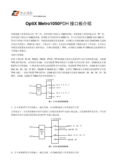
OptiX Metro1050PDH接口板介绍单板面板上的条码标记有“A”的,表明是接口阻抗为75Ω的单板;单板面板上的条码标记有“B”的,表明是接口阻抗为120Ω的单板。
E1/E3信号的码型为HDB3码,T1信号的码型为B8ZS或者AMI码,T3信号的接口码型为B3ZS码。
单板的前面板没有连接器,必须配合C12/C34S或者C34/C34S完成相应电信号的接入。
PDH接口板有一个指示灯(绿色)长亮表示单板配置了数据且处于工作状态,长灭表示单板没有配置业务或者处于保护状态。
当PL3板配置了TPS,必须配合C34S和TSB3板完成E3/T3信号的输入和输出。
电接口转接板C12与PL1D、PL1S、PM1D、PM1S、PF1D、PF1S板配合使用完成E1/T1电信号的转接功能,当配置TPS保护的时候,必须使用C12S。
在没有配置TPS的情况下C12S可以同C12 使用。
C34S板是3路E3/T3信号转接板,与PL3配合使用完成E3/T3信号电转接,设备配置TPS保护时,C34S板可以插在Slot 24,25,30,31槽位(Slot26和Slot32插入TSB3,必须有TSB3配合才能够完成E3/T3信号的TPS功能),设备不配置TPS保护时,C34S板作为信号转接板可以插在Slot 24,25,26,30,31,32槽位。
C12S、C34S和TSB3的参考原理图如下:µçÀµçÀÂDB78Á¬½ÓÆ÷slot 4£¬5£¬6£¬10£¬11slot 12slot 4£¬5£¬6£¬10£¬11slot 12¿ª¹Ø¿ØÖÆÄ£¿é图1.C12S板的原理框图1、以1路E1/T1信号的输入、输出为例,对C12S板的工作原理进行介绍正常状态下,开关控制模块中的开关指向工作板位的E1/T1电接口板总线;当有倒换事件发生时,开关控制模块中的开关指向保护板位的E1/T1电接口板总线。
OptiX Metro1050总线结构

OptiX Metro1050总线结构OptiX Metro1050设备最大提供20×20VC4(1260 1260 VC-12)的空分交叉能力,SLOT7和SLOT8(17和18逻辑板位)各占用4根总线;SLOT4/SLOT5/SLOT10/SLOT11各占2根总线;SLOT6/SLOT12上行有1根总线、下行有2根总线,这种设计主要目的是便于XCS 进行广播,完成PP/SNCP 保护功能。
各业务槽位到主备交叉槽位总线是完全对称的。
业务总线分配图如下 主交叉/时钟备交叉/时钟slot8slot7slot1slot2SPIUSPIUXCS slot9slot10slot11slot42×4X 38M 2×4X 38M 2×4X 38M 2×4X 38M slot7的slot8的slot54×4X 38M 2×4X 38M 2×4X 38M 4×4X 38M 2×4X 38M 2×4X 38M slot12slot62×4X 38M 2×4X 38M 1×4X 38M 1×4X 38M 2×4X 38M 2×4X 38M 1×4X 38M 1×4X 38M slot3FSCC光扣板光扣板4×4X 38M 4×4X 38M 4×4X 38M 4×4X 38M 4×4X 38M 4×4X 38M 2×4X 38M 2×4X 38M 2×4X 38M 2×4X 38M 2×4X 38M 2×4X 38M 2×4X 38M 2×4X 38M图1. 业务总线分布图OptiX Metro1050设备最大提供6路ECC 处理能力,SLOT4/SLOT5、/SLOT7/SLOT8、SLOT10/SLOT11各分配一路ECC 路由。
光传输网络组建与运行维护课件

32
4. 时钟单元板STG
光传输网络组建与运行维护课件
23
PD1板
与各单板之间的关系: a. 与D75/D12板:业务信号接口关系 b. 与交叉板:业务收发 c. 与时钟:通过交叉板接收时钟信息 d. 与主控:通过邮箱与之通信,上报告警与性 能事件,接收控制命令
e. 与电源:获取-48V电源要经本地电源模块转 化
光传输网络组建与运行维护课件
5
光传输网络组建与运行维护 ppt 课件
2. OptiX 155/622H(Metro 1000) 的IU板位
IU3 B
IU2 IU4 SCB
IU1 A
IU1:光/电接口板位,可以安插OI2S/OI2D/OI4/SB2等,但很少 安插电接口板; IU2,IU3:光/电接口板位,可以安插OI2S/OI2D/OI4/SB2; IU3:环境监控,可以安插EMU; IU4:电接口板位,可以安插PD2T/PM2/TDA/ET1/AIU等; SCB:系统控制板位; A:防尘网,电源滤波板,可以安插POI; B:风扇板位,FAN。
光传输网络组建与运行维护课件
24
拉手条指示灯
a. 绿:运行灯 100ms亮,100ms灭: 未开工状态 1s亮,1s灭;开工状态 2s亮,2s灭:脱机状态,与SCC板通信中断 b. 红:告警指示灯
常灭:无告警 危急:3次/ s 主要:2次/ s 次要:1次/ s 常亮:CPU自检未通过,硬件故障
SP1S与SP1D板由右至左依次引出4或8个2M接口。
应用:IU2、IU3板位。
参数:根据板上的跳线以决定2M接口的阻抗是75欧还是120欧。
光传输网络组建与运行维护课件
8
光传输网络组建与运行维护 ppt 课件
科远设备级驱动和自定义模块说明(新)

设备级驱动和自定义模块说明编制:黄轶青审核:曹瑞峰梅建华批准:刘国耀南京科远控制工程有限公司NANJING KEYUAN CONTROL ENGNEERING CO., LTD2003年11月目录1.不可调电动门(ACT15A3W:TVL_BT): (6)1.1模块原理 (6)1.2主要特性有: (6)1.3工作模式:(优先权由高到低) (8)1.4模块参数: (8)1.5不可调电动门在逻辑图中的表达方法如下例: (11)1.6如何组态参照组态演示文件. (11)2.点动门(ACT15A3W:TVL_DD): (13)2.1模块原理 (13)2.2主要特性有: (13)2.3工作模式:(优先权由高到低) (15)2.4模块参数: (15)2.5点动门在逻辑图中的表达方法如下例: (16)2.6如何组态参照组态演示文件. (16)3. 全开全关执行机构(ACT15A3W:TVL_AN): (17)3.1模块原理 (17)3.2模块参数: (17)3.3全开全关执行机构在逻辑图中的表达方法如下例: (18)3.4如何组态参照组态演示文件. (18)4.单位式设备(ACT15A3W:TVL_RS): (19)4.1模块功能 (19)4.2模块参数: (20)4.3单位式设备在逻辑图中的表达方法如下例: (20)4.4如何组态参照组态演示文件. (21)5.标准电机(ACT15A3W:TMT_ST): (21)5.1模块功能 (21)5.2主要特性有: (21)5.3工作模式:(优先权由高到低) (23)5.4模块参数: (23)5.5标准电机在逻辑图中的表达方法如下例: (24)5.6如何组态参照组态演示文件. (25)6.一带八设备模块(DIGACT:TCKGF8A): (26)6.1模块功能: (26)6.2主要特性有: (26)6.3模块参数: (26)6.4一带八设备模块在逻辑图中的表达方法 (27)6.5如何组态参照组态演示文件. (28)7.多功能软伺放(ACT15A3W:ANMMF): (29)7.1模块功能 (29)7.4模块参数: (31)7.5模块选型: (35)7.6如何组态参照组态演示文件. (35)8.四回路多输出T2500软伺放(ACTION:AMF): (36)8.1模块功能 (36)8.2主要特性有: (36)8.3工作模式: (37)8.4模块参数: (38)8.5模块选型: (39)8.6四回路多输出T2500软伺放在逻辑图中的表达方法 (40)8.7如何组态参照组态演示文件. (40)9.模拟量手操模块(ACTION:MANS): (42)9.1模块功能 (42)9.2主要特性有: (42)9.3工作模式: (43)9.4模块参数: (44)9.5模拟量手操站在逻辑图中的表达方法 (46)9.6如何组态参照组态演示文件. (46)10.二值优选模块(ACTION:OF2VOTE(FILENAME和ACTNAME)): (48)10.1模块功能 (48)10.2参数 (48)10.3二值优选模块在逻辑图中的表达方法如下例: (49)10.4如何组态参照组态演示文件. (49)11.自动冗余切换、故障集合及负荷率运算模块(ACTION:DIAG(FILENAME和ACTNAME)): 5011.1模块功能 (50)11.2模块参数 (50)11.3如何组态参照组态演示文件. (50)12.十一回路首出原因模块(ACT15A3W:ETSST(FILENAME和ACTNAME)): (51)12.1模块功能 (51)12.2模块参数 (51)12.3在逻辑图中的表达方法 (51)12.4如何组态参照组态演示文件. (51)13.串级回路抗积分饱和模块(ACTION:SERCO (FILENAME和ACTNAME)): (52)13.1块功能说明 (52)13.2参数 (52)13.3在逻辑图中的表达方法 (52)13.4如何组态参照组态演示文件. (52)14.两前馈协调模块(ACTION:NODISTB(FILENAME和ACTNAME)): (53)14.1模块原理该 (53)14.4如何组态参照组态演示文件. (53)15.过热蒸汽流量补偿(ACTION:MATH(FILENAME)FL_OVER(ACTNAME)): (54)15.1模块原理 (54)15.2参数 (54)15.3如何组态参照组态演示文件. (54)16.汽包水位补偿模块(ACTION:MATH(FILENAME)DLEL(ACTNAME)): (55)16.1模块原理 (55)16.2参数 (55)16.3如何组态参照组态演示文件. (55)17.积分处理模块(ACTION:INTGDW32(FILENAME和ACTNAME)): (56)17.1模块功能 (56)17.2参数 (56)17.3在逻辑图中的表达方法 (56)17.4如何组态参照组态演示文件. (56)18.一带八同操处理模块(ACTION:TCON(FILENAME和ACTNAME) (57)18.1模块功能 (57)18.2参数 (57)18.3在逻辑图中的表达方法 (58)18.4如何组态参照组态演示文件. (58)19.一带十二同操+一带四同操处理(ACT15A3W:TCON3W(FILENAME和ACTNAME)) (59)19.1模块功能 (59)19.2参数 (59)19.3在逻辑图中的表达方法 (60)19.4如何组态参照组态演示文件. (60)20.八路电量脉冲累积模块(ACTION:PLSTAT(FILENAME) STAT8(ACTNAME)) (61)20.1模块功能 (61)20.2参数 (61)20.3在逻辑图中的表达方法 (61)20.4如何组态参照组态演示文件. (61)21.机炉协调控制模块(ACT15A3W:LMCC(FILENAME和ACTNAME)): (62)21.1模块功能 (62)21.2模块参数 (62)21.3如何组态参照组态演示文件. (63)22.单元机组煤粉炉燃料控制模块 (64)22.1模块功能 (64)22.2模块参数 (64)22.3如何组态参照组态演示文件. (65)23.2参数 (66)23.3在逻辑图中的表达方法 (67)23.4如何组态参照组态演示文件. (67)24.MFT控制模块(DIGACT:ACT15A3W(FILENAME) MFT(ACTNAME)) (68)24.1模块功能 (68)24.2参数 (68)24.3在逻辑图中的表达方法 (69)24.4如何组态参照组态演示文件. (69)25.数字量三取二模块(ACTION:ACTION(FILENAME) LOGIC2_3(ACTNAME)) (70)25.1模块功能 (70)25.2参数 (70)25.3在逻辑图中的表达方法 (70)25.4如何组态参照组态演示文件. (70)26.数字量四取二模块(ACTION:ACTION(FILENAME) LOGIC2_4(ACTNAME)) (71)26.1模块功能 (71)26.2参数 (71)26.3在逻辑图中的表达方法 (71)26.4如何组态参照组态演示文件. (71)27.数字量四取三模块(ACTION:ACTION(FILENAME) LOGIC3_4(ACTNAME)) (72)27.1模块功能 (72)27.2参数 (72)27.3在逻辑图中的表达方法 (72)27.4如何组态参照组态演示文件. (72)28.数字量六取四模块(ACT15A3W:LOGMUL(FILENAME) LOGIC4_6(ACTNAME)) (73)28.1模块功能 (73)28.2参数 (73)28.3在逻辑图中的表达方法 (73)28.4如何组态参照组态演示文件. (73)29.数字量八取六模块(ACTION:LOGMUL(FILENAME) LOGIC6_8(ACTNAME)) (74)29.1模块功能 (74)29.2参数 (74)29.3在逻辑图中的表达方法 (74)29.4如何组态参照组态演示文件. (74)30.脉冲发生模块(DIGACT:PULSE(FILENAME) PULSE(ACTNAME)) (75)30.1模块功能 (75)30.2参数 (75)30.3在逻辑图中的表达方法 (75)30.4如何组态参照组态演示文件. (75)31.1.1开关型集成设备级模块的分类 (76)31.1.2.模拟量集成设备级模块的分类 (76)31.2MMI设备级连接 (78)31.2.1可调电动门(图标Dynamos名:NKTKGICO,面板Dynamos名:NKTVL_BT) (78)31.2.2点动式电动门(图标Dynamos名:NKTKGICO,面板Dynamos名:NKTVL_DD) (82)31.2.3全开全关执行机构(图标Dynamos名:NKTKGICO,面板Dynamos名:NKTVL_AN) (83)31.2.4电动机与泵(图标Dynamos名:NKTKGICO,面板Dynamos名:NKTMT_ST) (84)31.2.5断路器(图标Dynamos名:NKTKGICO,面板Dynamos名:NKTMT_DL) (85)31.2.6单位式设备(图标Dynamos名:NKTKGICO,面板Dynamos名:NKTVL_RS) (86)31.2.7双线圈电磁阀(图标Dynamos名:NKTKGICO,面板Dynamos名:NKTVL_RS) (87)31.2.8调整门1:单PID调节,并且现场设备的接口为AO (88)31.2.9调整门2:单PID调节,并且现场设备的接口为PO (90)31.2.10调整门3:串级PID调节,并且与现场设备的接口为AO (91)31.2.11调整门4:无PID调节,纯手动操作设备,与现场设备的接口为AO (91)32.附录 (93)1.不可调电动门(ACT15A3W:TVL_BT):1.1模块原理Fig. 1.1 不可调电动门模块的逻辑图请参看图1.1,该设备模块用于驱动一个不可调整型电动门,接收从现场设备来的“已开和已关信号”,根据逻辑判断发出DO信号控制现场电动门全开或全关。
Zebra 105SL 条码打印机分解图

Part Number
G32011M G32101M
Kit Quantity
1 1
3
105SL Parts Catalog
Drive System Components
Item Number
1 1 2 3 4 5 6 7
Description
Kit DC Stepper Motor w/Pulley 203 DPI Kit DC Stepper Motor w/Pulley 300 DPI Main Drive Belt Media Rewind Belt Kit Platen Pulley Kit Peel Roller Pulley Kit Pulley for Media Take Up & Ribbon Take Up Rewind Idler Pulley Idler Pulley Shaft
Part Number
G22613M G38226M G46665M G46609-4M G32028M G46352M
Kit Quantity
1 1 1 1 1 1
5
105SL Parts Catalog
Electronics
Item Number
Description
Kit Main Logic Board 105SL 4MB (Use with printers that have configuration 10500-2XXX-XXXX and 10500-3XXX-XXXX) Kit Main Logic Board 105SL 64MB (Use with printers that have configuration 10500-2XXX-XXXX and 10500-3XXX-XXXX) Kit PCMCIA Board Assy (Use with printers that have configuration 10500-2XXX-XXXX and 10500-3XXX-XXXX) Kit AC/DC Power Supply (Use with printers that have configuration 10500-2XXX-XXXX and 10500-3XXX-XXXX) IPv4 Internal Print Server 10/100 IPv4 IPv4 Internal Print Server II 10Base-T IPv4 Kit Wireless Plus Board. In order to achieve wireless function, a separate radio card must be purchased (not included). IPv4 External Print Server 10/100 IPv4 Kit IBM Twinax Upgrade (includes Twinax Cable) IBM Twinax Cable Kit IBM Coax Upgrade (includes Coax Cable) Coax Ext IBM Cable IPv6 Internal Print Server IPv6 IPv6 External Print Server IPv6
OptiX OSN1500$2500$3500电源保护专题
OSN1500 由 AUX 板提供 3.3V 备份电源来实现,备份电源输出最大功率 80W , 对所有单板都提供保护。
都是软件检测触发倒换。
课程内容
OptiX OSN 2500/3500设备- 48V电源与1+1保护系统
OptiX OSN 2500/3500单板3.3V电源1:N保护系统
电源系统供电介绍
OSN2500
单子架满配置功耗350W,保险容量一般选择15A。 SAP板检测电源,若对 -60V 电源检测,可以拆掉 SAP 板上的 J9、
J10跳线帽实现
考虑子架及机柜扩容,3500/2500用户列头柜侧电源保险建议选 择32A或40A
OSN 1500
单子架满配置功耗280W,保险容量一般选择10A AUX板监控电源电压,该板没有指示灯,可用网管、命令行查询电
关键电源模块备份及供电方式说明
OSN 3500 SCC板的PWRA/B指示灯
绿色 PIU不在位 红色 PIU在位无电源接入或防雷单元失效等硬件故障
OSN 2500 SAP的STAT指示灯
绿色 PIU不在位时(或PIU在位,且只有一路电源接入) 红色 PIU在位无电源接入或雷单元失效等硬件故障
TA105403 OptiX OSN 1500/2500/3500 电源系统
课程目标
了解OptiX OSN 1500/2500/3500设备电源系统
了解OptiX OSN 1500/2500/3500设备各类电源保
护的机理与功能
课程内容
OptiX OSN 1500/2500/3500设备- 48V电源与1+1保护系统
BQ51050B 原理参考图

IMPORTANT NOTICE FOR TI REFERENCE DESIGNSTexas Instruments Incorporated("TI")reference designs are solely intended to assist designers(“Buyers”)who are developing systems that incorporate TI semiconductor products(also referred to herein as“components”).Buyer understands and agrees that Buyer remains responsible for using its independent analysis,evaluation and judgment in designing Buyer’s systems and products.TI reference designs have been created using standard laboratory conditions and engineering practices.TI has not conducted any testing other than that specifically described in the published documentation for a particular reference design.TI may make corrections,enhancements,improvements and other changes to its reference designs.Buyers are authorized to use TI reference designs with the TI component(s)identified in each particular reference design and to modify the reference design in the development of their end products.HOWEVER,NO OTHER LICENSE,EXPRESS OR IMPLIED,BY ESTOPPEL OR OTHERWISE TO ANY OTHER TI INTELLECTUAL PROPERTY RIGHT,AND NO LICENSE TO ANY THIRD PARTY TECHNOLOGY OR INTELLECTUAL PROPERTY RIGHT,IS GRANTED HEREIN,including but not limited to any patent right,copyright,mask work right, or other intellectual property right relating to any combination,machine,or process in which TI components or services are used. Information published by TI regarding third-party products or services does not constitute a license to use such products or services,or a warranty or endorsement e of such information may require a license from a third party under the patents or other intellectual property of the third party,or a license from TI under the patents or other intellectual property of TI.TI REFERENCE DESIGNS ARE PROVIDED"AS IS".TI MAKES NO WARRANTIES OR REPRESENTATIONS WITH REGARD TO THE REFERENCE DESIGNS OR USE OF THE REFERENCE DESIGNS,EXPRESS,IMPLIED OR STATUTORY,INCLUDING ACCURACY OR COMPLETENESS.TI DISCLAIMS ANY WARRANTY OF TITLE AND ANY IMPLIED WARRANTIES OF MERCHANTABILITY,FITNESS FOR A PARTICULAR PURPOSE,QUIET ENJOYMENT,QUIET POSSESSION,AND NON-INFRINGEMENT OF ANY THIRD PARTY INTELLECTUAL PROPERTY RIGHTS WITH REGARD TO TI REFERENCE DESIGNS OR USE THEREOF.TI SHALL NOT BE LIABLE FOR AND SHALL NOT DEFEND OR INDEMNIFY BUYERS AGAINST ANY THIRD PARTY INFRINGEMENT CLAIM THAT RELATES TO OR IS BASED ON A COMBINATION OF COMPONENTS PROVIDED IN A TI REFERENCE DESIGN.IN NO EVENT SHALL TI BE LIABLE FOR ANY ACTUAL,SPECIAL,INCIDENTAL,CONSEQUENTIAL OR INDIRECT DAMAGES,HOWEVER CAUSED,ON ANY THEORY OF LIABILITY AND WHETHER OR NOT TI HAS BEEN ADVISED OF THE POSSIBILITY OF SUCH DAMAGES,ARISING IN ANY WAY OUT OF TI REFERENCE DESIGNS OR BUYER’S USE OF TI REFERENCE DESIGNS.TI reserves the right to make corrections,enhancements,improvements and other changes to its semiconductor products and services per JESD46,latest issue,and to discontinue any product or service per JESD48,latest issue.Buyers should obtain the latest relevant information before placing orders and should verify that such information is current and complete.All semiconductor products are sold subject to TI’s terms and conditions of sale supplied at the time of order acknowledgment.TI warrants performance of its components to the specifications applicable at the time of sale,in accordance with the warranty in TI’s terms and conditions of sale of semiconductor products.Testing and other quality control techniques for TI components are used to the extent TI deems necessary to support this warranty.Except where mandated by applicable law,testing of all parameters of each component is not necessarily performed.TI assumes no liability for applications assistance or the design of Buyers’products.Buyers are responsible for their products and applications using TI components.To minimize the risks associated with Buyers’products and applications,Buyers should provide adequate design and operating safeguards.Reproduction of significant portions of TI information in TI data books,data sheets or reference designs is permissible only if reproduction is without alteration and is accompanied by all associated warranties,conditions,limitations,and notices.TI is not responsible or liable for such altered rmation of third parties may be subject to additional restrictions.Buyer acknowledges and agrees that it is solely responsible for compliance with all legal,regulatory and safety-related requirements concerning its products,and any use of TI components in its applications,notwithstanding any applications-related information or support that may be provided by TI.Buyer represents and agrees that it has all the necessary expertise to create and implement safeguards that anticipate dangerous failures,monitor failures and their consequences,lessen the likelihood of dangerous failures and take appropriate remedial actions.Buyer will fully indemnify TI and its representatives against any damages arising out of the use of any TI components in Buyer’s safety-critical applications.In some cases,TI components may be promoted specifically to facilitate safety-related applications.With such components,TI’s goal is to help enable customers to design and create their own end-product solutions that meet applicable functional safety standards and requirements.Nonetheless,such components are subject to these terms.No TI components are authorized for use in FDA Class III(or similar life-critical medical equipment)unless authorized officers of the parties have executed an agreement specifically governing such use.Only those TI components that TI has specifically designated as military grade or“enhanced plastic”are designed and intended for use in military/aerospace applications or environments.Buyer acknowledges and agrees that any military or aerospace use of TI components that have not been so designated is solely at Buyer's risk,and Buyer is solely responsible for compliance with all legal and regulatory requirements in connection with such use.TI has specifically designated certain components as meeting ISO/TS16949requirements,mainly for automotive use.In any case of use of non-designated products,TI will not be responsible for any failure to meet ISO/TS16949.Mailing Address:Texas Instruments,Post Office Box655303,Dallas,Texas75265Copyright©2015,Texas Instruments Incorporated。
多普达710拆机解剖图
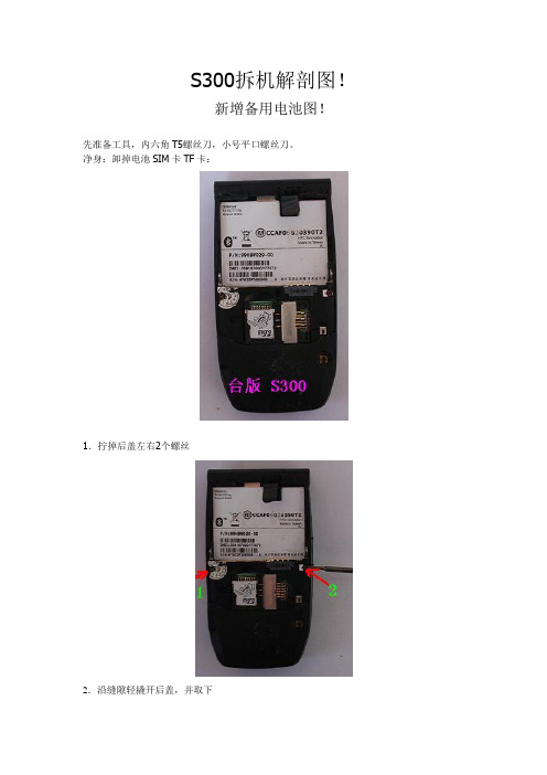
S300拆机解剖图!
新增备用电池图!
先准备工具,内六角T5螺丝刀,小号平口螺丝刀。
净身:卸掉电池SIM卡TF卡:
1.拧掉后盖左右2个螺丝
2.沿缝隙轻撬开后盖,并取下
先开上面,再小平口螺丝刀撬开左边,插进张卡片,撬开右边,到下面有四个大的卡扣就要用力了。
速度要慢。
3.十字螺丝刀拧下主板左右固定螺丝
4.拔掉连接主板键盘的排线
5.。
轻撬商标铁壳,双面胶固定的,很容易揭开。
6,拔掉主板排线
取下主板
沿此孔斜向上轻捅
根据捅开的缝隙揭开键盘
键盘也是双面胶固定的
一字螺丝刀沿上盖侧键缝隙轻撬打开上盖
T5螺丝刀拧开左右2个固定螺丝
镊子拔掉排线
撬开外屏功能键外盖,拔掉喇叭线
取下外屏盖
十字螺丝刀取下左右2个外屏固定螺丝
取下外屏和摄像头连接排线
轻撬铁壳
21.JPG取下内外屏总成和摄像头模块
十字螺丝刀拧下转轴螺丝
取下手机挂绳孔,我的已经断了,用木螺丝拧进去再拔出来
右侧转轴销子有卡扣,
轻轻按下推出即可
立起手机手机挂绳那侧有转轴弹簧
用螺丝刀伸进去下压即可取下
沿缝隙取下连带
排线和主板
光感键盘
摄像头组件
画圈处为备用电池,更换时注意焊接方式及电池型号。
OPT(C805)-光纤通信板
目录C805OPT光纤通信板 (1)功能及原理 (1)面板及指示灯说明 (2)开关及跳线说明 (3)技术指标 (4)外部配线 (4)C805OPT 光纤通信板功能及原理OPT 板是光纤接口板,它和FBI 板一起,实现了SM 和AM/CM 之间的通信连接,其可靠性和稳定性对于模块间的通信乃至交换机的稳定都具有十分重要的意义。
C805OPT 板是C803OPT 板的优化版本,它提高了器件的集成度,解决了相关器件的停产问题,采用了性能更加稳定的器件,增加了CPU 和邮箱,增加了后台维护信息,增强了对单板的维护功能。
OPT 光纤通信板的主要功能有:(1) 与FBC 板一起,在SM 和AM/CM 之间建立话路信息通道; (2) 在SM 和AM/CM 之间建立通信数据通道; (3) 为SM 中的网板提供时钟信号;(4) 具有码流同步,以及OPT 本板自环的功能。
OPT 板原理框图如图1所示。
NET 板MC2MC2NET 板板板图1 OPT 板原理框图OPT 是光纤通信板,它将FBC 板经光纤传来的光信号先由光器件进行光电转换,电信号经放大之后,提取出时钟并恢复信码,然后分接出HW 信号送给网板BNET ,HDLC 链路信号送给MC2板,同时OPT 板还判断光路中是否产生失步、误码、对告等信号;另一方面,OPT 板将网板BNET 送来的HW 信号、MC2板传来的HDLC 链路信号复接成高速码流,经电平调整后送给光器件进行电光转换,然后通过光纤发送出去。
面板及指示灯说明图2为C805OPT单板面板图。
表1描述了C805OPT单板面板上各指示灯的具体含义。
图2C805OPT板面板图表1C805OPT板指示灯说明灯名颜色含义说明正常状态RUN 红运行指示灯1秒亮1秒灭,与主机通讯时快闪几下1秒亮1秒灭ACT 绿主备用指示灯主用时亮,备用时灭亮/灭RNL 绿有/无光信号指示灯无光时亮,有光时灭灭LFA 绿光路失步指示灯失步时亮,同步时灭灭BER 绿误码指示灯有误码时亮,无误码时灭灭灯名颜色含义说明正常状态RMT 绿对端故障指示灯故障时亮,正常时灭灭LOF 绿时钟检测指示灯无时钟时亮,有时钟时灭灭LOP 绿自环指示灯自环时亮,正常时灭灭LFAP 绿链路失步指示灯失步时亮,同步时灭灭DONE 绿 FPGA加载指示灯加载时亮,正常时灭灭开关及跳线说明图3为C805OPT单板布局示意图,表2为C805OPT板跳线含义,单板内部无开关。
IPG高功率光纤激光器结构图ppt课件

IPG高功率光纤
+
+
+
+ = xxx kW 激光器模块组
UART
InterBus
主
控
Eithernet
制
器
43 kW
MCU P=500W MCU P=500W
MCU P=500W MCU P=500W 电源
合束器
光闸
Length 200 m 10 kW 10 kW
4
IPG高功率光纤激光器配备外部光闸进行激光加工
IPG高功率光纤激光器结构图
1
IPG光纤激光器泵浦源—单芯结半导体模块
- 超高的功率 - 超高的亮度 - 极高的效率 - 无冷却运行
2
IPG光纤激光器模块组
+
LDM#
LDM#
LDM#
有源光纤
+
LDM#
LDM#
LDM#
LDM#
LDM#LDM#-来自光纤模组全光纤激光模块组
LDM#
LDM#
LDM#
-
体积小巧,高度集成的全光纤设计 并联单芯结二极管激光模块组合 侧面泵浦 坚固的机械结构,耐冲击稳定性及强 超高的温度稳定性
Feeding Fiber Length up to 200m
Process Fiber Length up to 200m
• 远距离的光传输 • 安装简易 • 节省费用 • 操作安全
5
IPG高功率光纤激光器内部水循环系统
6
此课件下载可自行编辑修改,供参考! 感谢您的支持,我们努力做得更好!
7
光耦9505原理

光耦9505原理光耦(Optocoupler)是一种能够实现光电隔离的器件,常用于电气设备中的信号隔离、电气隔离和电气耦合等应用。
光耦的原理是利用光电效应,将输入端的电信号转换为光信号,再通过光电转换将光信号转换为输出端的电信号,从而实现输入和输出的电气隔离。
光耦的常见类型之一是光耦9505,它具有高速、高灵敏度、高耐压等特点,在工业领域中得到广泛应用。
光耦9505由发光二极管(LED)和光敏三极管(Phototransistor)组成。
当输入端施加电压时,LED会发出光信号,光信号经过隔离区域后被光敏三极管接收,产生电流,从而在输出端产生电压。
光耦9505的工作原理基于半导体物理学的原理。
当LED输入端加上正向电压后,LED内部的载流子被激发,产生光辐射。
这些光子穿过隔离区域,照射到光敏三极管上,光敏三极管的电流增大。
由于光敏三极管是一个受控的电流源,所以当输入端的电压变化时,输出端的电流也会相应变化。
光耦9505的工作过程可以分为两个阶段:输入阶段和输出阶段。
在输入阶段,当输入端施加电压时,LED发出光信号,光信号经过隔离区域后照射到光敏三极管上。
在输出阶段,光敏三极管接收到光信号后,产生电流,从而在输出端产生电压。
这种输入和输出的电气隔离使得光耦能够实现信号隔离和电气隔离的功能。
光耦9505的特点之一是高速性能。
由于光的传播速度非常快,因此光耦能够实现高速的信号传输。
这使得光耦在需要高速响应的应用中具有优势,例如在通信设备中实现信号隔离和电气隔离。
光耦9505的另一个特点是高灵敏度。
由于光敏三极管接收到的光信号能够转化为电流信号,因此光耦具有很高的灵敏度。
这使得光耦能够在低功率输入的情况下实现较高的输出电流,提高了系统的效率和稳定性。
光耦9505还具有高耐压的特点。
光耦的输入端和输出端之间存在隔离区域,能够承受一定的电压。
这种高耐压特性使得光耦能够在高压环境下正常工作,提高了系统的可靠性和安全性。
骨架式光缆

G.655
≤0.25 dB/km @1550 nm
≤1520 nm ≤1480 nm 9.6±0.5 µm @ 1550 nm 125.0±1.0µm ≤1.0% ≤0.8 µm ≥100 kpsi
光缆机械及环境特性
最小弯曲半径:10×外径(静态),20×外径(动态) 最大拉伸强度:1500N(短期),600N(长期) 允许压扁力:1000N/10cm(短期),300N/10cm(长期) 工作温度范围: -40 ℃ ~+70 ℃
光缆结构示意图光缆结构示意图8芯带结构芯带结构光纤规格光纤规格g652dg655衰减038dbkm1310nm025dbkm1550nm025dbkm1550nm零色散波长1302nm1322nm1520nm截止波长cc1260nm1480nm模场直径9204?m1310nm9605?m1550nm包层直径125010?m125010?m包层不圆度1010芯包同心度误差08?m08?m筛选张力100kpsi100kpsi光缆机械及环境特性光缆机械及环境特性最小弯曲半径
光缆结构示意图(8芯带结构)
光纤规格
衰减
零色散波长 截止波长 (λcc) 模场直径 包层直径 包层不圆度 芯/包同心度误差 筛选张力
G.652D ≤0.38 dB/km @1310 nm ≤0.25 dB/km @1550 nm
1302 nm – 1322 nm ≤1260 nm 9.2±0.4 µm @ 1310 nm 125.0±1.0 µm ≤1.0% ≤0.8 µm ≥100 kpsi
骨架式光缆
产品规格书
特性及应用 罗森伯格骨架式光缆具有优越的光学性能,符合IEC-60793和IEC-60794标准。因其良好的抗压能力和高密度大芯数带纤结构,尤其适 合应用于光纤分配网络,提高了熔接效率,节省安装和维护成本。罗森伯格骨架式光缆可达到最大芯数1000芯结构,适用于架空和管 道安装环境。光纤带分为4芯带(适用于300芯以下)和8芯带(适用于300芯以上)两种结构。
