SCv2000InstallationGuide(update)
Installation Instructions说明书

Installation Instructions Montageanleitung Montážní návodMonteringsvejledning Paigaldusjuhend AsennusohjeNotice de montageSzerelési útmutatóUputstvo za montažu Montagehandleiding Instructiuni de montajEN DE CZ DKEE FI FR HU HR NLROIstuzioni di montaggio Montavimo Instrukcijos Instalacijas instrukcija MonteringsanvisningInstrukcja montażu InstallationsanvisningИнструкция по монтажуInstrukcija za instalaciju Montážny návodNavodilo za montažo 安装说明书IT LT LV NO PL SE RU SRB SK SLO CN—1——2—L1.Installation and commissioning may only be carried out by authorized specialistsand wired in cordance with the latest IEE electrical regulations or the national standards.2.Mains power must be switched off before carrying out installation.3.The manufacturer, shall not be liable for any damage resulting from inappropriate modifications to the luminaire or faulty installation.4. Indoor use only.5. Caution, risk of electric shock.The control gear provides basic insulation between the LV supply and the control circuit.96630223 ANNA Suspension KitANNA LED PANELZumtobel LIGHTING GmbH Schweizer Strasse 30 A-6851 Dornbirn AUSTRIA URL:Safety Wire Installation ManualSuspension Kit User Manual96631383 ANNA 1200x300 Suspension KitSuspension Kit User Manual96630066ANNA LED Q5963750 840√√√96630067ANNA LED Q6223750 840622x622x8.5622x622x8.596630068ANNA LED Q5963750 840 E396630069ANNA LED Q5963400 83096630070ANNA LED Q6223400 83096631380ANNA LED 1200x300 4400 8401196x296x8.5Product DescriptionWattage PF InputSAP Code Dimension LxWxH(mm)Safety wireOperating temperature +5~+25°C-20~40°C -20~40°C 596x596x8.5AC220-240V50/60Hz 0.934W AC220-240V50/60Hz0.934W-20~40°C -20~40°C -20~40°C 596x596x8.5AC220-240V 50/60Hz0.934W 596x596x8.5AC220-240V 50/60Hz AC220-240V 50/60Hz AC220-240V 50/60Hz0.90.90.90.934W 34W40W L150096631381ANNA LED 1200x300 4000 830L1500 96630223ANNA Suspension Kit96631383ANNA 1200x300 Suspension Kit√√√622x622x8.5622x622x8.51196x296x8.5+5~+35°C-20~40°C -20~40°C -20~40°C AC220-240V50/60Hz AC220-240V50/60Hz0.934W-20~40°C -20~40°C596x596x8.5AC220-240V 50/60Hz0.934W596x596x8.5596x596x8.5AC220-240V 50/60Hz AC220-240V 50/60Hz AC220-240V 50/60Hz0.90.934W 34W 0.934W40W 96631113ANNA LED Q5963750 840 HFIX 96631114ANNA LED Q6223750 840 HFIX 96631115ANNA LED Q5963750 840 HFIX E3 96631116ANNA LED Q5963400 830 HFIX 96631117ANNA LED Q6223400 830 HFIX—3——4—Zumtobel LIGHTING GmbHSchweizer Strasse 30A-6851 Dornbirn AUSTRIA URL:IK02IP 20—44BO-LLHT04A002-01。
Dell Storage Center SCv2000 和 SCv2020 存储系统 用户手册

目录
关于本指南.................................................................................................................. 5
1 关于 SCv2000/SCv2020 存储系统.......................................................................7
SCv2000/SCv2020 存储系统监测和诊断程序....................................................................................... 7 SCv2000/SCv2020 存储系统硬件......................................................................................................... 7
修订历史记录.......................................................................................................................................... 5 读者对象................................................................................................................... 5 相关出版物............................................................................................................................................. 5
V200S VERIS Verabar (单杆)安装和维护手册说明书

V200S VERIS Verabar® (Single Rod) Installation and Maintenance Manual169-EN Please read and savethese instructionsContentsGeneral Safety Information (3)Product Information (3)Section 1: Scope (3)Section 2: Receiving and InspectingSection 3: Safety Precautions (3)Section 4: Installation Preparations ......................................................3-5Location (3)Orientation (4)Horizontal Piping (4)Vertical Piping (5)DP Transmitter/Local Indicator Location (5)Installation Drawings and Bill of Materials (5)Piping Support (5)Section 5: Installation Procedure .........................................................6-9Assemble the Verabar® (6)Insert Instrument Vales or Manifold (6)Valves (6)Manifold (6)Retract Sensor and Tighten Packing (7)Weld Thread-o-let to Pipe (7)Install Close Nipple & Access Valve (7)Drill Hole in Pipe (7)Mount Sensor Assembly to Access Valve (8)Vent Access Valve to Verify No Leaks are Present (8)Grease Drive Rod (8)Insert Verabar® Sensor Assembly (8)Orientation of Flow Arrow (9)Section 6: Proper Installation (10)Section 7: Periodic Maintenance (10)Limited Warranty and Remedy (11)2Designs, materials, weights and performance ratings are approximate and subject to change without notice.Visit armstrong for up-to-date information.3Designs, materials, weights and performance ratings are approximate and subject to change without notice.Visit armstrong for up-to-date information.Section 1 ScopeThese instructions provide a description of procedures for installing the V200S (Single Rod) Verabar ® flow sensor. Procedures are given for all industrial flow measurement applications including liquid, steam and gas for both horizontal and vertical piping configurations.Section 2 Receiving InspectionThe following tasks should be performed as part of the receiving inspection procedure:• Check items received against the packing list.• Check sensor nameplate for proper model number, serial number and tag number.• Verify the actual pipe diameter matches the ID stated on the sensor nameplate.• Check the bullet shaped sensor tube for any signs of damage. Damage to the sensor tube may result in erroneous flow readings.• Check the round cover tube for any damage, especially axial gouges or scratches. Damage to the cover tube may prevent the packing from sealing properly.Section 3 Safety PrecautionsThe following process should be conducted prior to installing the Verabar ® flow sensor:• Check the maximum operating conditions on the flow sensor nameplate. If any pressure, temperature or flow limits will be exceeded, contact the factory before proceeding.Section 4 Installation Preparations4.1 LocationFor the most accurate flow measurement, a minimum straight run of pipe is required. Table 1 shows the minimum straight run requirements. If longer straight runs are available, position the Verabar ® such that the ratio of upstream straight run to downstream straight run is approximately 4 to 1. If straight run lengths are less than the values stated in Table 1, contact Armstrong’s VERIS Flow Measurement Group directly. Straightening vanes should be positioned such that the end closest to the Verabar ® is half way between the Verabar ® and the closest upstream configuration. For elbow installations, mount the Verabar ® in the same planeas the closest upstream elbow.General Safety InformationProduct InformationInstructions and procedures listed in this manual may require special precautions to ensure the safety of the individuals performing the operations. Review the entire manual, taking note of safety messages prior to performing any operations listed in the manual.The VERIS Verabar ® averaging pitot flow sensor provides unsurpassed accuracy and reliability. With its solid, one-piece construction and bullet shape the VERIS Verabar ® makes flow measurement reliable and precise.The unique sensor shape reduces drag and flow induced vibration. The location of the low-pressure ports eliminates the potential for clogging and improves signal stability.The V200S model can be inserted and removed from service under pressure. It features a single drive rod and threaded mounting components.4Designs, materials, weights and performance ratings are approximate and subject to change without notice.Visit armstrong for up-to-date information.Table 1. Straight Run Requirements4.2 OrientationVerify the proper sensor orientation by checking for an “-H” (horizontal piping) or a “-V” (vertical piping) in the model number on the Verabar ® name plate. Verify that the flow arrow stamped on the instrument head is pointing downstream in the direction of flow.4.2.1 Horizontal PipingFor air or gas installations, mount the Verabar ® in the upper 160° of the pipe to allow any condensate to draininto the pipe (Figure 1). For liquid or steam installations, mount the Verabar ® in the lower 160° of the pipe. Thisallows any entrained air to bleed back into the pipe for liquid applications and allows condensate to collect in theinstrument piping for steam applications.5Designs, materials, weights and performance ratings are approximate and subject to change without notice.Visit armstrong for up-to-date information.Figure 1. Verabar ® Orientation in Horizontal Pipe4.2.2 Vertical PipingThe Verabar ® may be mounted in any location around the circumference of the pipe for vertical piping applications.4.3 DP Transmitter/Local Indicator LocationWhen choosing a Verabar ® location, consider the DP transmitter/local indicator location:• The transmitter must be mounted below the Verabar ® for liquid and steam applications.• The transmitter must be mounted above the Verabar ® for air and gas applications.4.4 Installation Drawings and Bill of MaterialsAdditional information is available in the Installation Drawings and Bill of Materials VB-7061. (Contact factory foraccess information). It contains standard and alternate transmitter locations and a complete bill of materials based on the fluid type and sensor orientation on the pipe.4.5 Piping SupportFor sensors that extend more than 36” (915mm) beyond the pipe wall or for sensors mounted in thin-walled pipes, external support of the Verabar ® is recommended. This will reduce stresses on the pipe wall.6Designs, materials, weights and performance ratings are approximate and subject to change without notice.Visit armstrong for up-to-date information.Figure 3. Access NippleSection 5 Installation Procedure5.1 Assemble The Verabar ®Your Verabar ® is shipped loosely assembled and is not properly tightened for proper pressure retention. Follow all assembly steps to ensure a safe installation (see Figure 2).5.2 Insert Instrument Vales or Manifold5.2.1 Valves• If the Verabar ® does not have a valve head, install instrument valves using proper thread sealant. Be sureinstrument shut-off valves are installed and shut prior to re-pressurizing the pipe.5.2.2 Manifold• If the Verabar ® has a direct or integral manifold, be sure the high and low pressure block valves are shutoff prior to re-pressurizing the pipe.Figure 2. Verabar ® Model V200S (Single Rod)Instrument HeadHot Tap Drilling Mechanism (Not Supplied)Thread-o-let Close Nipple Sensor Plate Cover TubeSensorPacking Bolts Packing Gland Access Nipple Stop Nut Drive RodJam NutDrive NutBushingBushingPacking GlandNippleAccess NippleCover Tube7Designs, materials, weights and performance ratings are approximate and subject to change without notice.Visit armstrong for up-to-date information.5.3 Retract Sensor and Tighten Packing• Retract the Verabar ® such that the tip of the sensor is flush with the end of the access nipple (Figure 3). Tighten the three packing bolts on the packing gland.5.4 Weld Thread-o-let to Pipe• Mark the location where the Verabar ® is to be mounted. Position the Thread-o-let over the center of the mark. Using the appropriate weld gap (1/16” [1.5mm] typical), tack weld the Thread-o-let into position. Protect threads on the Thread-o-let, then finish welding the Thread-o-let to the pipe per applicable codes.5.5 Install Close Nipple & Access Valve• Using the appropriate pipe thread sealant, install close nipple and access valve. Orient the valve (Figure 4) such that for horizontal pipes the valve handle is in-line (perpendicular for vertical pipes) with the centerline of the pipe. Be sure the valve handle does not hit the pipe during opening and closing of the valve. Verify that the close nipple and access valve are properly tightened, because beyond this point, they will not be serviceable without depressurizing the line.Figure 4. Weld Gap5.6 Drill Hole in Pipe• With the access valve in the full open position, install an appropriate Hot Tap Drilling Machine (Figure 5) and drill a hole in the pipe (hole sizes per chart below). Follow the instructions given by the Hot Tap Drilling Machine.• After the hole is completely drilled, retract the Hot Tap Drilling Machine. Shut off the access valve prior to removal of theHot Tap Drilling Machine.Access ValveClose NippleThread-o-let Gap (1/16” [1.55mm] Typical)Tack weldProtect threads Complete weldFigure 5. Hot Tap Drilling Machines5.7 Mount Sensor Assembly to Access ValveApply appropriate thread sealant to the access nipple and thread the access nipple into the access valve. Orient thesensor such that the arrow labeled “FLOW” on the instrument head is in the direction of the flow in the pipe within 3°(orientation per Figure 6).5.8 Vent Access Valve to Verify No Leaks are PresentWith the instrument valves shut, slowly crack open the access valve and verify that there are no process fluid leaks. Ifleaks are present, shut off the access valve and tighten the leaky joint.5.9 Grease Drive Rod• High temperature grease has been applied to the threaded rod at the factory. Verify the threaded rod is adequatelygreased prior to inserting the sensor. If necessary, smear grease on the threaded drive rod. A high temperaturegrease should be used on all steam applications and for temperatures above 200°F.• Grease should be applied prior to subsequent insertions and retractions.5.10 Insert Verabar® Sensor AssemblyWarning: The flow rate must be decreased to the maximum insertion/withdrawn DP/flow limit stated on theVerabar® nameplate.• The Verabar® should be oriented such that the arrow on the head is pointing in the direction of the flow.• Completely open the access valve. Then, using the drive nut, insert the sensor.• The tip of the sensor should completely bottom on the opposite end of the pipe. Continue to insert the sensor untilfirm resistance is met. This will occur when the sensor plate is approximately 2” [51mm] from the top of the packinggland.• Thread the jam nut toward the threaded bushing. The jam nut should press tightly against the threaded bushing. Thiswill lock the drive rod in place and maintain the sensor position in the pipe.8Designs, materials, weights and performance ratings are approximate and subject to change without notice.Visit armstrong for up-to-date information.9Designs, materials, weights and performance ratings are approximate and subject to change without notice.Visit armstrong for up-to-date information.Figure 6. Orientation of Flow ArrowVertical Pipe OrientationsHorizontal Pipe OrientationsDirection of Flowof FlowDirection of Flow10Designs, materials, weights and performance ratings are approximate and subject to change without notice.Visit armstrong for up-to-date information.Section 6 Periodic MaintenanceThe assembly should be periodically checked. Verify that no leaks are present. The jam nut and packing bolts shouldbe tight.Section 7 Sensor Removal Procedure• Shut off instrument valves• Reduce flow rate below the maximum insertion/withdrawn DP/flow limit stated on the Verabar ® nameplate.• Loosen jam nut.• Using the drive nut, retract the sensor until the stop nut and jam nut are pressing against the threaded bushing. • Completely shut off the access valve. Slowly crack open one of the Verabar ® instrument valves and bleed off anyremaining pressure contained in the access nipple. The sensor assembly can now be removed.Verabar ® is now properly installed (Figure 7)Instrument Head Sensor PlateAccess ValvePacking BoltsPacking GlandAccess NippleThread-o-letClose NippleStop NutThreaded Drive RodJam Nut Drive NutThreaded BushingSensor Bushing Cover TubeSensorFigure 7. Installed V200S (Single Rod)11Designs, materials, weights and performance ratings are approximate and subject to change without notice.Visit armstrong for up-to-date information.VERIS, Inc. (“VERIS”) warrants to the original user of those products supplied by it and used in the service and in the manner for which they are intended shall be free from defects in material and workmanship for a period of five (5) years from the date of installation, but not longer than 63 months from the date of shipment from the VERIS factory, unless a Special Warranty Period applies, as noted below. This warranty does not extend to any product that has been subject to misuse, neglect or alteration after shipment from the VERIS factory. Except as may be expressly provided in a written agreement between VERIS and the user, which is signed by both parties, VERIS DOES NOT MAKE ANY OTHER REPRESENTATIONS OR WARRANTIES, EXPRESS OR IMPLIED, INCLUDING, BUT NOT LIMITED TO, ANY IMPLIED WARRANTY OF MERCHANTABILITY OR ANY IMPLIED WARRANTY OF FITNESS FOR A PARTICULAR PURPOSE. The sole and exclusive remedy with respect to the above limited warranty or with respect to any other claim relating to the products or to defects or any condition or use of the products supplied by VERIS, however caused, and whether such claim is based upon warranty, contract, negligence, strict liability, or any other basis or theory, is limited to VERIS’ repair or replacement of the part or product, or, at VERIS’ option, to repayment of the purchase price. In addition to replacing any part of parts found to VERIS’ satisfaction to be defective, VERIS will pay the cost of shipment of both the defective part to the VERIS plant and the replacement part to the original user. As a condition of enforcing any rights or remedies relating to VERIS products, notice of any warranty or other claim relating to the products must be given in writing to VERIS: (i) within 30 days of last day of the applicable warranty period, or (ii) within 30 days of the date of the manifestation of the condition or occurrence giving rise to the claim, whichever is earlier. IN NO EVENT SHALL VERIS BE LIABLE FOR SPECIAL, DIRECT, INDIRECT, INCIDENTAL OR CONSEQUENTIAL DAMAGES, INCLUDING, BUT NOT LIMITED TO, LOSS OF USE OR PROFITS OR INTERRUPTION OF BUSINESS. The Limited Warranty and Remedy terms herein apply notwithstanding any contrary terms in any purchase order or form submitted or issued by any user, purchaser, or third party and all such contrary terms shall be deemed rejected by VERIS.Special Warranty Periods are as follows:Electronic components, including without limitation, differential pressure transmitters, multivariable transmitters, flow computers, rate or totalizer displays: one (1) year from the date of installation, but not longer than 15 months from the date of shipment from the VERIS factory.VERIS, Inc.Limited Warranty and RemedyArmstrong International - VERIS Flow Measurement Group5820 Glacier Way, Frederick, CO 80205 - USA Phone: 303-652-8550 Fax: 303-652-8552armstrong 169-ENPrinted in U.S.A. - 3/11/16© 2016 Armstrong International, Inc.Designs, materials, weights and performance ratings are approximate and subject to change without notice.Visit armstrong for up-to-date information.V200S VERIS Verabar ® (Single Rod)Installation and Maintenance Manual。
Storage Center 操作系统版本 7 软件更新指南说明书
Storage Center 操作系统版本 7软件更新指南注、小心和警告注: “注”表示帮助您更好地使用该产品的重要信息。
小心: “小心”表示可能会损坏硬件或导致数据丢失,并告诉您如何避免此类问题。
警告: “警告”表示可能会导致财产损失、人身伤害甚至死亡。
版权所有© 2018 Dell Inc. 或其附属公司。
保留所有权利。
Dell、EMC 和其他商标均为 Dell Inc. 或其附属公司的商标。
其他商标均为其各自所有者的商标。
2018 - 11Rev. F关于本指南 (4)修订历史记录 (4)读者对象 (4)联系 Dell (4)相关出版物 (4)1 使用入门 (5)Storage Center 配置要求 (5)Storage Manager Client 要求 (5)Storage Center 更新 (6)软件更新类型 (6)决定更新应用方式 (7)验证主机的最佳做法 (7)添加或升级机柜 (7)2 更新 Storage Center 软件 (9)使用 Storage Manager 更新 Storage Center (9)重新平衡端口 (10)使用 Unisphere 更新 Storage Center 软件 (10)重新平衡端口 (11)更新 Storage Center 版本 6.6 软件 (11)重新平衡端口 (12)目录3关于本指南本指南介绍了 Storage Center 更新软件包的内容,并提供了使用 Dell Storage Manager 更新 Storage Center 软件和固件所需的说明。
修订历史记录文档编号:680-025-018读者对象负责更新 Storage Center 软件的存储管理员是本指南的读者对象。
读者对象应该具备一定的存储和联网概念的工作知识。
联系 DellDell 提供了几种联机和电话支持与服务选项。
可用的选项因国家/地区和产品而不同,某些服务在您所在的区域可能并不提供。
称重系统安装维护手册(中文版)

称重系统安装维护手册(中文版)重庆大唐科技股份有限公司CHONGQING DATA TECHNOLOGY CO.,LTD目录:第一章软件基本操作 (2)第二章数据库操作 (19)第三章常见故障分析和处理 (28)第四章计算机板卡相关操作 (30)第一章软件基本操作一.安装软件:将称重系统光盘放入光驱,打开光盘,运行“Setup.exe”文件进行安装,在安装时,你可以修改软件的安装目录,如果不修改软件安装目录,系统将默认安装到C:\ Program Files\目录下。
二.数据库配置:参照第二章数据库操作。
(注:如果是单机版软件则不需要安装配置数据)三.软件注册:安装好软件后应先注册,软件才能正常使用,在软件主界面中:系统维护à注册,将弹出注册界面将该软件使用公司的全名填入用户名后的方框中,打电话给大唐称重系统有限公司,并将用户名和机器码告诉大唐公司,待大唐公司验证用户名和机器码合法后,将告诉对应的注册码,将注册码填入对应的方框中,点击注册,将有对应的注册成功的提示。
四.操作员管理软件注册后,系统管理员就可以添加其他的司磅员和管理员了,在软件主界面中:系统维护à操作员管理,将弹出操作员管理界面1.添加操作员:点击“添加”按纽,填入代码和司磅员的类容,再点击“确认”按纽就添加了一个操作员,然后为该操作员设置权限,在左面的表格中选择刚添加的操作员,然后在右面的权限码框中选中该操作员对应所需的权限,最后点击“保存设置”按纽。
2.修改操作员权限:在左面的表格中选择要修改的操作员,然后在右面的权限码框中选中该操作员对应所需的权限,最后点击“保存设置”按纽。
3.删除操作员:在左面的表格中选择要修改的操作员,然后点击“删除”按纽。
五.系统参数设置在软件主界面中:系统维护à系统参数,将弹出系统参数界面1.在“使用公司名称”中填入你公司的名称。
2.在“重量单位设置”中,选择所需要的重量单位。
四川快速2000系统调试手册
用随机提供的电缆将两台电梯并联接口连接起来并正确设置并联参数,就可以实现两台电梯并 联运行。其特点是:当有外呼梯信号时,两台电梯可同时应答,根据各自的位置及运行方向按照快 速与节能的原则做出判断,使其中一台电梯做出响应,从而提高电梯的运行效率。当两台电梯都处 于待梯状态时,其中一台自动返回待梯层(通常是一楼),另一台原地待命。
1.2.3 防捣乱
当电梯运行至最远端楼层换速时,清除所有的内选登记。若电梯有负载检测装置,当轻载时, 内选最多可登记3个,多选无效。
1.2.4 呼梯按钮嵌入自诊断
若某一呼梯按钮按下时间超过 20s 而未断开,则系统认为该按钮嵌入。以后对该层呼梯不予登 记,且该按钮对应的呼梯应答不断闪烁报警。当该按钮断开时,退出上述状态。
1.1.2 自动运行(无司机运行
将控制柜上的开关设置为“正常”、操纵盘上的开关设置为“自动”、在另外两个检修开关没有 动作的情况下,电梯将工作在自动状态。登记外呼梯信号按照顺向截车、反向最高(低)截车的原 则运行;平层停车后自动开门,延时一段时间(可以通过“开门保持时间”设置)后自动关门,如 果自动关门时间未到,也可按手动关门按钮提前关门;本层呼梯自动开门;所有登记指令服务完毕 后,电梯将自动延时返回待梯层。
1.2.9 楼层显示字符的任意设定
可通过液晶显示器的操作,任意设置各楼层的显示字符。(英文字母或有符号的数字)
1.2.10 司机选择定向
在有司机状态下,司机可通过按上、下方向按钮优先确定运行方向。
1.2.11 自动定时开关梯
该功能可使电梯用户根据需要灵活设置电梯的自动开、关时间。其时间的表示方法为 24 小时制。 若要取消该功能,则只需将自动开、关梯时间均设为 00 即可。此设置只在电锁开关处于接通状态时 有效,若电锁开关置于断开状态,则以电锁优先为原则,电梯处于驻停状态。
(第1章)VCD-2000注意事项
第一章注意事项1.1 产品确认开箱时,请认真确认:在运输中是否有破损或刮伤损坏现象,本机铭牌的额定值是否与您的订货要求相一致。
如发现有不良情况请与供货商或直接与我公司联系。
变频器型号说明图1-1变频器型号说明在变频器机箱的右侧板下方,贴有标示变频器型号及额定值的铭牌,内容如下:图1-2变频器铭牌1.2 安全注意事项l拿到产品时的确认l安装l接线3.接地端子一定要可靠接地。
(380V级:特别第3种接地)有触电和火灾的危险。
4.紧急停车端子接通后,一定要检查其动作是否有效。
有受伤的危险。
(接线责任由使用者承担)5.请勿直接触摸输出端子,变频器的输出端子切勿与外壳连接,输出端子之间切勿短接。
有触电及引起短路的危险。
可能导致变频器内部损坏。
l保养、检查1.3 使用注意事项在使用VCD-2000 系列变频器时,请注意以下几点:1、恒转矩低速运行变频器带普通电机长期低速运行时,由于散热效果变差,会影响电机寿命。
如果需低速恒转矩长期运行,必须选用专用的变频电机。
2、电机绝缘的确认应用VCD-2000 系列变频器时,带电机前请先确认所用电机的绝缘,以防损坏设备。
另外在电机所处环境比较恶劣时请定期检查电机的绝缘情况,以保证系统的安全工作。
3、负转矩负载对于诸如提升负载之类的场合,常常会有负转矩发生,变频器会产生过流或过压故障而跳闸,此时应该考虑选配制动电阻。
4、负载装置的机械共振点变频器在一定的输出频率范围内,可能会遇到负载装置的机械共振点,必须通过设置跳跃频率来避开。
5、改善功率因素的电容或压敏器件由于变频器输出电压是脉冲波型,如果输出侧安装有改善功率因数的电容或防雷用压敏电阻等,会造成变频器故障跳闸或器件的损坏,务必请拆除,另外在输出侧建议不要加空气开关和接触器等开关器件,如图1-3所示。
(如果必须在输出侧接开关器件,则在控制上必须保证开关动作时变频器的输出电流为零)图1-3 变频器输出端禁止使用电容器6、基频设置时的降额使用基频设置低于额定频率时,请注意电机的降额使用,以免电机过热烧坏。
2000版认证推进计划
★通过与认证机关协议一次性的审查
★最初认证审查日数*适用最少50%
(例:5日时乘于0.5,以2.5日为基准总括起来进行)
★需要增加费用
可以短时间内准备,可以进行
有效地业务
★东莞采用此审查方法
区分
ISO9000:1994
ISO9000:2000
备注
特征
★以9001,9002,9003区分来认证
★强调品质经营的8原则
▓顾客中心,领导作用,全员参与,管理的PROCESS方法,管理的SYSTEM方法,
持续性的改善,基于事实的决策方法,相互有益地供应者关系。
顾客品质部
T/F总担当
全性昱科长
本社支援
朴男键科长
推进队
裴敬姬社员,李永权社员
ቤተ መጻሕፍቲ ባይዱ★以制造业部门为中心来认证
★与2000年版合并来认证
★与电算业领域及公司的规模无关的认证
★一致构筑及顺序
★记录例外事项
对比1994版
新的要求事项
★持续性的改善
★强调最高经营者的作用
★树立在关联功能及阶层上可能的目标
★把握教育训练效果
★SYSTEM,PROCES及产品为止扩大的测定
★对QMS成果DATA收集及分析
★东莞工厂时2002.12为止要结束转换审查,所以想促进这个。
区分
审查方法
备注
进行性审查
★从6个月单位的事后审查起点开始经过4回按阶段别审查
▓1阶段:4.品质经营SYSTEM+7.产品实现
2阶段:8.MONITORING,分析及改善
3阶段:5.经营责任
4阶段:6.资源运营
★没有增加费用,但准备时间
很长,业务的效率下降
SCv3000和SCv3020存储系统入门指南.pdf_1700415797.7770145说明书
SCv3000 and SCv3020 Storage SystemGetting Started GuideNotes, Cautions, and WarningsNOTE: A NOTE indicates important information that helps you make better use ofyour product.CAUTION: A CAUTION indicates either potential damage to hardware or loss of data and tells you how to avoid the problem.WARNING: A WARNING indicates a potential for property damage, personal injury,or death.© 2017 – 2018 Dell Inc. or its subsidiaries. All rights reserved. Dell, EMC, and other trademarks are trademarks of Dell Inc. or its subsidiaries. Other trademarks may be trademarks of their respective owners.2018 - 11Rev. A01Setting Up the Storage System Consider the following best practices when setting up an SCv3000 and SCv3020 storage system.•Dell recommends that you use a dedicated SAN network for data transmission when using a Fibre Channel or iSCSI storage system.•Always configure redundant data paths to provide alternate paths to and from the host server should one of the data paths become disabled.•Before connecting any cables between the storage system and host server or expansion enclosure, physically label each port and connector.•Always follow proper power-up and power-down procedures when cycling power across the network. Verify that critical network components are on separate power circuits.NOTE: This product is intended for restricted access locations, such as a dedicatedequipment room or equipment closet.WARNING: If installed in a closed or multi-unit rack assembly, the operatingambient temperature of the rack environment may be greater than room ambient temperature. Therefore, consideration should be given to installing the equipment in an environment compatible with the maximum ambient temperature (Tma) specified by the manufacturer.Safety WarningsT wo person lift requiredA fully configured SCv3000 and SCv3020 storage systemweighs approximately 43 kg (95 lb). Use appropriate liftingmethods when installing the storage system.Laser Radiation for Fibre Channel Storage SystemsSetting Up the Storage System3The unit is certified in the U.S. to conform to the requirements of DHHS 21 CFR, chapter 1 Subchapter J for Class I (1) laser products, and elsewhere is certified as a Class I laser product conforming to the requirements of IEC 60825-1:2007.Class I laser products are not considered to be hazardous. The laser system and unit are designed so there is never any human access to laser radiation above a Class I level during normal operation, user maintenance or prescribed service condition.Topics:•Locating Your Service T ag•Other Information You May Need•Installation and Configuration•NOM Information (Mexico Only)•T echnical SpecificationsLocating Your Service TagYour storage system is identified by a unique service tag and Express Service Code.The service tag and Express Service Code are found on the front of the system by pulling out the information tag. Alternatively, the information might be on a sticker on the back of the storage system chassis. This information is used by Dell to route support calls to the appropriate personnel.NOTE: The Quick Resource Locator (QRL) code on the information tag is unique toyour system. Scan the QRL to get immediate access to your system information using your smart phone or tablet.Other Information You May NeedTo install the storage system, you may need the following additional information:•SCv3000 and SCv3020 Storage System Owner’s Manual4Setting Up the Storage SystemProvides information about an SCv3000 and SCv3020 storage system, such ashardware features, replacing hardware components, and technical specifications.•Storage Manager Administrator’s GuideProvides instructions for using the Storage Manager software.•Unisphere and Unisphere Central for SC Series Administrator’s Guide Provides instructions and information for managing storage systems using Unisphere and Unisphere Central for SC Series.Installation and ConfigurationBefore you begin installation, make sure that the site where you plan to install the storage system has standard power from an independent source or a rack power distribution unit with a UPS.In addition, verify that there is a 3U space in the lower 20U of the rack to install the storage system. If you plan to install the storage system above the lower 20U of a rack, a customer-provided mechanical lift must be used to avoid injury.Unpacking Storage Center EquipmentUnpack the storage system and identify the items in your shipment.Setting Up the Storage System5Figure 1. SCv3000 and SCv3020 Storage System Components1Documentation2Storage system3Rack rails4USB cables (2)5Power cables (2)6Front bezelInstall the Storage System in a RackInstall the storage system and other Storage Center system components in a rack.About this taskMount the storage system and expansion enclosures in a manner that allows for expansion in the rack and prevents the rack from becoming top‐heavy.The SCv3000 and SCv3020 storage system ships with a ReadyRails II kit. The rails come in two different styles: tool-less and tooled. Follow the detailed installation instructions located in the rail kit box for your particular style of rails.NOTE: Dell recommends using two people to install the rails, one at the front of the6Setting Up the Storage SystemSteps1 Position the left and right rail end pieces labeled FRONT facing inward.2 Align each end piece with the top and bottom holes of the appropriate U space.Figure 2. Attach the Rails to the Rack3 Engage the back end of the rail until it fully seats and the latch locks into place.4 Engage the front end of the rail until it fully seats and the latch locks into place.5 Align the system with the rails and slide the storage system into the rack.Setting Up the Storage System7Figure 3. Slide the Storage System Onto the Rails6 Lift the latches on each side of the front panel and tighten the screws to the rack.8Setting Up the Storage SystemFigure 4. Tighten the ScrewsIf the Storage Center system includes expansion enclosures, mount the expansion enclosures in the rack. See the instructions included with the expansion enclosure for detailed steps.Install the Front BezelInstall the bezel on the front of the storage system.Steps1 Hook the right end of the bezel onto the storage system.Setting Up the Storage System9Figure 5. Front Bezel2 Insert the left end of the bezel into the securing slot until the release latch snaps intoplace.3 Secure the bezel with the keylock.Next stepInstall the expansion enclosures in the rack. See the instructions included with the expansion enclosure or in the expansion enclosure Service Guide for detailed steps.Connect the Power CablesConnect power cables to the storage system.1 Make sure that the power switches are in the OFF position before connecting thepower cables.2 Connect the power cables securely to both power supply/cooling fan modules in thestorage system chassis.10Setting Up the Storage System3 Use the straps to secure the power cables to the storage system chassis.Figure 7. Secure the Power Cables4 Plug the other end of the power cables into a grounded electrical outlet or a separatepower source such as an uninterrupted power supply (UPS) or a power distributionunit (PDU).NOM Information (Mexico Only)The following information is provided on the device described in this document in compliance with the requirements of the official Mexican standards (NOM):T echnical SpecificationsThe technical specifications of the SCv3000 and SCv3020 storage systems are displayed in the following tables.。
四川快速INTL2000系统说明书(f)

4.1 通电前的检查.................................................................................................................................................44 4.2 通电和检查.....................................................................................................................................................45 4.3 系统参数设定.................................................................................................................................................45 4.4 慢车试运行.....................................................................................................................................................46 4.5 井道自学习运行.............................................................................................................................................46 4.6 快车试运行.....................................................................................................................................................47 4.7 电梯舒适感调整.............................................................................................................................................47 4.8 平层精度的调整.............................................................................................................................................53 4.9 端站安装位置的确认.....................................................................................................................................53
试验项目操作说明 大众标准
文档类型 产品类型 适用标准
TS 大众 VW8000:2009
1 适用范围及说明...................................................................................................................................................5 1.1 参考标准 ..........................................................................................................................................................5 1.2 缩写定义 ..........................................................................................................................................................5 1.3 工作模式 ..........................................................................................................................................................6 1.3.1 工作模式 I --- 试件未电气连接 .......................................................................................
SGSISO20002000内审员培训教程(51页)

訓練課程課程手冊章節標題頁次1 9001:2001:條款簡介 1162 稽核﹕基本原則簡介17213 稽核活動22254 9001:2000稽核 26295 現場的稽核活動30376 稽核審查34377 稽核報告及跟催3839第一章9001:2001:條款簡介4.品質管理系統4.1一般要求組織應依本國際標準之要求﹐來建立﹑文件化﹑執行﹑維持一個品質管理系統及持續改善其成效。
為了執行該系統﹐組織應﹕a)鑑別出流程﹕b)決定這些流程的順序及相互關系;c)決定所需的標准及方法﹐以確保這些流程作業及管制是有效的﹔d)確保所需資源與資訊的流程﹔e)監控﹑量測及分析這些流程﹔執行所需措施以達成計幕后成果及這些流程持續改善。
組織應依本國際標準要求管理這些流程。
組織應確保外包流程的管制﹐均在品質管理系統中被鑑別﹔例如描述在關鍵流程或工作計划中。
4.2 文件要求4.2.1概述品質管理系統文件應含﹕-品質政策與品質目標的文件化陳述﹔-品質手冊﹔-標准要求的文件程序﹔-組織對文件的需求係確保計划﹑操作及流程控制的有效性﹔-本標准要求記錄。
-文件應適應下列條件建立﹕-組織的規模與型態﹔-流程的複雜性與相互關系﹔-人員的勝任能力。
4.2.2品質手冊品質手冊應該包括﹕1.品質管理系統的范圍﹐包括任何排除的細節及理由﹔1.參照的文件程序﹔品質管理系統流程間相互關系的描述。
4.2.3文件管制一份文件化程序藉著下列要求管制文件﹕1.文件發行前核准其適切性﹔2.必要時的審查與更新﹔3.變更及現行版本狀態鑑別﹔4.使用地點具有相關版本的文件便於取用﹔5.文件清晰易讀且於鑑別﹔6.外部文件被鑑別﹔7.避免誤用失效的文件。
4.2.4品質記錄的管制一份文件化的程序藉著下列要求管制記錄﹕1.鑑別﹔2.儲存﹔3.防護4.取用﹔5.保存期限﹔6.廢棄處置。
5.管理責任5.1管理承諾最高管理階層應提供下列對品質管理系統發展與執行以及持續改善的承諾之有效性的証明﹔1.在組織內傳達符合客戶要求的重性﹔2.在組織內傳達符合法令規章要求的重要性﹔3.建立品質政策﹔4.確保各項品質目標被建立﹔5.實施管理審查﹔6.確保資源的取得。
VS-2000手册

维视智能中央控制器系列产品V S-2000多功能中央控制系统用户使用手册请在安装使用前认真阅读本手册并妥善保存。
☆安全注意事项:警告:为防止火灾或漏电,请勿让本设备雨淋或潮湿。
机内有危险的1.使用前,必须核对电源电压、频率是否相符。
为确保操作安全,供电电源的插座应是三极,且零线、火线、地线接线正确,地线应可靠接地。
2.在通电前,必须将所有与本设备的输入、输出端子相连接的设备的地线连接好,以免使设备受到静电高压的冲击,避免不必要的损坏。
请勿带电插拔所有连接电缆。
3.请勿改造本设备或在无机壳的状态下使用本设备。
4.请勿让易燃物、液体或金属物掉进机内,否则会损坏本设备或出故障。
请勿将易燃物、液体放在面板上。
5.本设备属精密仪器,不要在高温、潮湿、有酸碱等腐蚀性气体、多尘或震动的环境下使用。
使用时应将本设备放置在坚固的专用台上,不要放在不稳的平面上。
6.清洁本设备前要切断电源,清洁时请用干布擦拭,切勿使用稀释剂、挥发性汽油、杀虫剂等化学溶剂。
7.长期不用时,请从电源插座上拔下电源插头。
8.不要让儿童玩弄本设备,以免触电。
9.出现任何异常现象(有噪声、冒烟等)时,请立即关闭电源开关,并从电源插座上拔下电源插头。
☆特点介绍:欢迎使用本设备,在使用本设备之前,请您先详细阅读本《用户使用手册》,愿这本详尽的《用户使用手册》能帮您更加熟练地掌握操作方法,更加充分地享受本设备给您带来的方便。
本设备的特点:美观耐用:采用轻触式按键设计,使用寿命长,达100万次;智能预览,尽显人性化设计:在投射到投影机前可以先在显示器预览和编辑内容;信号智能检测:当切换外部信号输入时,系统将自动检测当前有无信号,如无信号,系统将不能切换;免开机信号直通功能:计算机信号进中控后再接显示器,无需打开中控系统;特有ESD静电保护功能,带电拔插不会损坏内部元器件;智能控制、简捷易用:实现一键开机即用、关机即走,投影机延时关机、银幕联动升降和遥控红外学习功能;(B型无红外学习功能)安装设置方便快捷,维护简单:采用串口控制投影机,避免红外学习难,容易受干扰等问题。
C-NaviGator软件更新安装程序(修订5)说明书

C-NaviGator Software Update Installation ProcedureRevision 5Revision Date: July 30, 2018C-Nav® Positioning Solutions730 E. Kaliste Saloom RoadLafayette, LA 70508 U.S.A./cnavC-NaviGator Software Update Installation ProcedureRelease NoticeThis is the July 2018 release of the C-NaviGator Software Update Installation Procedure.Revision HistoryC-NaviGator Software Update Installation ProcedureTrademarksThe Oceaneering logo is a trademark of Oceaneering International, Inc. C-Nav is a trademark of Oceaneering International, Inc. All other brand names are trademarks of their respective holders.Disclaimer of WarrantyEXCEPT AS INDICATED IN “LIMITED WARRANTY” HEREIN, OCEANEERING INTERNATIONAL, INC. SOFTWARE, FIRMWARE AND DOCUMENTATION ARE PROVIDED “AS IS” AND WITHOUT EXPRESSED OR LIMITED WARRANTY OF ANY KIND BY EITHER OCEANEERING INTERNATIONAL, INC., OR ANYONE WHO HAS BEEN INVOLVED IN ITS CREATION, PRODUCTION, OR DISTRIBUTION INCLUDING BUT NOT LIMITED TO THE IMPLIED WARRANTIES OF MERCHANTABILITY AND FITNESS FOR A PARTICULAR PURPOSE. THE ENTIRE RISK, AS TO THE QUALITY AND PERFORMANCE OF THE OCEANEERING INTERNATIONAL, INC. HARDWARE, SOFTWARE, FIRMWARE AND DOCUMENTATION, IS WITH YOU. SOME STATES DO NOT ALLOW THE EXCLUSION OF IMPLIED WARRANTIES, SO THE ABOVE EXCLUSION MAY NOT APPLY TO YOU. Limitation of LiabilityIN NO EVENT WILL OCEANEERING INTERNATIONAL, INC., OR ANY PERSON INVOLVED IN THE CREATION, PRODUCTION, OR DISTRIBUTION OF THE OCEANEERING INTERNATIONAL, INC. SOFTWARE, HARDWARE, FIRMWARE AND DOCUMENTATION BE LIABLE TO YOU ON ACCOUNT OF ANY CLAIM FOR ANY DAMAGES, INCLUDING ANY LOST PROFITS, LOST SAVINGS, OR OTHER SPECIAL, INCIDENTAL, CONSEQUENTIAL, OR EXEMPLARY DAMAGES, INCLUDING BUT NOT LIMITED TO ANY DAMAGES ASSESSED AGAINST OR PAID BY YOU TO ANY THIRD PARTY, RISING OUT OF THE USE, LIABILITY TO USE, QUALITY OR PERFORMANCE OF SUCH OCEANEERING INTERNATIONAL, INC. SOFTWARE, HARDWARE, AND DOCUMENTATION, EVEN IF OCEANEERING INTERNATIONAL, INC., OR ANY SUCH PERSON OR ENTITY HAS BEEN ADVISED OF THE POSSIBILITY OF DAMAGES, OR FOR ANY CLAIM BY ANY OTHER PARTY. SOME STATES DO NOT ALLOW THE LIMITATION OR EXCLUSION OF LIABILITY FOR INCIDENTAL OR CONSEQUENTIAL DAMAGES SO, THE ABOVE LIMITATIONS MAY NOT APPLY TO YOU.C-NaviGator Software Update Installation ProcedureTable of ContentsTrademarks (3)Disclaimer of Warranty (3)Limitation of Liability (3)Table of Contents (4)Manual Organization (5)Manual Conventions (6)Section 1 - Overview (7)Introduction (7)Section 2 - Required Items (8)Software Update (8)Rescue Install (8)Section 3 - Software Update (9)Section 4 - Rescue Install (10)C-NaviGator Software Update Installation ProcedureManual OrganizationThe purpose of this document is to provide instruction on the installation of software updates for the C-NaviGator touch-screen Control and Display Unit (CDU) using a USB Drive. Sections are organized in a manner that facilitates quick operator orientation.Section 1 - Overview (Page 7) gives a brief overview of the purpose of this document.Section 2 - Required Items (Page 8) lists the items required to perform both a software update and a rescue install.Section 3 - Software Update (Page 9) describes a normal software update procedure.Section 4 - Rescue Install (Page 10) describes the procedure to use the rescue installer to recover a corrupt software installation.C-NaviGator Software Update Installation ProcedureManual ConventionsArial font is used for plain text in this document.Arial italic font is used for settings names.“Arial quoted” font is used for settings values.Arial Bold font is used for button names.Arial Bold Italic font is used for menu items.Arial Blue font is used for cross-references.Arial Blue Underline font is used for hyperlinks.Arial red italic is used for typed commands.Arial Bold font size 10 is used for captions.ARIAL BLACK ALL-CAPS font is used for port connection names.This symbol means Reader Be Careful. It indicates a caution, care, and/or safety situation. The user might do something that couldresult in equipment damage or loss of data.This symbol means Danger. You are in a situation that could cause bodily injury. Before you work on any equipment, be aware of thehazards involved with electrical and RF circuitry and be familiarwith standard practices for preventing accidents.Important notes are displayed in shaded text boxes.Simple file content is displayed in Courier New Black font in a text box.C-NaviGator Software Update Installation ProcedureSection 1 - OverviewIntroductionThe purpose of this document is to provide instructions on the installation of software updates for the C-NaviGator touch-screen Control and Display Unit (CDU) using a USB Drive. To obtain copies of C-Nav® software updates, contact C-Nav® Support (***************************) or visit /cnav.C-NaviGator Software Update Installation ProcedureSection 2 - Required ItemsSoftware Update∙C-NaviGator CDU∙USB drive (>100 MB) formatted as FAT (not NTFS)∙Software Update cng or cng3 file, available by contacting C-Nav® Support or by visiting /positioning-solutions/customer-access-and-resources/∙ A Windows PCRescue Install∙C-NaviGator CDU∙USB drive (>100 MB) formatted as FAT (not NTFS)∙USB keyboard to connect to the C-NaviGator∙Software Update zip file, available by contacting C-Nav® Support or by visiting /positioning-solutions/customer-access-and-resources/∙ A Windows PC and WinZip or equivalent file extraction softwareC-NaviGator Software Update Installation ProcedureSection 3 - Software Update1. Contact C-Nav® Support or visit /positioning-solutions/customer-access-and-resources/ to obtain the latest softwareupdate for the C-NaviGator. Download the firmware file to the top-levelfolder of the USB.A. For the C-NaviGator II, the firmware file will be a .cng file.B. For the C-NaviGator III, the firmware file will be a .cng3 file.2. Attach a USB drive to the Windows PC.3. Ensure the computer has finished writing to the USB drive (use the SafelyRemove Hardware tray icon if necessary) then remove the USB drive from the computer.4. Reboot the C-NaviGator.5. When the boot menu appears, press the Update Software button.6. Connect the USB drive to the C-NaviGator.7. Press the Scan USB button to scan for the software update file.8. In the C-NaviGator Software Update table, select the firmware with aStatus of “compatible”.9. Press Start Update.10. When the installation is complete, press Restart to continue.11. The C-NaviGator software update is now complete.C-NaviGator Software Update Installation ProcedureSection 4 - Rescue InstallThe C-NaviGator CDU rescue installation is a procedure to recover a corrupt software installation. This should only be used as a last resort if regular a software update cannot be completed.1. Contact C-Nav® Support or visit /positioning-solutions/customer-access-and-resources/ to obtain the latest rescueinstaller for the C-NaviGator. Download the zipped file to the local drive of the Windows PC.2. Attach a USB drive to the Windows PC.3. Using WinZip or equivalent Windows file extraction software, extract thezipped file into the top-level folder of the USB drive. This will create afolder called syslinux when complete.4. Install the rescue installer onto the USB drive. The steps are differentdepending on what version of Windows the PC is running.A. Windows XP:I. Open the USB drive on the Windows PC via My Computerand navigate into the syslinux folder.II. Double-click on the file called install.bat. A commandprompt window will pop up to show the results. Press Enterto continue.B. Windows 7I. Click on the Start Menu button.II. In the Search bar, type cmd, then press Ctrl+Shift+Enter(all at the same time). This will open a command promptwindow with Administrator rights.III. Type DRIVE_LETTER: and press Enter. WhereDRIVE_LETTER is the drive letter of the USB drive.C-NaviGator Software Update Installation ProcedureIV. Type cd syslinux and press Enter.V. Type install.bat and press Enter.VI. Once finished, press Enter and close the command promptwindow.5. Ensure the computer has finished writing to the USB drive (use the SafelyRemove Hardware tray icon if necessary) then remove the USB drive from the computer.6. Power off the C-NaviGator via the front panel On/Off switch.7. Connect the USB keyboard to the C-NaviGator and disconnect all otherUSB devices from the C-NaviGator.8. Connect the USB drive to the C-NaviGator.9. Turn on the C-NaviGator.10. The next step is to boot the C-NaviGator CDU off of the USB drive. Thesteps are different depending on which type of C-NaviGator CDU.A. C-NaviGator II:I. When the blue C-Nav logo screen appears, hit Delete on thekeyboard. This will open C-NaviGator CDU’s BIOSconfiguration screen. If the BIOS configuration screen doesnot appear, power off the C-NaviGator and try again.II. At the main BIOS configuration screen, select AdvancedBIOS Features. Within that screen, set First Boot Device to“USB-ZIP”. All other boot devices should be set to“Disabled”. Press F10 to save and exit the BIOS screen.B. C-NaviGator III:I. When the screen appears, press F11 on the keyboard.Continue to press F11 until the boot-device menu appears.C-NaviGator Software Update Installation ProcedureII. Select the device that starts with USB and press Enter.11. The C-NaviGator will now boot off of the USB drive. Messages will printon the C-NaviGator screen from the installation program; it will take a few seconds for the installation program to locate the appropriate files on theUSB drive. When complete, press Enter to begin the installation.12. When the installation is complete, press Enter or touch the screenanywhere to continue.13. At this point the C-NaviGator will prompt the user to turn off the unit. Doso via the front panel On/Off switch and disconnect the USB drive.14. The following step applies only to the C-NaviGator II.A. When the blue C-Nav® logo screen appears, hit Delete on thekeyboard. This will open C-NaviGator CDU’s BIOS configurationscreen. If the BIOS configuration screen does not appear, poweroff the C-NaviGator and try again.B. As before, select Advanced BIOS Features. Within that screen, setFirst Boot Device to “Hard Disk”. Leave the other boot devices as“Disabled”. Press F10 to save and exit the BIOS screen.15. The C-NaviGator rescue installation is now complete.。
VEMS Installation Instructions and Setup Guide

3/25/2015 Installation Instructions and Setup Guide | Jason Russellwww.vems.huTable of ContentsInitial Information (4)Legal Disclaimer (4)Planning Guide (4)Getting Started (5)Grounds (5)Power Grounds (5)Sensor Ground (6)+12V Supply (6)Connecting serial port (7)VemsTune (7)Connect essential sensors (8)Crank Trigger (8)Connecting the primary trigger (Crank) (8)Configuring the crank trigger (9)Connecting the Secondary Trigger (Cam) (9)Configuring the Secondary Trigger (Cam) (10)Temperature Sensors (10)IAT – Inlet Air Temperature (10)CLT – Coolant Temperature (11)TPS – Throttle Position Sensor (11)Configuring the TPS sensor (11)Secondary Sensors (12)WBO2 (12)EGT (12)Knock (13)Primary Outputs (14)Connecting Ignition Components (14)Example coil connections (16)Single coil (16)Coil pack (17)Coil on plug (COP) (18)Using the Stepper Motor Driver to control Ignition (18)Ignition Setup (19)Index engine (20)Injector Model (21)Injector Outputs (22)Secondary Outputs (22)Inputs (23)Misc Outputs (23)List of Authorized Resellers (24)Appendix (25)Connector pinout (25)Initial InformationLegal DisclaimerThe authors, advisors, manufacturers, website maintainers or anyone involved in shipping or support are NOT responsible for consequences - even if it's proven that any injury, damage or inconvenience is directly caused by their advice.No applicability of the hardware, firmware, other software, instructions, or documentation for a particular purpose is claimed.All installers, diy-ers, and users are responsible for testing, installing, programming and using their units.You understand that modifications are suitable to ruin your engine. Modifications usually invalidate any emission related certification, and most often invalidates the license to use the equipment (eg. car, snowmobile) at all. For off-road use only.You understand that like any electronic or mechanical equipment, they can fail. Failing equipment in a vehicle can be fatal.You are responsible for compliance with the laws of your jurisdiction.If any provision of these Terms and Conditions is found to be invalid by any court having competent jurisdiction, the invalidity of such provision shall not affect the validity of the remaining provisions of these Terms and Conditions, which shall remain in full force and effect. No waiver of any of these Terms and Conditions shall be deemed a further or continuing waiver of such term or condition or any other term or condition.In short, we can not cover every conceivable scenario. Please be aware of the consequences and plan accordingly. Be safe!Planning GuideThings you need to know before ordering an ECU:∙Crank trigger type∙Trigger wheel∙Cam trigger type (if applicable)∙Number of Cylinders∙Number of coils∙Type of coil (logic level or high current)∙Number of fuel injectors∙Type of fuel injectors (high impedance or low impedance)∙Type and value of temperature sensors∙Any accessories or options you may want∙MAP sensor range (2.5 bar, 3bar, 4bar, or external)Order info, options, ignition outputs, EGT, Knock,Getting StartedGroundsFrom the outset it cannot be stressed enough just how important grounding is. 95% of all noise issues are due to poor grounding.Grounds are connected strong, but near the ECU. There are two branches so the fluctuation of power signals do not interfere with the measured signals (most importantly: the trigger): Power Ground handles the noisy and high currents generated by driving injectors, coils and solenoids.Sensor Ground handles 0 to 5v signals from crank, throttle and temperature sensors. VR-trigger sensor at low RPM (cranking) is the most sensitive to noise.The GROUND rules:∙connect GND and the 4 GND5 with short (preferably 10..15cm, max 20..30cm from EC36), strong (preferably 0.75mm2 or stronger) wires.o Power Grounds & Sensor Grounds MUST terminate at the same point - Common Ground. Run the wires into a single ring crimp so that there is no chance of one groundcoming free.∙Keep the Power Ground connection (EC36 pin26, 5,21,22,32) pins to the Common Ground point short max 0.1 .. 0.3m,o use strong wires. Preferably all 5 wires should be 0.75mm2 or stronger. Someinstallations (particularly with no PWM-ing) could tolerate somewhat longer wires, butwhy risk it ? (ground problems are like ghosts, very hard to track down). The length ofwire(s) from this common ground point to battery / chassis can be longer (and usuallyare long). Strong wires must be preferred (total 4mm2), and not longer than necessary.But at least nowhere near as sensitive as the wires right at the ECU.o connect the ground of the sensors to the Common Ground point or to the sensor ground branch, that is EC36pin26.o Connect Power Grounds to the Common Ground point, or anywhere you like (except the sensor-ground branch)∙Failure to connect Sensor Ground and Power Ground will damage your VEMS. Even on the test bench !Power GroundsAlso called as "GND5" in some documents∙EC36-pin5 to Common Ground∙EC36-pin21 to Common Ground∙EC36-pin32 to Common Ground∙EC36-pin22 to Common GroundSensor Ground∙EC36-pin26 to Common Ground. NOTE: Sensor Ground pin has many connections (CAS, TPS, IAT, CLT ...) make provision for this in your wiring loom.+12V Supply∙EC36-pin25 3A Fused +12v supplyNote that if you have moved the battery to the rear of the car you may want to run separate wires for the starter/alternator and for the cars electrical system to the battery. Otherwise the several meters long cable will cause a significant voltage drop during cranking that will cause the ECU to reset when the battery starts to run low. This may prevent the car from starting even if the engine cranks over.Once you have connected and checked the continuity of ground you can connect your VEMS unit to the EC36 plug and apply the power supply. There is little point in connecting power until the serial connector is added though.Connecting serial portTo allow the connection of the VEMS unit to your PC a serial port plug must be connected as follows.∙EC18-pin14 to DSUB9-pin3∙EC18-pin15 to DSUB9-pin2∙EC36-pin26 to DSUB9-pin5 (GND).VemsTuneVemsTune is our tuning software. We've taken great care to make it robust and comprehensive while allowing very quick configuration and tuning for the person calibrating the engine. It can be downloaded freely from http://www.vems.hu/vt/. Select “Latest Nightly” in most normal cases, unless you have problems and support instructs otherwise. The built-in help is extremely comprehensive and covers nearly every detail of the ECU configuration.Connect essential sensorsCrank TriggerThe trigger is the engine management system's most fundamental sensor, without one VEMS cannot calculate engine speed or crank angle. If you are connecting VEMS to an engine that has an existing engine management system, if not then a triggering method will need to be put in place.The simplest type of trigger is to use the existing distributor to provide a pulse for each cylinder. This type of trigger is more than adequate for driving ignition through a distributor and batch fire injection.Connecting the primary trigger (Crank)Magnetic sensor / Variable reluctance (VR)Mechanical considerations (need to be written somewhere and referenced from here)The VR sensing circuitry is very sensitive to electrical noise, shielded cable (coax) must be used and good grounding is vital.∙EC36-pin27 VR+ Note that some other ECUs trigger on positive-going edge so their schematic might mark the + and GND swapped: so don't blindly follow naming from autodata pinout orsome schematic, keep in mind that + and - might need to be swapped. Measure to be sure:InputTrigger/TriggerLog∙EC36-pin26 VR-Shielding should be grounded to engine block close to the VR Sensor.Hall SensorVEMS is available configured for Hall sensors, these are more noise tolerant and require a +5V (or sometimes +12V for some sensors) supply.∙EC36-pin27 Hall signal∙EC36-pin26 Ground∙EC36-pin28 +5VConfiguring the crank trigger Connecting the Secondary Trigger (Cam) VR typeHall Effect TypeConfiguring the Secondary Trigger (Cam)Temperature SensorsVEMS uses two temperature sensors: Inlet Air Temperature which is used in speed/density systems to calculate the amount of fuel required. And Coolant T emperature which is used to meter the required amount of warm-up fuel enrichment.IAT – Inlet Air Temperature•EC36-pin2 Signal•EC36-pin26 GroundCLT – Coolant Temperature•EC36-pin14 Signal•EC36-pin26 GroundTPS – Throttle Position SensorThe throttle position sensor is used by VEMS to provide fuel requirements in Alpha-N configuration and acceleration enrichment.•EC36-pin29 TPS (+5v) out•EC36-pin1 Wiper out (0-5v)•EC36-pin26 GroundConfiguring the TPS sensorIn VemsTune, go to the Tools Menu and Select “TPS Calibration Wizard.” When you start the calibration the wizard will instruct you on when to depress the throttle pedal and when to release it, also when to click. Any time you adjust your physical throttle stop, this should be done as well.Secondary SensorsWBO2•EC18-pin13 to WB6-pin1 (Nerst Cell Signal)•EC18-pin7 to WB6-pin5 (WBO2 Pump-)•EC18-pin18 to WB6-pin4 (WBO2 Heater)•EC18-pin9 to WB6-pin6 (WBO2 Pump+)EGTThere are 2 standards that are the most common. You must make sure the + and - are connected properly. Everything is the same between the standards other than the colors. They are fully interchangeable.KnockTuning the knock sensor is not a trivial task, and can take a considerable amount if time and experimentation to get right. Configuring the knock dynamics of an engine and over coming issues of mechanical noise can take a lot of time and effort, therefore you must not rely on the knock sensor to prevent knock, this can only be done by sensible tuning and using the correct octane fuel for your application.Although VEMS will work with a variety of knock sensors the ones that have been tried and tested are Bosch, although other 2 or three wire sensors may work. Do not use a single wire knock sensor as they use the common ground of the block to create the circuit, using the block will inject too much noise into the sensitive knock circuitry.T o configure knock, see the Knock Sampling item under the Inputs menu of VemsTune. Press F1 to bring upthe built-in help and there's a thorough explanation there.•EC18-pin3 Knock sensor signal (Bosch type pin1)•EC18-pin2 Knock sensor ground (Bosch type pin2)Some Bosch type sensors are 3 wire type, pin3 is the cable's shield. On either type of sensor the shield should be grounded near or on the engine block.Primary OutputsNOTE: VEMS acts as a switch between the Component (injector, relay, ignition coil) and ground. VEMS does not provide the power to these components.Connecting Ignition ComponentsThe unit can be ordered with one of five possible Ignition Channel Options.Option 8 All 8 channels are high current control channels: (most common)Option 0 All 8 ignition channels are using logic level(+5v) control for coils that have built in igniters or systems where you wish to use an existing igniter pack:Option 2+6 Two channels are high current, the other 6 are logic level:Option 4+4 Four high current channels, Four logic level:Option 6+2 Six high current channels, two logic level:Alternative Connection If you are using an external ignition module/igniter pack you can also use the Stepper Motor outputs as control channels:This method is suitable for 4 cylinder COP/CNP or 4, 6 and 8 cylinder wasted spark.Example coil connectionsThe following connections suggest the pin numbers as a suggestion only. The actual connections will depend on the Ignition Channel Options as above.Single coilIn some instances you will want to keep the distributor, in this case VEMS can be configured to use the original coil as shown.Coil packConnecting a two coil (4 cylinder wasted spark)Additional coil packs, for applications such as 8 cylinder wasted sparkCoil on plug (COP)Individual Coil connections are shown, the pins connect to the negative '-' side of the coil.Using the Stepper Motor Driver to control IgnitionIn some cases it has been found that we need to drive external ignition amplifiers (ignitors) using the higher current stepper motor driver.If you have been using the EC36 plug, the wires must be swapped from the Ingition pins on the EC36 plug and moved to the EC18 plug as follow•Coil 00 EC36-pin35 to Stepper A EC18-pin4•Coil 01 EC36-pin33 to Stepper B EC18-pin10•Coil 02 EC36-pin34 to Stepper C EC18-pin5•Coil 03 EC36-pin36 to Stepper D EC18-pin11Ignition SetupSet the dwell and number of ignition channels used on the Base Setup → Ignition settings menu.Set the firing order in the Base Setup → Ignition Outputs Visual menu. The firing order starts with index 0, wraps around the bottom and works it's way up. You can easily adjust this using the Shift Outputs: Shift Up and Shift Down buttons.If you have a coil on plug or coil near plug coil setup, you can still run wastespark by enabling the Dual Output Mode. With this setting, each ignition entry will be two pins. You must make sure they are on opposing cylinders in the firing order.Index engineTools required: Timing lightWith injectors still disconnected, strobe the crank pulley with the timing light on each cylinder following the firing order to make sure each cylinder is firing where it should be.Choose the number of primary injectors, usually the number of cylinders. Divider is usually 1. For high impedance injectors, PWM DC should be 100% and Peak Time should be 25.5ms.Setting the injectors like this will work fine, it's not important which injector fires when except for emissions. You can set the injectors to firing order, but it is generally recommended to wire up the injectors to the cylinder firing order. For instance, Injector 1 goes to the first cylinder that fires. Injector two goes to the second cylinder that fires.Secondary OutputsFuel PumpIdle Air ControllerBoost control solenoidInputsClutch switchActivation switchesAnalog inputWheelspeed VSS – EC18 pin 8Ethanol content – Usually input on wheelspeed2 direct from Continental 13577394 sensors Misc OutputsTachShift LightList of Authorized ResellersAppendix Connector pinout。
Dell Storage Center SCv2000 和 SCv2020 存储系统 用户手册

安全防范措施........................................................................................................................................ 16 安装安全防范措施...........................................................................................................................16 电气安全防范措施...........................................................................................................................16 静电放电防范措施........................................................................................................................... 17 一般安全防范措施........................................................................................................................... 17
SV-2000 安装说明书
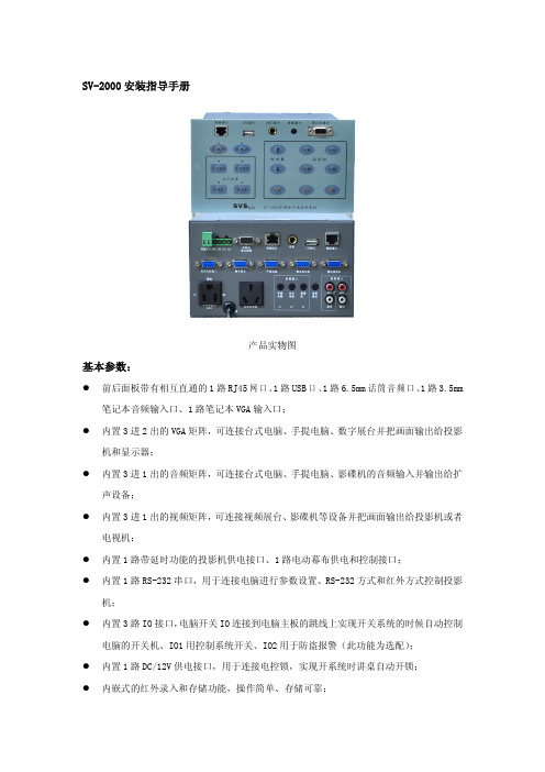
SV-2000安装指导手册产品实物图基本参数:�前后面板带有相互直通的1路RJ45网口、1路USB口、1路6.5mm话筒音频口、1路3.5mm 笔记本音频输入口、1路笔记本VGA输入口;�内置3进2出的VGA矩阵,可连接台式电脑、手提电脑、数字展台并把画面输出给投影机和显示器;�内置3进1出的音频矩阵,可连接台式电脑、手提电脑、影碟机的音频输入并输出给扩声设备;�内置3进1出的视频矩阵,可连接视频展台、影碟机等设备并把画面输出给投影机或者电视机;�内置1路带延时功能的投影机供电接口、1路电动幕布供电和控制接口;�内置1路RS-232串口,用于连接电脑进行参数设置、RS-232方式和红外方式控制投影机;�内置3路IO接口,电脑开关IO连接到电脑主板的跳线上实现开关系统的时候自动控制电脑的开关机、IO1用控制系统开关、IO2用于防盗报警(此功能为选配);�内置1路DC/12V供电接口,用于连接电控锁,实现开系统时讲桌自动开锁;�内嵌式的红外录入和存储功能,操作简单、存储可靠;�支持主输出音量的增减调节功能;�支持数据导入和导出功能,方便批量安装;一、线材准备1.投影机处需要布有三芯电源线、两芯控制线、VGA线、视频线各一根。
2.电动幕布处需要布有三芯电源线一根。
3.台式电脑和笔记本电脑处各需要有两边公头的VGA线一根、两边3.5mm接头的音频线一根。
4.如果是数字展台则需要有两边公头的VGA线一根,如果是视频展台则需要有两边莲花头视频线一根。
5.影碟机处需要有两边莲花头视频线一根、3.5mm接头转双莲花的音频线一根。
6.功放处需要有3.5mm接头转双莲花的音频线一根(具体视功放接口的不同而改动)。
二、安装中控1.安装方式为嵌入式,一般为直接嵌入在讲桌上。
2.本机的开孔参数示意图,注意开孔尺寸必须略大于机身尺寸,小于档板尺寸。
三、接线说明1.电动幕布接线,打开幕布电源线中的升降停控制盒,记下升、降、公共线的定义,剪去控制盒,把电源线延长进讲桌,对照本机电动幕接口上的标识接上美标电源头(本机有标配此电源接头,接线方法参照下图)。
CBS2000系统安装说明书

CBS2000系统安装说明书1、概述CBS2000系统是基于B/S结构的“在线监测数据管理和分析系统”,系统的安装涉及到环境配置、数据库安装、系统软件部署和接口安装与配置。
2、安装步骤2.1 环境配置①安装JDK1.5➢双击JDK1.5的安装程序进行安装➢如下图选择“我接受…”➢按步骤根据默认选项进行安装,直到如下完成安装界面➢单击“完成”,完成JDK安装②设置环境变量➢鼠标又击桌面上的“我的电脑”图标,选择“属性”打开如下窗体➢选择“高级”选项,单击“环境变量”➢在“系统变量”框选择“新建”,建一个新的环境变量➢在“变量名”中填写“JA V A_HOME”,“变量值”填写JDK的安装路径。
如:C:\Program Files\Java\jdk1.5.0_062.2 数据库安装CBS2000运行前要进行ORACLE的安装和配置。
①oracle安装➢解压Oracle.10g.for.Windows,单击“setup”进行安装,进入“Oracle Database 10g 安装”画面。
选中“高级安装”。
➢“下一步”进入“Oracle Universal Installer:指定文件位置”。
选择安装路径,在目标路径中选择安装路径。
(一般使用默认路径)➢“下一步”进入“Oracle Universal Installer:选择安装类型”。
选择“企业版”➢选择“下一步”进行安装,直到“Oracle Universal Installer:指定数据库方案的口令”。
选择“所有的帐户都使用同一个口令”,输入口令cbs2000。
➢单击“下一步”,继续安装,进入“Oracle Universal Installer:概要”。
➢单击“安装”,开始安装过程,大约半小时。
➢数据库创建完成时,显示“Database Configuration Assistant”窗口。
➢单击“口令管理”,进入“口令管理”窗口。
去掉“SCOTT”用户的“是否锁定帐户”的“√”,解锁“SCOTT”用户。
百威商业管理系统——简单安装教程及维护方法

百威商业管理系统——简单安装教程及维护方法(总13页)-CAL-FENGHAI.-(YICAI)-Company One1-CAL-本页仅作为文档封面,使用请直接删除百威商业管理系统简单安装教程及维护方法苏州新中天电脑科技有限公司1. 准备工作电脑上安装好操作系统98/2000/Xp/2003准备好百威商业管理软件安装文件(光盘文件、网上下载、硬盘拷贝)准备好百威商业管理软件加密狗准备好SQL Server 2000 安装文件各版本下载见下面Microsoft SQL Server 2000个人版下载链接适用于Windows 98/2000/XP 专业版操作系统Microsoft SQL Server 2000标准/企业/高级企业版下载链接 2000/2003 服务器版操作系统Microsoft SQL Server 2000 SP3 补丁下载链接 SQL Server 2000 SP4 补丁(推荐)下载链接注意:安装过程中最好不要断电,请做好稳定电源方面的措施!术语:单击:移动鼠标,在指定的位置,左键按一次右击:移动鼠标,在指定的位置,右键按一次双击:移动鼠标,在指定的位置,左键连按两次百威:深圳市智百威科技发展有限公司[ ]:为图片上的字符选择:移动鼠标,在指定的位置,左键按一次,勾选相应的选项框2. 下载说明安装好迅雷,在迅雷的悬浮窗上右击图表 1 迅雷选项图表 2 迅雷新建任务选择[确定],等待下载完成。
3. 安装微软Microsoft SQL Server 2000 以个人版为例:在下载的文件上,点击右键,解压下载文件运行目录里面的双击运行出现SQL安装界面图表 3 SQL安装界面过一会儿,进入参数设置界面,一直点击[下一步],点击8次或直到出现[服务帐户]窗口,选择[使用本地系统帐户],点击[下一步]图表 4 服务帐户出现[身份证模式],此处选择[混合模式],[空密码]图表 5 身份证模式注:●建议局域网用户选择此项,如果是连锁版用户一定要输入密码,切记!点击两次[下一步]就可以开始安装了,出现进度条,一直等到安装完成,点击[完成]图表 6 安装进度条图表 7 安装完成注:●windows 2000系统到此SQL就己安装完成,重启电脑或在开始菜单中启动SQL Server 服务即可进行百威软件安装。
- 1、下载文档前请自行甄别文档内容的完整性,平台不提供额外的编辑、内容补充、找答案等附加服务。
- 2、"仅部分预览"的文档,不可在线预览部分如存在完整性等问题,可反馈申请退款(可完整预览的文档不适用该条件!)。
- 3、如文档侵犯您的权益,请联系客服反馈,我们会尽快为您处理(人工客服工作时间:9:00-18:30)。
2.在“Hardware”选项里也可以看到控制器第一个 FC 物理端口是 Up 状态,但是没有对应的虚 拟子接口。这里也可以看出其 NPIV 模式是开启的:
37.完成后的目标卷状态如下,它是以 Raid5-9 方式放置数据:
38.同样方法可配置 Mirror,完成后的状态如下,注意卷图标的变化.
39.下面是配置卷迁移(Migrate)的向导,迁移完成后可选择删除源卷,而目的卷会自动代替源 卷映射给原主机:
最后,可在 Leader 控制器的串口命令行中,运行如下命令清除配置,恢复盘柜到出厂状态:
27.输入用于 iSCSI initiator 连接的 iSCSI target portal 的 IP 地址及其他配置,如 Vlan ID,MTU 等:
28.然后分别为每块控制器上的 iSCSI port 分配 IP:
29.完成后状态如下图示,注意两个 iSCSI 口的状态为 Up:
30.打开主机的 Server ManagerToolsiSCSI initiator:
3.创建服务器时,也能发现两张 HBA 卡:
命令执行完成后需要手工重启两个控制器.
补充测试一: SCv2020 DAS 直连测试
1.DAS 版本 SCv2000 的初始化过程及 MPIO 设置和前面文档里描述的 FC 的版本完全一样, 不再赘 述。本测试中将 R720 上的 SAS3.0 HBA 卡的两个口分别连到 SCv2020 两个控制器的第四个 SAS 口,所以看到如下图所示的 SAS Domain 信息:
5.接下来回到 Storage Client 中创建主机:
6.完成后在 Connectivity 中看得到详细连接信息,注意 Initiator 始终是和虚拟子接口建立的 连接:
7.接下来我们在 WIN2012 里找到从 SCv2020 分配的卷,初始化,格式化,然后从服务器往该卷拷 贝大文件。 其间我们如果手工断开服务器处于数据传输状态的网卡的网线, 发现其上的虚拟子口 会自动 failover 到另外控制器上的物理 iSCSI target 口上,文件拷贝在暂停二十多秒后自动 恢复,不会中断。
31.在 Discovery 选项中,添加 Discover Portal,即前面步骤 27 里分配的 SCv2000 iSCSI target portal 地址:
32.在 Targets 选项里可以看到以 SCv2020 两个控制器 iSCSI 物理口分别生成的虚拟接口的 IQN 为名字的 iSCSI target,点击 Connect 分别连接:
2.在“Hardware”选项里可以更清楚的看到虚拟子口和物理口的对应关系:
3.打开 WIN2012 的 iSCSI Initiator 属性菜单,在“Discovery”里添加 SCv2020 的 iSCSI target portal 地址(注意不是某个物理口地址):
4.在“Targets”里我们看到找到了两个虚拟子口 IQN 名字的两个 targets,点击 Connect 连入:
8.但是,在随后的测试中发现,如果拷贝文件过程中手工断开 SCv2020 上处于数据传输状态的 控制器对应的网口的线缆,其上的虚拟子口不会自动 failover 到另外控制器上的物理 iSCSI target 口上,导致现有的 iSCSI 连接断开,文件拷贝会中断。这时只有在 Storage Client 里 手工删掉原服务器,重新创建用剩下好的 iSCSI 虚拟子口连接的服务器,然后映射原卷,才可继 续使用。所以,在这种情况下,无法保证业务连续性!
16.打开后右击 Storage Center,选择 Edit Settings,可查看更改本系统的基本配置,如下图示:
17.比如自定义 Volume 创建向导,选择希望的 Replay profile 和 Storage Profile:
18.接下来创建一个卷并通过 FC SAN 分配给一台 W2012 主机.鼠标右击”Volumes”,选择新 建一个卷 , 即可打开向导 , 在创建过程中可根据需要选择合适的 Storage Profile,Replay Profile,回放的最小间隔时间可设为 5 分钟.
9.最后模拟控制器坏的场景,即在文件拷贝过程中,将处于数据传输状态的控制器手工拔出,此 时类似在前面步骤 7 里描述的情况,其物理口上的虚拟子口会自动 failover 到另外控制器上的 物理 iSCSI target 口上,文件拷贝在暂停二十多秒后自动恢复,不会中断。
补充测试三: SCv2020 FC 直连测试
35.同 SC4000/SC8000 一样,SCv2000 核心里带有 CMM 功能.选择一个卷,鼠标右击,选择 Local CopyCopy Volume,打开向导:
36.选择一个目标卷作为源卷 Copy 的目的地,如果没有,也可在该界面里点击 Create Volume 创建一新的卷.拷贝时还可包括源卷的回放点:
33.在 SCv2000 Storage Center 界面里打开 Create Server 向导,选择主机的 iSCSI initiator, 创建主机,同样注意主机操作系统类型的选择:
34.在 Storage Center 里分配一个卷给该主机,然后回到主机端,打开 Disk Management,重新 扫描后即能看到该卷,上线,初始化,格式化后即可正常使用.
21.鼠标右击刚创建的主机,选择”Map Volume to Server”,为该主机分配一个卷.
22.在作卷对主机映射配置时可以更改的所有参数如下:
23.进入 Win2012 主机的 Server ManagerToolsMPIO(如果没有该项则需要为本机添加 MPIO feature).
24.添加 Compellent 对应的 ID,如下图示,注意大小写和空格.完成后系统将提示重启以生效:
6.配置缺省管理员账号 Admin 的密码及邮箱,然后继续:
7.检查 Summary 信息,没有问题则点击”Apply Configuration”:
8.盘柜开始初始化过程:
9.接下来开始前端口 Fault Domain 的配置.Fault Domain 指连接在一台交换机上,Virtual Port 可以相互 failover 到其他物理端口的前端口的集合.如下图示的标准的 SAN 架构下,会 自动创建两个 Fault Domain:
SCv2000 基本安装与配置
本试验包含 SCv2000 初始化配置,通过 FC SAN 连接 Win2012R2(Datacenter Edition)服务 器和通过 iSCSI SAN 连接 Win2012R2 服务器三部分.试验中使用的型号是一台 8GBX4 FC 口 双控制器的 SCv2020(24X600GB SAS15K),Storage Center 版本号为 6.6.4.6, 光纤交换机为 Brocade6505,iSCSI 交换机为 PC6224. 文档末补充的直连测试中添加了一台 SAS3.0X4 端口双控制器的 SCv2020,一台 R720(安装 DELL SAS3.0 12Gb SAS HBA/Brocade825 HBA,操作系统为 WIN2012R2 Datacenter Edition) 。 1.从 DELL Compellent partner portal 上下载 Enterprise manager 2015,解压后运行其中的 Enterprise Manager Client setup 安装程序,安装 Dell Storage Client,我们需要用该客户端 完成 SCv2020 的初始化,并用其连接 SCv2020 Storage Center 做管理.
14.SupportAssist 需要的详细配置信息如下,完成后下一步,也可跳过,以后再配置.接下来会 自动检查系统是否需要升级,最后完成所有初始化配置:
15. 管理员可随时打开 DELL Storage Client, 选择 “Log in to a Storage Center or Data Collector”登录 SCv2000:
补充测试二: SCv2020 iSCSI 直连测试
1.我们启用 SCv2020 的 flex port 功能,将 R720 主板集成的双口千兆网卡分别直连到两个控制 器的万兆管理口上,打开 Storage Client,配置好 Flex Port Domain 1,如下图示。我们看到, 因为 SCv2000 系列只能支持 Virtual Port 模式,所以每个物理 iSCSI Target 口会生成一个虚 拟子口,用于和 initiator 建立连接。
4.在 WIN2012 的磁盘管理工具里,找到分配的 SCv2020 的卷,在属性里点击 MPIO,可以看到一 主一备的两条路径。这里,可根据需要调整 MPIO 策略,比如可以改为“failover only”.
5.接下来做路径 failover 的测试。从服务器上拷贝大文件到 SCv2020 的卷,其间将 Active 的 SAS 口的线断开, 我们看到原来的 standby 路径变成了 Active, 文件拷贝经过短暂暂停后继续进 行,没有中断。
10.完成后将显示创建的 Fault Domains 的详细信息,如下图示:
11.接下来完成时区及时间的配置:
12.配置 SMTP,然后下一步:
13.SupportAssist 许可协议.如果打开此功能,StorageCenter 将把系统配置信息,日志,性能数 据等相关信息收集后发给 DELL 技术支持,由此客户能够享受存储系统故障预防服务:
2. 在弹出的向导中选择 “Discover and Configure Uninitialized SCv2000 Series Storage Centers”:
