GIPC appendix Using Performance Charts
《公共建筑节能(绿色建筑)工程施工质量验收规范》DBJ50-234-2016
( 7 ) 本 规 范 第 16.2.10 条 依 据 国 家 标 准 《 太 阳 能 供 热 采 暖 工 程 技 术 规 范 》 GB50495-2009 第 5.3.5 条的规定。
(8)本规范第 3.4.4 条为绿色建筑工程涉及的建筑环境与资源综合利用子分部工程 验收方式的规定。
本规范由重庆市城乡建设委员会负责管理,由重庆市建设技术发展中心(重庆市建 筑节能中心)、重庆市绿色建筑技术促进中心负责具体技术内容解释。在本规范的实施 过程中,希望各单位注意收集资料,总结经验,并将需要修改、补充的意见和有关资料 交重庆市建设技术发展中心(重庆市渝中区牛角沱上清寺路 69 号 7 楼,邮编:400015, 电话:023-63601374,传真:023-63861277),以便今后修订时参考。
建设部备案号: J13144-2015
DB
重庆市工程建设标准 DBJ50-234-2016Leabharlann 公共建筑节能(绿色建筑)工程
施工质量验收规范
Code for acceptance of energy efficient public building(green building) construction
(3)本规范第 1.0.4、3.1.2、11.2.4、22.0.6、22.0.7 条内容分别依据国家标准《建 筑节能工程施工质量验收规范》GB50411-2007 第 1.0.5、3.1.2 条、11.2.3、15.0.5、15.0.5 条等强制性条文要求。
NI cDAQ
SPECIFICA TIONSNI cDAQ™-91844-Slot, Ethernet CompactDAQ ChassisDefinitionsWarranted specifications describe the performance of a model under stated operating conditions and are covered by the model warranty.Characteristics describe values that are relevant to the use of the model under stated operating conditions but are not covered by the model warranty.•Typical specifications describe the expected performance met by a majority of the models.•Nominal specifications describe parameters and attributes that may be useful in operation. Specifications are Typical unless otherwise noted.ConditionsSpecifications are valid at 25 °C unless otherwise noted.Analog InputInput FIFO size127 samples per slotMaximum sample rate1Determined by the C Series module or modules Timing accuracy250 ppm of sample rateTiming resolution212.5 nsNumber of channels supported Determined by the C Series module or modules 1Performance dependent on type of installed C Series module and number of channels in the task.2Does not include group delay. For more information, refer to the documentation for each C Series module.Analog OutputNumber of channels supportedHardware-timed taskOnboard regeneration16Non-regeneration Determined by the C Series module or modules Non-hardware-timed task Determined by the C Series module or modules Maximum update rateOnboard regeneration 1.6 MS/s (multi-channel, aggregate)Non-regeneration Determined by the C Series module or modules Timing accuracy50 ppm of sample rateTiming resolution12.5 nsOutput FIFO sizeOnboard regeneration8,191 samples shared among channels used Non-regeneration127 samples per slotAO waveform modes Non-periodic waveform,periodic waveform regeneration mode fromonboard memory,periodic waveform regeneration from hostbuffer including dynamic updateDigital Waveform CharacteristicsWaveform acquisition (DI) FIFOParallel modules511 samples per slotSerial modules63 samples per slotWaveform generation (DO) FIFOParallel modules2,047 samples per slotSerial modules63 samples per slotDigital input sample clock frequencyStreaming to application memory System-dependentFinite0 MHz to 10 MHz2| | NI cDAQ-9184 SpecificationsDigital output sample clock frequencyStreaming from application memory System-dependentRegeneration from FIFO0 MHz to 10 MHzFinite0 MHz to 10 MHzTiming accuracy50 ppmGeneral-Purpose Counters/TimersNumber of counters/timers4Resolution32 bitsCounter measurements Edge counting, pulse, semi-period, period,two-edge separation, pulse widthPosition measurements X1, X2, X4 quadrature encoding withChannel Z reloading; two-pulse encoding Output applications Pulse, pulse train with dynamic updates,frequency division, equivalent time sampling Internal base clocks80 MHz, 20 MHz, 100 kHzExternal base clock frequency0 MHz to 20 MHzBase clock accuracy50 ppmOutput frequency0 MHz to 20 MHzInputs Gate, Source, HW_Arm, Aux, A, B, Z,Up_DownRouting options for inputs Any module PFI, analog trigger, many internalsignalsFIFO Dedicated 127-sample FIFOFrequency GeneratorNumber of channels1Base clocks20 MHz, 10 MHz, 100 kHzDivisors 1 to 16 (integers)Base clock accuracy50 ppmOutput Any module PFI terminalNI cDAQ-9184 Specifications| © National Instruments| 3Module PFI CharacteristicsFunctionality Static digital input, static digital output, timinginput, and timing outputTiming output sources3Many analog input, analog output, counter,digital input, and digital output timing signals Timing input frequency0 MHz to 20 MHzTiming output frequency0 MHz to 20 MHzDigital TriggersSource Any module PFI terminalPolarity Software-selectable for most signalsAnalog input function Start Trigger, Reference Trigger,Pause Trigger, Sample Clock,Sample Clock TimebaseAnalog output function Start Trigger, Pause Trigger, Sample Clock,Sample Clock TimebaseCounter/timer function Gate, Source, HW_Arm, Aux, A, B, Z,Up_DownModule I/O StatesAt power-on Module-dependent. Refer to the documentationfor each C Series module.Network InterfaceNetwork protocols TCP/IP, UDPNetwork ports used HTTP:80 (configuration only), TCP:3580;UDP:5353 (configuration only), TCP:5353(configuration only); TCP:31415; UDP:7865(configuration only), UDP:8473 (configurationonly)Network IP configuration DHCP + Link-Local, DHCP, Static,Link-Local3Actual available signals are dependent on type of installed C Series module.4| | NI cDAQ-9184 SpecificationsHigh-performance data streams7Data stream types available Analog input, analog output, digital input,digital output, counter/timer input,counter/timer output, NI-XNET4Default MTU size1500 bytesJumbo frame support Up to 9000 bytesEthernetNetwork interface1000 Base-TX, full-duplex; 1000 Base-TX,half-duplex; 100 Base-TX, full-duplex;100 Base-TX, half-duplex; 10 Base-T,full-duplex; 10 Base-T, half-duplex Communication rates10/100/1000 Mbps, auto-negotiated Maximum cabling distance100 m/segmentPower RequirementsCaution The protection provided by the NI cDAQ-9184 chassis can be impaired ifit is used in a manner not described in the NI cDAQ-9181/9184/9188/9191 UserManual.Note Some C Series modules have additional power requirements. For moreinformation about C Series module power requirements, refer to the documentationfor each C Series module.Note Sleep mode for C Series modules is not supported in the NI cDAQ-9184.V oltage input range9 V to 30 VMaximum power consumption515 W4When a session is active, CAN or LIN (NI-XNET) C Series modules use a total of two data streams regardless of the number of NI-XNET modules in the chassis.5Includes maximum 1 W module load per slot across rated temperature and product variations.NI cDAQ-9184 Specifications| © National Instruments| 5Note The maximum power consumption specification is based on a fully populatedsystem running a high-stress application at elevated ambient temperature and withall C Series modules consuming the maximum allowed power.Power input connector 2 positions 3.5 mm pitch mini-combicon screwterminal with screw flanges, SauroCTMH020F8-0N001Power input mating connector Sauro CTF020V8, Phoenix Contact 1714977,or equivalentPhysical CharacteristicsWeight (unloaded)Approximately 643 g (22.7 oz)Dimensions (unloaded)178.1 mm × 88.1 mm × 64.3 mm(7.01 in. × 3.47 in. × 2.53 in.) Refer to thefollowing figure.Screw-terminal wiringGauge0.5 mm 2 to 2.1 mm2 (20 AWG to 14 AWG)copper conductor wireWire strip length 6 mm (0.24 in.) of insulation stripped from theendTemperature rating85 °CTorque for screw terminals0.20 N · m to 0.25 N · m (1.8 lb · in. to2.2 lb · in.)Wires per screw terminal One wire per screw terminalConnector securementSecurement type Screw flanges providedTorque for screw flanges0.20 N · m to 0.25 N · m (1.8 lb · in. to2.2 lb · in.)If you need to clean the chassis, wipe it with a dry towel.6| | NI cDAQ-9184 SpecificationsFigure 1. NI cDAQ-9184 Dimensions30.6 mm 47.2 mm Safety VoltagesConnect only voltages that are within these limits.V terminal to C terminal30 V maximum, Measurement Category IMeasurement Category I is for measurements performed on circuits not directly connected to the electrical distribution system referred to as MAINS voltage. MAINS is a hazardous liveNI cDAQ-9184 Specifications | © National Instruments | 7electrical supply system that powers equipment. This category is for measurements of voltages from specially protected secondary circuits. Such voltage measurements include signal levels, special equipment, limited-energy parts of equipment, circuits powered by regulatedlow-voltage sources, and electronics.Caution Do not connect the system to signals or use for measurements withinMeasurement Categories II, III, or IV.Note Measurement Categories CAT I and CAT O (Other) are equivalent. These testand measurement circuits are not intended for direct connection to the MAINsbuilding installations of Measurement Categories CAT II, CAT III, or CAT IV.Environmental-20 °C to 55 °C6Operating temperature (IEC 60068-2-1and IEC 60068-2-2)Caution To maintain product performance and accuracy specifications when theambient temperature is between 45 and 55 °C, you must mount the chassishorizontally to a metal panel or surface using the screw holes or the panel mount kit.Measure the ambient temperature at each side of the CompactDAQ system 63.5 mm(2.5 in.) from the side and 25.4 mm (1.0 in.) from the rear cover of the system. Forfurther information about mounting configurations, go to /info and enterthe Info Code cdaqmounting.-40 °C to 85 °CStorage temperature (IEC 60068-2-1 andIEC 60068-2-2)Ingress protection IP 30Operating humidity (IEC 60068-2-56)10% to 90% RH, noncondensingStorage humidity (IEC 60068-2-56)5% to 95% RH, noncondensingPollution Degree (IEC 60664)2Maximum altitude5,000 mIndoor use only.6When operating the NI cDAQ-9184 in temperatures below 0 °C, you must use the PS-15 powersupply or another power supply rated for below 0 °C.8| | NI cDAQ-9184 SpecificationsHazardous LocationsU.S. (UL)Class I, Division 2, Groups A, B, C, D, T4;Class I, Zone 2, AEx nA IIC T4Canada (C-UL)Class I, Division 2, Groups A, B, C, D, T4;Class I, Zone 2, Ex nA IIC T4Europe (ATEX) and International (IECEx)Ex nA IIC T4 GcShock and VibrationTo meet these specifications, you must direct mount the NI cDAQ-9184 system and affix ferrules to the ends of the terminal lines.Operational shock30 g peak, half-sine, 11 ms pulse (Tested inaccordance with IEC 60068-2-27. Test profiledeveloped in accordance withMIL-PRF-28800F.)Random vibrationOperating 5 Hz to 500 Hz, 0.3 g rmsNon-operating 5 Hz to 500 Hz, 2.4 g rms (Tested in accordancewith IEC 60068-2-64. Non-operating testprofile exceeds the requirements ofMIL PRF-28800F, Class 3.)Safety and Hazardous Locations StandardsThis product is designed to meet the requirements of the following electrical equipment safety standards for measurement, control, and laboratory use:•IEC 61010-1, EN 61010-1•UL 61010-1, CSA C22.2 No. 61010-1•EN 60079-0:2012, EN 60079-15:2010•IEC 60079-0: Ed 6, IEC 60079-15; Ed 4•UL 60079-0; Ed 6, UL 60079-15; Ed 4•CSA 60079-0:2011, CSA 60079-15:2012Note For UL and other safety certifications, refer to the product label or the OnlineProduct Certification section.NI cDAQ-9184 Specifications| © National Instruments| 9Electromagnetic CompatibilityThis product meets the requirements of the following EMC standards for electrical equipment for measurement, control, and laboratory use:•EN 61326-1 (IEC 61326-1): Class A emissions; Basic immunity•EN 55011 (CISPR 11): Group 1, Class A emissions•EN 55022 (CISPR 22): Class A emissions•EN 55024 (CISPR 24): Immunity•AS/NZS CISPR 11: Group 1, Class A emissions•AS/NZS CISPR 22: Class A emissions•FCC 47 CFR Part 15B: Class A emissions•ICES-001: Class A emissionsNote In the United States (per FCC 47 CFR), Class A equipment is intended foruse in commercial, light-industrial, and heavy-industrial locations. In Europe,Canada, Australia and New Zealand (per CISPR 11) Class A equipment is intendedfor use only in heavy-industrial locations.Note Group 1 equipment (per CISPR 11) is any industrial, scientific, or medicalequipment that does not intentionally generate radio frequency energy for thetreatment of material or inspection/analysis purposes.Note For EMC declarations and certifications, and additional information, refer tothe Online Product Certification section.CE ComplianceThis product meets the essential requirements of applicable European Directives, as follows:•2014/35/EU; Low-V oltage Directive (safety)•2014/30/EU; Electromagnetic Compatibility Directive (EMC)•2014/34/EU; Potentially Explosive Atmospheres (ATEX)Online Product CertificationRefer to the product Declaration of Conformity (DoC) for additional regulatory compliance information. To obtain product certifications and the DoC for this product, visit / certification, search by model number or product line, and click the appropriate link in the Certification column.10| | NI cDAQ-9184 SpecificationsEnvironmental ManagementNI is committed to designing and manufacturing products in an environmentally responsible manner. NI recognizes that eliminating certain hazardous substances from our products is beneficial to the environment and to NI customers.For additional environmental information, refer to the Minimize Our Environmental Impact web page at /environment. This page contains the environmental regulations and directives with which NI complies, as well as other environmental information not included in this document.Waste Electrical and Electronic Equipment (WEEE) EU Customers At the end of the product life cycle, all NI products must bedisposed of according to local laws and regulations. For more information abouthow to recycle NI products in your region, visit /environment/weee.电子信息产品污染控制管理办法(中国RoHS)中国客户National Instruments符合中国电子信息产品中限制使用某些有害物质指令(RoHS)。
PDA TR59中英文对照(利用统计学进行产品监控)

Technical Report No.59
制药技术的传播者 GMP理论的践行者
目录
1.0 INTRODUCTION 简介 ...................................................................................... 4 1.1 PURPOSE AND SCOPE 目的和范围 ................................................................... 4
例.............................................................................. 44
2
制药技术的传播者 GMP理论的践行者
In light of the increased focus on this topic, this PDA Task Force recognized the need to provide guidance to help companies identify and use statistical methods. The primary objective of this Task Force was to convey the appropriate use of statistical methods at a level most can understand. 鉴于人们对这一主题越来越重视,PDA 工作组认识到应该建立指南帮助公司识别和使用统计方法。 该工作组的基本目的是让大多数人能够适当应用统计方法。
【转】各类分析函数调用关系图的工具
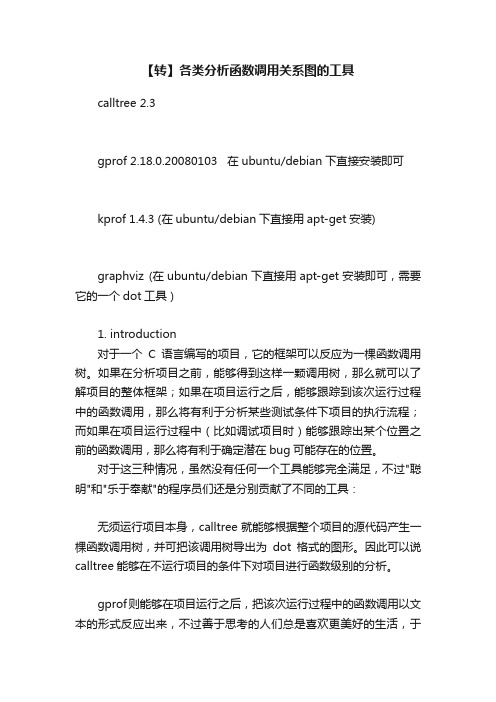
【转】各类分析函数调用关系图的工具calltree 2.3gprof 2.18.0.20080103 在ubuntu/debian下直接安装即可kprof 1.4.3 (在ubuntu/debian下直接用apt-get安装)graphviz (在ubuntu/debian下直接用apt-get安装即可,需要它的一个dot工具)1. introduction对于一个C语言编写的项目,它的框架可以反应为一棵函数调用树。
如果在分析项目之前,能够得到这样一颗调用树,那么就可以了解项目的整体框架;如果在项目运行之后,能够跟踪到该次运行过程中的函数调用,那么将有利于分析某些测试条件下项目的执行流程;而如果在项目运行过程中(比如调试项目时)能够跟踪出某个位置之前的函数调用,那么将有利于确定潜在bug可能存在的位置。
对于这三种情况,虽然没有任何一个工具能够完全满足,不过"聪明"和"乐于奉献"的程序员们还是分别贡献了不同的工具:无须运行项目本身,calltree就能够根据整个项目的源代码产生一棵函数调用树,并可把该调用树导出为dot格式的图形。
因此可以说calltree能够在不运行项目的条件下对项目进行函数级别的分析。
gprof则能够在项目运行之后,把该次运行过程中的函数调用以文本的形式反应出来,不过善于思考的人们总是喜欢更美好的生活,于是kprof产生了,它不仅可以辅助gprof更好的分析程序代码级别的运行情况,而且能够导出当前执行过程中的函数调用树,并同样可以把调用树导出为dot格式的图形。
gdb(Gnu DeBugger),这个应该很熟悉吧,它是一个调试工具。
它提供专门的backtrace命令来跟踪程序执行到某个位置(比如指定的断点处)之前的函数调用。
不过这个目前还是文本输出的,感兴趣的可以hack一下gdb,给它加上漂亮的输出。
上面提到了DOT格式的图形。
这个DOT[2]是什么呢?是graphviz[3]定义的一种图形描述语言,它可以通过graphviz提供的dot工具(安装graphviz之后就有了)把用DOT描述的图形转化为各种其他格式的图形。
dynamicreports 交叉表-概述说明以及解释

dynamicreports 交叉表-概述说明以及解释1.引言1.1 概述动态报告是一种高度可定制和自动化生成的报告生成工具,可以通过使用动态报告库来创建丰富多样的报告,包括但不限于交叉表。
在数据分析和数据可视化领域,交叉表是一种常用的工具,用于展示不同变量之间的关系以及它们对结果的影响。
本文将重点介绍dynamicreports库中的交叉表功能,该库是一个功能强大的Java报告生成库,提供了丰富的报告生成选项和灵活的报告布局。
它可以帮助开发人员轻松地生成精美的报告,并且具有良好的扩展性和可定制性。
在本文中,我们将首先介绍动态报告的基本概念,包括其原理和使用方法。
随后,我们将详细介绍dynamicreports库的特点和功能,以及它为创建交叉表所提供的支持。
我们将解释交叉表的概念和应用,并展示如何使用dynamicreports库来创建交叉表报告。
在文章的结论部分,我们将总结动态报告的优势,包括其在报告生成方面的灵活性和效率。
同时,我们还将对dynamicreports库中的交叉表功能进行评价,并探讨未来的发展方向。
通过本文的阅读,读者将能够全面了解动态报告和交叉表的基本概念,以及如何使用dynamicreports库来创建交叉表报告。
同时,读者还可以深入了解该库的特点和功能,并探索其在数据分析和报告生成领域的应用价值。
1.2 文章结构本篇长文将按照以下结构进行组织和论述:第一部分是引言部分,主要对本文的研究对象进行概述,并介绍了文章的整体结构和目的。
引言部分将介绍动态报告和交叉表的基本概念,以及本文的研究目的。
第二部分是正文部分,主要围绕动态报告和交叉表展开讨论。
首先,将介绍动态报告的基本概念,包括其用途和特点。
然后,将详细介绍dynamicreports库,包括其功能和应用场景。
接着,将介绍交叉表的概念和应用,以及交叉表在数据分析中的重要性。
最后,将详细介绍dynamicreports库中的交叉表功能,包括如何创建和定制交叉表,以及如何使用它们进行数据分析和可视化。
8款好用的开源报表工具
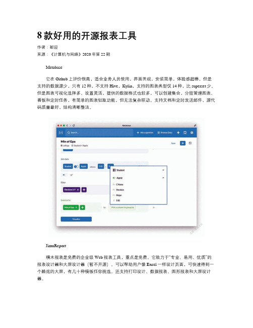
8款好用的开源报表工具作者:都迎来源:《计算机与网络》2020年第22期Metabase它在Github上评价很高,适合业务人员使用,界面美观,安装简单,体验感超棒。
但是支持的数据源少,只有12种,不支持Hive,Kylin,支持的图表类型仅14种,比superset少。
但是图表可视化选择多、设置灵活,提供的数据格式也较多,可以创建集合,分组管理图表、看板和定时任务,有简单的图表钻取功能,但无法复杂联动。
支持文档和定时发送邮件,源代码质量最好,结构清晰整洁。
JimuReport積木报表是免费的企业级Web报表工具,重点是免费。
它致力于“专业、易用、优质”的报表设计器和大屏设计器(暂不开源)。
可以帮助用户像Excel一样设计页面,可快速得到一个酷炫的大屏,有几十种模板任你挑选。
还支持打印设计、数据报表、图形报表和大屏设计器。
UReport2UReport2是第一款基于Apache-2.0协议开源的中式报表引擎,主打高性能的Java报表引擎,提供完善的基于网页的报表设计器,各种复杂的中式报表都能快速完成。
在UReport2中,提供了全新的基于网页的报表设计器,这方便了很多人,可以在各种主流浏览器运行(IE 浏览器除外),打开浏览器就能做出成各种复杂报表的设计制作。
EasyReportEasyReport听名字就知道它一定简单易用,它是一个Web报表工具,主要是把SQL语句查询出的行列结构转换成HTML表格(Table),而且支持表格的跨行与跨列。
同时还能Excel 导出、图表显示及固定表头与左边列的功能。
Reportico是一个报表设计工具,深受用户喜爱,它也是免费的。
可用来设计报表、创建报表菜单和配置,支持图形、分组、下钻、表达式处理和数据转换,可导出HTML,PDF,CSV格式,可通过CSS修改报表外观。
Superset它适合开发或者分析人员做好看板,业务人员浏览看板数据,业务人员可以自行编辑图表。
google-wide-profiling
..........................................................................................................................................................................................................................G OOGLE-W IDE P ROFILING:A C ONTINUOUS P ROFILINGI NFRASTRUCTURE FOR D ATA C ENTERS..........................................................................................................................................................................................................................G OOGLE-W IDE P ROFILING(GWP),A CONTINUOUS PROFILING INFRASTRUCTURE FORDATA CENTERS,PROVIDES PERFORMANCE INSIGHTS FOR CLOUD APPLICATIONS.W ITHNEGLIGIBLE OVERHEAD,GWP PROVIDES STABLE,ACCURATE PROFILES AND ADATACENTER-SCALE TOOL FOR TRADITIONAL PERFORMANCE ANALYSES.F URTHERMORE,GWP INTRODUCES NOVEL APPLICATIONS OF ITS PROFILES,SUCH AS APPLICATION-PLATFORM AFFINITY MEASUREMENTS AND IDENTIFICATION OF PLATFORM-SPECIFIC,MICROARCHITECTURAL PECULIARITIES.......As cloud-based computing growsin pervasiveness and scale,understanding data-center applications’performance and utiliza-tion characteristics is critically important, because even minor performance improve-ments translate into huge cost savings.Tradi-tional performance analysis,which typically needs to isolate benchmarks,can be too com-plicated or even impossible with modern datacenter applications.It’s easier and more representative to monitor datacenter applica-tions running on live traffic.However,applica-tion owners won’t tolerate latency degradations of more than a few percent,so these tools must be nonintrusive and have minimal overhead. As with all profiling tools,observer distortion must be minimized to enable meaningful analysis.(For additional information on re-lated techniques,see the‘‘Profiling:From sin-gle systems to data centers’’sidebar.)Sampling-based tools can bring overhead and distortion to acceptable levels,so they’re uniquely qualified for performance monitor-ing in the data center.Traditionally,sam-pling tools run on a single machine,monitoring specific processes or the systemas a whole.Profiling can begin on demandto analyze a performance problem,or it canrun continuously.1Google-Wide Profiling can be theoreti-cally viewed as an extension of the DigitalContinuous Profiling Infrastructure(DCPI)1to data centers.GWP is a continu-ous profiling infrastructure;it samples acrossmachines in multiple data centers and col-lects various events—such as stack traces,hardware events,lock contention profiles,heap profiles,and kernel events—allowingcross-correlation with job scheduling data,application-specific data,and other informa-tion from the data centers.GWP collects daily profiles from severalthousand applications running on thousandsof servers,and the compressed profileGang RenEric TuneTipp MoseleyYixin ShiSilvius RusRobert HundtGoogle0272-1732/10/$26.00 c2010IEEE Published by the IEEE Computer Society ...................................................................65database grows by several Gbytes every day.Profiling at this scale presents significant challenges that don’t exist for a single ma-chine.Verifying that the profiles are correct is important and challenging because the workloads are dynamic.Managing profiling overhead becomes far more important as well,as any unnecessary profiling overhead can cost millions of dollars in additional resources.Finally,making the profile data universally accessible is an additional chal-lenge.GWP is also a cloud application,with its own scalability and performance issues.With this volume of data,we can answer typical performance questions about datacen-ter applications,including the following:What are the hottest processes,rou-tines,or code regions?How does performance differ across software versions?Which locks are most contended? Which processes are memory hogs?Does a particular memory allocationscheme benefit a particular class of applications?What is the cycles per instruction (CPI)for applications across platforms?Additionally,we can derive higher-level data to more complex but interesting questions,such as which compilers were used for appli-cations in the fleet,whether there are more 32-bit or 64-bit applications running,and how much utilization is being lost by subop-timal job scheduling.InfrastructureFigure 1provides an overview of the en-tire GWP system.CollectorGWP samples in two dimensions.At any moment,profiling occurs only on a small subset of all machines in the fleet,and event-based sampling is used at the machine level.Sampling in only one dimension would..............................................................................................................................................................................................Profiling:From single systems to data centersFrom gprof 1to Intel VTune (/en-us/intel-vtune),profiling has long been standard in the development process.Most profiling tools focus on a single execution of a single program.As computing systems have evolved,understanding the bigger picture across multiple machines has become increasingly important.Continuous,always-on profiling became more important with Morph and DCPI for Digital UNIX.Morph uses low overhead system-wide sam-pling (approximately 0.3percent)and binary rewriting to continuously evolve programs to adapt to their host architectures.2DCPI gathers much more robust profiles,such as precise stall times and causes,and focuses on reporting information to users.3OProfile,a DCPI-inspired tool,collects and reports data much in the same way for a plethora of architectures,though it offers less sophisti-cated analysis.GWP uses OProfile ()as a profile source.High-performance computing (HPC)shares many profiling challenges with cloud computing,because profilers must gather repre-sentative samples with minimal overhead over thousands of nodes.Cloud computing has additional challenges—vastly disparate applica-tions,workloads,and machine configurations.As a result,different profil-ing strategies exist for HPC and cloud computing.HPCToolkit uses lightweight sampling to collect call stacks from optimized programs and compares profiles to identify scaling issues as parallelism increases.4Open|SpeedShop ()provides similar func-tionality.Similarly,Upshot 5and Jumpshot 6can analyze traces (suchas MPI calls)from parallel programs but aren’t suitable for continuous profiling.References1.S.L.Graham,P.B.Kessler,and M.K.Mckusick,‘‘Gprof:A Call Graph Execution Profiler,’’piler Con-struction (CC 82),ACM Press,1982,pp.120-126.2.X.Zhang et al.,‘‘System Support for Automatic Profiling and Optimization,’’Proc.16th ACM Symp.Operating Systems Principles (SOSP 97),ACM Press,1997,pp.15-26.3.J.M.Anderson et al.,‘‘Continuous Profiling:Where Have All the Cycles Gone?’’Proc.16th ACM Symp.Operating Sys-tems Principles (SOSP 97),ACM Press,1997,pp.357-390.4.N.R.Tallent et al.,‘‘Diagnosing Performance Bottlenecks in Emerging Petascale Applications,’’Proc.Conf.High Perfor-mance Computing Networking,Storage and Analysis (SC 09),ACM Press,2009,no.51.5.V.Herrarte and E.Lusk,Studying Parallel Program Behavior with Upshot,tech.report,Argonne National Laboratory,1991.6.O.Zaki et al.,‘‘Toward Scalable Performance Visualization with Jumpshot,’’Int’l J.High Performance Computing Appli-cations,vol.13,no.3,1999,pp.277-288.....................................................................66IEEE MICRO...............................................................................................................................................................................................D ATACENTER C OMPUTINGbe unsatisfactory;if event-based profiling were active on every machine all the time, at a normal event-sampling rate,we would be using too many resources across the fleet.Alternatively,if the event-sampling rate is too low,profiles become too sparse to drill down to the individual machine level.For each event type,we choose a sampling rate high enough to provide mean-ingful machine-level data while still minimizing the distortion caused by the profiling on critical applications.The system has been actively profiling nearly all machines at Google for several years with only rare complaints of system interference.A central machine database manages all machines in the fleet and lists every machine’s name and basic hardware characteristics.The GWP profile collector periodically gets a list of all machines from that database and selects a random sample of machines from that pool. The collector then remotely activates profil-ing on the selected machines and retrieves the results.It retrieves different types of sampled profiles sequentially or concurrently,depending on the machine and event type. For example,the collector might gather hardware performance counters for several seconds each,then move on to profiling for lock contention or memory allocation.It takes a few minutes to gather profiles for a specific machine.For robustness,the GWP collector is a distributed service.It helps improve availabil-ity and reduce additional variation from the collector itself.To minimize distortion on the machines and the services running on them,the collector monitors error conditions and ceases profiling if the failure rate reaches a predefined threshold.Aside from the collec-tor,we monitor all other GWP components to ensure an always-on service to users.On the top of the two-dimensional sam-pling approach,we apply several techniques to further reduce the overhead.First,we mea-sure the event-based profiling overhead on a set of benchmark applications and then con-servatively set the maximum rates to ensure the overhead is always less than a few percent. Second,we don’t collect whole call stacks for the machine-wide profiles to avoid the high overhead associated with unwinding(but we collect call stacks for most server profiles at lower sampling frequencies).Finally,wesave the profile and metadata in their raw for-mat and perform symbolization on a separateset of machines.As a result,the aggregatedprofiling overhead is negligible—less than0.01percent.At the same time,the derivedprofiles are still meaningful,as we show inthe‘‘Reliability analysis’’section.Profiles and profiling interfacesGWP collects two categories of profiles:whole-machine and per-process.Whole-machine profiles capture all activities happeningon the machine,including user applications,the kernel,kernel modules,daemons,and other background jobs.The whole-machine profiles include hardware perfor-mance monitoring(HPM)event profiles,kernel event traces,and power measurements.Users without root access cannot directlyinvoke most of the whole-machine profilingsystems,so we deploy lightweight daemonson every machine to let remote users(suchas GWP collectors)access those profiles.The daemons act as gate keepers to controlaccess,enforce sampling rate limits,and col-lect system variables that must be synchron-ized with the profiles.Figure1.An overview of the Google-Wide Profiling(GWP)infrastructure.The whole system consists of collector,symbolizer,profile database,Web server,and other components.....................................................................J ULY/A UGUST201067We use OProfile ()to collect HPM event profiles.OProfile is a system-wide profiler that uses HPM to gen-erate event-based samples for all running binaries at low overhead.To hide the hetero-geneity of events between architectures,we define some generic HPM events on top of the platform-specific events,using an approach similar to PAPI.2The most com-monly used generic events are CPU cycles,retired instructions,L1and L2cache misses,and branch mispredictions.We also provide access to some architecture-specific events.Although the aggregated profiles for those events are biased to specific architectures,they provide useful information for machine-specific scenarios.In addition to whole-machine profiles,we collect various types of profiles from most applications running on a machine using the Google Performance Tools (/p/google-perftools).Most appli-cations include a common library that enables process-wide stacktrace-attributed profiling mechanisms for heap allocation,lock contention,wall time and CPU time,and other performance metrics.The com-mon library includes a simple HTTP server linked with handlers for each type of profiler.A handler accepts requests from remote users,activates profiling (if it’s not already active),and then sends the profile data back.The GWP collector learns from the cluster-wide job management system what applica-tions are running on a machine and on which port each can be contacted for remote profiling invocation.A machine lacking re-mote profiling support has some programs,which the per-process profiling doesn’t cap-ture.However,these are few;comparison with system-wide profiles shows that remote per-process profiling captures the vast major-ity of Google’s programs.Most programs’users have found profiling useful or unobtru-sive enough to leave them enabled.Together with profiles,GWP collects other information about the target machine and applications.Some of the extra information is needed to postprocess the collected profiles,such as a unique identifier for each running binary that can be correlated across machines with unstripped versions for offline symboliza-tion.The rest are mainly used to tag theprofiles so that we later correlate the profiles with job,machine,or datacenter attributes.Symbolization and binary storageAfter collection,the Google File System (GFS)stores the profiles.3To provide mean-ingful information,the profiles must corre-late to source code.However,to save network bandwidth and disk space,applica-tions are usually deployed into data centers without any debug or symbolic information,which can make source correlation impossi-ble.Furthermore,several applications,such as Java and QEMU,dynamically generate and execute code.The code is not available offline and can therefore no longer be sym-bolized.The symbolizer must also symbolize operating system kernels and kernel loadable modules.Therefore,the symbolization process be-comes surprisingly complicated,although it’s usually trivial for single-machine profil-ing.Various strategies exist to obtain binaries with debug information.For example,we could try to recompile all sampled applica-tions at specific source milestones.However,it’s too resource-intensive and sometimes im-possible for applications whose source isn’t readily available.An alternative is to persis-tently store binaries that contain debug infor-mation before they’re stripped.Currently,GWP stores unstripped binaries in a global repository,which other services use to symbolize stack traces for automated failure reporting.Since the binaries are quite large and many unique binaries exist,symbolization for a single day of profiles would take weeks if run sequen-tially.To reduce the result latency,we dis-tribute symbolization across a few hundred machines using MapReduce.4Profile storageOver the past years,GWP has amassed several terabytes of historical performance data.GFS archives the entire performance logs and corresponding binaries.To make the data useful and accessible,we load the samples into a read-only dimensional data-base that is distributed across hundreds of machines.That service is accessible to all users for ad hoc queries and to systems for automated analyses.....................................................................68IEEE MICRO...............................................................................................................................................................................................D ATACENTER C OMPUTINGThe database supports a subset of SQL-like semantics.Although the dimensional database is well suited to perform queries that aggregate over the large data set,some individual queries can take tens of seconds to complete.Fortunately,most queries are seen frequently,so the profile server uses ag-gressive caching to hide the database latency. User interfacesFor most users,GWP deploys a webserver to provide a user interface on top of the pro-file database.This makes it easy to access profile data and construct ad hoc queries for the traditional use of application profiles (with additional freedom to filter,group,and aggregate profiles differently).Query view.Several visual interfaces retrieve information from the profile database,and all are navigable from a web browser.The primary interface(see Figure2)displays the result entries,such as functions or exe-cutables,that match the desired query parameters.This page supplies links that let users refine the query to more specific data.For example,the user can restrict the query to only report samples for a specific executable collected within a desired time period.Additionally,the user can modify or refine any of the parameters to the current query to create a custom profile view.The GWP homepage has links to display the top results,Google-wide,for each perfor-mance metric.Call graph view.For most server profile samples,the profilers collect full call stacks with each sample.Call stacks are aggregatedto produce complete dynamic call graphs for a given profile.Figure3shows an exam-ple call graph.Each node displays the func-tion name and its percentage of samples, and the nodes are shaded based on this per-centage.The call graph is also displayed through the web browser,via a Graphviz plug-in.Source annotation.The query and call graph views are useful in directing users to specific functions of interest.From there,GWP pro-vides a source annotation view that presents the original source file with a header describing overall profile information aboutthe file and a histogram bar showing the rel-ative hotness of each source file line.Becausedifferent versions of each file can exist insource repositories and branches,we retrievea hash signature from the repository for eachsource file and aggregate samples on fileswith identical signatures.Profile data API.In addition to the web-server,we offer a data-access API to readprofiles directly from the database.It’smore suitable for automated analyses thatmust process a large amount of profile(a)(b)Figure2.An example query view:an application-level profile(a)and afunction-level profile(b).....................................................................J ULY/A UGUST201069data (such as reliability studies)offline.We store both raw profiles and symbolized pro-files in ProtocolBuffer formats (/apis/protocolbuffers).Advanced users can access and reprocess them using their preferred programming language.Application-specific profilingAlthough the default sampling rate is highenough to derive top-level profiles with high confidence,GWP might not collect enough samples for applications that consume rela-tively few cycles Google-wide.Increasing the overall sampling rate to cover those pro-files is too expensive because they’re usually sparse.Therefore,we provide an extension to GWP for application-specific profiling on the cloud.The machine pool for applica-tion-specific profiling is usually much smaller than GWP,so we can achieve a high sampling rate on those machines for the specific application.Several application teams at Google use application-specific profiling to continuously monitor their applications running on the fleet.Application-specific profiling is generic and can target any specific set of machines.For example,we can use it to profile a set of machines deployed with the newest kernel version.We can also limit the profiling dura-tion to a small time period,such as the appli-cation’s running time.It’s useful for batch jobs running on data centers,such as MapRe-duce,because it facilitates collecting,aggre-gating,and exploring profiles collected from hundreds or thousands of their workers.Reliability analysisTo conduct continuous profiling on data-center machines serving real traffic,extremely low overhead is paramount,so we sample in both time and machine dimensions.Sam-pling introduces variation,so we must mea-sure and understand how sampling affects the profiles’quality.But the nature of data-center workloads makes this difficult;their behavior is continually changing.There’s no direct way to measure the datacenter applications’profiles’representativeness.In-stead,we use two indirect methods to evalu-ate their soundness.First,we study the stability of aggregated profiles themselves using several different metrics.Second,we correlate profiles with the performance data from other sources to cross-validate both.Stability of profilesWe use a single metric,entropy,to mea-sure a given profile’s variation.In short,en-tropy is a measure of the uncertainty associated with a random variable,which in this case is profile samples.The entropy H of a profile is defined as H W ðÞ¼ÀX n i ¼1p x i ðÞlog p x i ðÞðÞwhere n is the total number of entries in the profile and p (x )is the fraction of profile samples on the entry x .5In general,a high entropy implies a flat profile with many samples.A low entropy usually results from a small number of sam-ples or most samples being concentrated to few entries.We’re not concerned with en-tropy itself.Because entropy is like the signa-ture in a profile,measuring the inherentFigure 3.An example dynamic call graph.Function names are intentionally blurred.....................................................................70IEEE MICRO...............................................................................................................................................................................................D ATACENTER C OMPUTINGvariation,it should be stable between repre-sentative profiles.Entropy doesn’t account for differences between entry names.For example,a func-tion profile with x percent on foo and y per-cent on bar has the same entropy as a profile with y percent on foo and x percent on bar .So,when we need to identify the changes on the same entries between profiles,we cal-culate the Manhattan distance of two profiles by adding the absolute percentage differences between the top k entries,defined asM X ;Y ðÞ¼X k i ¼1p x x i ðÞÀp y x i ðÞ where X and Y are two profiles,k is the num-ber of top entries to count,and p y (x i )is 0when x i is not in Y .Essentially,the Manhat-tan distance is a simplified version of relative entropy between two profiles.Profiles’entropy.First,we compare the entropies of application-level profiles where samples are broken down on individ-ual applications.Figure 2a shows an exam-ple of such an application-level profile.Figure 4shows daily application-level profiles’entropies for a series of dates,to-gether with the total number of profilesamples collected for each date.Unless speci-fied,we used CPU cycles in the study,and our conclusions also apply to the other types.As the graph shows,the entropy of daily application-level profiles is stable be-tween dates,and it usually falls into a small interval.The correlation between the num-ber of samples and the profile’s entropy is loose.Once the number of samples reaches some threshold,it doesn’t necessarily lead to a lower entropy,partly because GWP sometimes samples more machines than nec-essary for daily application-level profiles.This is because users frequently must drill down to specific profiles with additional fil-ters on certain tags,such as application names,which are a small fraction of all pro-files collected.We can conduct similar analysis on an application’s function-level profile (for ex-ample,the application in Figure 2b).The re-sult,shown in Figure 5a,is from an application whose workload is fairly stable when aggregating from many clients.Its entropy is actually more stable.It’s interest-ing to analyze how entropy changes among machines for an application’s function-level profiles.Unlike the aggregated profiles across machines,an application’s per-machine profiles can vary greatly in termsFigure 4.The number of samples and the entropy of daily application-level profiles.The primary y -axis (bars)is the total number of profile samples.The secondary y -axis (line)is the entropy of the daily application-level profile.....................................................................J ULY /A UGUST 201071Figure 5.Function-level profiles.The number of samples and the entropy for a single application (a).The correlation between the number of samples and the entropy for all per-machine profiles (b).....................................................................72IEEE MICRO...............................................................................................................................................................................................D ATACENTER C OMPUTINGof number of samples.Figure5b plots the relationship between the number of sam-ples per machine and the entropy of func-tion-level profiles.As expected,when the total number of samples is small,the pro-file’s entropy is also small(limited by the maximum possible uncertainty).But once the threshold is reached at the maximum number of samples,the entropy becomes stable.We can observe two clusters from the graph;some entropies are concentrated between5.5and6,and the others fall be-tween4.5and5.The application’s two be-havioral states can explain the two clusters. We’ve seen various clustering patterns on different applications.The Manhattan distance between profiles.We use the Manhattan distance to study the variation between profiles considering the changes on entry name,where smaller distance implies less variation.Figure6a illustrates the Manhattan distance between the daily application-level profiles for a series of dates.The results from the Man-hattan distances for both application-level and function-level profiles are similar to the results with entropy.In Figure6b,we plot the Manhattan dis-tance for several profile types,leading to two observations:In general,memory and thread profiles have smaller distances,and their varia-tions appear less correlated with theother profiles.Server CPU time profiles correlate with HPM profiles of cycles and instructionsin terms of variations,which couldimply that those variations resulted nat-urally from external reasons,such asworkload changes.To further understand the correlation be-tween the Manhattan distance and the num-ber of samples,we randomly pick a subset of machines from a specific machine set and then compute the Manhattan distance of the selected subset’s profile against the whole set’s profile.We could use a power function’s trend line to capture the change in the Man-hattan distance over the number of samples. The trend line roughly approximates a square root relationship between the distance and thenumber of samples,M XðÞ¼C=ffiffiffiffiffiffiffiffiffiffiffiffiN XðÞpwhere N(X)is the total number of samplesin a profile and C is a constant that dependson the profile type.Derived metrics.We can also indirectlyevaluate the profiles’stability by computingsome derived metrics from multiple pro-files.For example,we can derive CPIfrom HPM profiles containing cycles andretired instructions.Figure7shows thatthe derived CPI is stable across dates.Notsurprisingly,the daily aggregated profiles’CPI falls into a small interval between1.7and1.8for those days.Comparing with other sourcesBeyond measuring profiles’stabilityacross dates,we also cross-validate the pro-files with performance and utilization datafrom other Google sources.One example isthe utilization data that the data center’smonitoring system collects.Unlike GWP,the monitoring system collects data from allmachines in the data center but at a coarsergranularity,such as overall CPU utilization.Its CPU utilization data,in terms of core-seconds,matches the measurement fromGWP’s CPU cycles profile with the follow-ing formula:CoreSeconds¼Cycles*SamplingRatemachine*SamplingPeriod/CPUFrequencyaverageProfile usesIn each profile,GWP records the samplesof interesting events and a vector of associ-ated information.GWP collects roughly adozen events,such as CPU cycles,retiredinstructions,L1and L2cache misses,branchmispredictions,heap memory allocations,and lock contention time.The sample defi-nition varies depending on the eventtype—it can be CPU cycles or cache misses,bytes allocated,or the sampled thread’s lock-ing time.Note that the sample must benumeric and capable of aggregation.The associated vector contains informationsuch as application name,function name,....................................................................J ULY/A UGUST201073。
利用vmstat+gnuplot+python脚本生成CPU和内存使用率图表
利用vmstat+gnuplot+python脚本生成CPU和内存使用率图表最近接触了 gnuplot 这个不错的工具,虽然生成图表的功能可以通过excel 容易的实现,但是在linux命令行下可以跟其他工具配合,轻松实现”自动化”。
vmstat 可以不断的显示linux 系统的 CPU/内存以及 io 的使用情况: vmstat 2 1000 表示每俩秒显示一次系统各种资源消耗情况,一共执行1000 次。
于是做了个比较简单丑陋的python脚本,格式化vmstat 的输出数据并利用gnuplot 生成图表—脚本中实际上是调用测试web server 压力的工具autobench 对gnuplot 的一个再封装脚本bench2png,生成完以后用sz 命令下载到本地,然后删除服务器上的文件。
gnuplot 的用法后面再整理下。
### 遍历当前目录下的文件fileList = os.listdir(path)for file in fileList:# 文件名中没有 vmstat 则不处理if file.find('vmstat') < 0:continue;# 只处理后缀 .txt 或者 .log 的文件if file[-4:] != '.txt'and file[-4:] != '.log':continue# 如果对应的 tsv 文件不存在, 则生成tsvFile = file[0:-4] + '.tsv'if not os.path.exists(path + tsvFile):fileHandle = open(path + file);# 生成 tsv 文件fileContent = ''i = 0header = ''for line in fileHandle.readlines():# 保证每行开始都一样:至少有一个空格line = '' + line# 如果该行存在 procs 则不处理if line.find('procs') > -1:continue# 前 10 行出现 cache 字符表明是列说明,则保留if line.find('cache') > -1and i > 10:continue# 替换字符line = re.sub(r"\n +", "\n", line)# 替换各种换行回车为 \n ,有一个值得改进的机制就是最好能够通过python 脚本内部调用 vmstat 而不是去分析 vmstat 的输出结果,不过作为我第二个实用 python 脚本,感觉还是不错了 :) 下面是生成图效果:One Response to “利用 vmstat+gnuplot+python脚本生成CPU 和内存使用率图表”。
程序性能分析与优化实战
程序性能分析与优化实战随着计算机技术的日益发展,企业和个人所面临的计算任务也越来越复杂,其中最重要的问题之一就是程序的性能。
性能分析和优化是一项非常重要的工作,可以帮助程序员更好地理解和优化程序。
本文将介绍一些程序性能分析和优化的实践技巧。
1. 程序性能分析程序性能分析是为了找出程序中潜在的瓶颈,以便优化程序性能。
常用的程序性能分析工具包括Gprof、Valgrind和Perf等,它们都提供了很多详细的性能数据和报告,可以帮助程序员快速定位性能问题的原因。
下面介绍一些常见的性能分析方法。
1.1 Gprof分析GNU Profiler (Gprof)是GNU工具包中的一个分析器,用于分析程序的性能瓶颈。
它使用计数器来记录程序在每个子程序内的运行时间,并生成图形化报告。
以下是使用Gprof进行性能分析的步骤:- 编译源代码时加上-g参数- 运行程序并生成gmon.out文件- 使用Gprof工具分析gmon.out文件1.2 Valgrind分析Valgrind是一个强大的开源工具包,其主要功能是检测程序运行时的内存泄漏和错误。
Valgrind通过模拟CPU执行,可以对程序进行全面的性能分析。
下面是使用Valgrind进行性能分析的步骤:- 编译源代码时加上-g参数和-fno-omit-frame-pointer参数- 运行程序并使用Valgrind工具进行分析1.3 Perf分析Performance Counters for Linux (Perf)是Linux内核中的一个性能分析工具,通过性能事件统计器来记录程序执行过程中的函数调用情况、CPU占用率等信息,可以非常详细地分析程序的性能问题。
以下是使用Perf进行性能分析的步骤:- 使用perf record命令开始记录执行信息- 使用perf report命令查看报告2. 程序性能优化性能优化是为了提高程序的执行效率,减少程序所占用的计算资源。
chartles 用法

chartles 用法Chartles是一款功能强大的数据可视化工具,它可以帮助用户创建各种图表,从而更好地展示数据。
在本文中,我们将介绍Chartles的用法和一些基本功能。
要开始使用Chartles,您需要下载和安装它的应用程序。
一旦安装完成,您可以通过打开应用程序来开始使用它。
Chartles支持多种图表类型,包括柱状图、折线图、饼图、散点图等等。
您可以根据数据的类型和需求选择适合的图表类型。
要创建一个图表,您需要提供相应的数据。
您可以手动输入数据,也可以将数据导入自己的电子表格或数据库中。
一旦数据加载完成,您可以开始设置和调整图表的参数。
Chartles提供了直观的界面,使您能够轻松地自定义和调整图表的外观和样式。
您可以更改图表的标题、颜色、字体、标签等。
此外,您还可以调整坐标轴、网格线和图例等元素,以便更好地呈现数据。
一旦图表设置完成,您可以对其进行预览,并进行必要的修改和调整。
Chartles还支持在图表中添加趋势线、数据标记和注释等功能,以便更详细地展示数据。
完成图表设计后,您可以将其保存为图像文件或PDF文档,以便与他人共享或在报告和演示中使用。
除了创建图表,Chartles还提供了一些高级功能,如数据筛选、数据排序、数据聚合等。
这些功能可以帮助您更好地分析和理解数据。
Chartles是一款功能强大且易于使用的数据可视化工具,它可以帮助您创建各种类型的图表,并以直观的方式展现数据。
无论您是数据分析师、市场营销人员还是学生,Chartles都是您展示数据的理想选择。
_tiddata 详解 -回复
_tiddata 详解-回复什么是_tiddata?_tiddata是_gambolputty_实时分析系统中的一个关键概念,用于管理和存储分析任务的数据。
_gambolputty是一个开源的实时大数据分析系统,旨在帮助用户高效地实时分析和处理大规模数据流。
在_gambolputty系统中,_tiddata是用来标识和追踪分析任务数据的。
它是一个独一无二的任务标识符(Task Identifier),由_gambolputty系统自动生成并分配给每个分析任务。
这个标识符将与任务相关的数据进行关联,以便系统能够识别和管理这些数据。
_tiddata的数据结构包括任务ID(Task ID)、数据输入源(Data Input Source)、数据输出目标(Data Output Target)和其他与任务相关的元数据。
任务ID是一个数字或字符串,用于唯一标识任务。
数据输入源指明了从哪里获取分析任务所需要的数据,可以是文件、数据库、数据流等。
数据输出目标则指明了分析任务的结果应该保存在何处,可以是文件、数据库、消息队列等。
通过将任务数据关联到_tiddata中,_gambolputty系统能够有效地管理和跟踪任务的执行过程和结果。
用户可以使用_tiddata在系统中查询和监控任务的状态,以及获取与任务相关的信息。
此外,由于_tiddata是唯一的标识符,不同的任务可以共享相同的数据输入源和输出目标,从而实现系统资源的高效利用。
在_gambolputty系统中使用_tiddata进行分析任务的数据管理是非常简单的。
当用户提交一个分析任务时,系统会自动为该任务生成一个_tiddata 并分配给该任务。
用户可以使用_tiddata在系统中查找和管理任务的数据。
当任务完成后,用户可以使用_tiddata获取任务的执行结果和其他相关信息。
总之,_tiddata在_gambolputty实时分析系统中扮演着重要的角色,用于管理和存储分析任务的数据。
用于可视化虚拟内存使用情况和GC堆使用情况的工具。
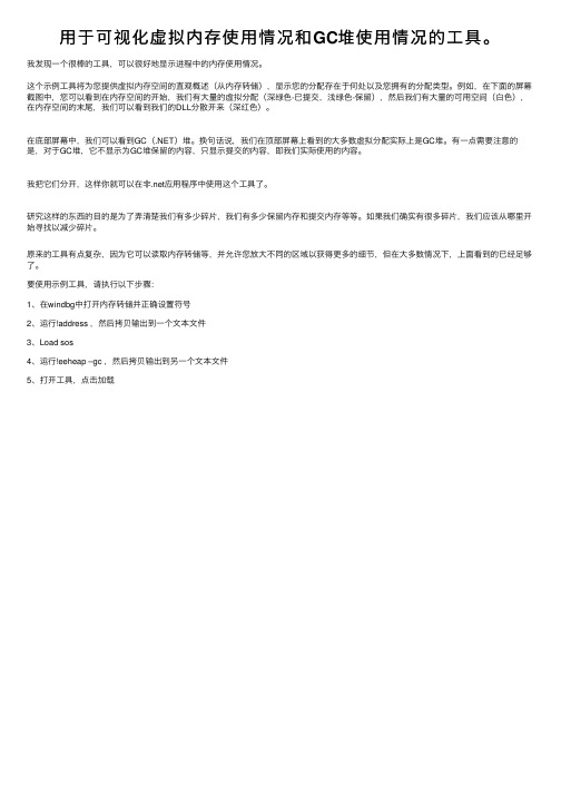
⽤于可视化虚拟内存使⽤情况和GC堆使⽤情况的⼯具。
我发现⼀个很棒的⼯具,可以很好地显⽰进程中的内存使⽤情况。
这个⽰例⼯具将为您提供虚拟内存空间的直观概述(从内存转储),显⽰您的分配存在于何处以及您拥有的分配类型。
例如,在下⾯的屏幕截图中,您可以看到在内存空间的开始,我们有⼤量的虚拟分配(深绿⾊-已提交,浅绿⾊-保留),然后我们有⼤量的可⽤空间(⽩⾊),在内存空间的末尾,我们可以看到我们的DLL分散开来(深红⾊)。
在底部屏幕中,我们可以看到GC(.NET)堆。
换句话说,我们在顶部屏幕上看到的⼤多数虚拟分配实际上是GC堆。
有⼀点需要注意的是,对于GC堆,它不显⽰为GC堆保留的内容,只显⽰提交的内容,即我们实际使⽤的内容。
我把它们分开,这样你就可以在⾮.net应⽤程序中使⽤这个⼯具了。
研究这样的东西的⽬的是为了弄清楚我们有多少碎⽚,我们有多少保留内存和提交内存等等。
如果我们确实有很多碎⽚,我们应该从哪⾥开始寻找以减少碎⽚。
原来的⼯具有点复杂,因为它可以读取内存转储等,并允许您放⼤不同的区域以获得更多的细节,但在⼤多数情况下,上⾯看到的已经⾜够了。
要使⽤⽰例⼯具,请执⾏以下步骤:
1、在windbg中打开内存转储并正确设置符号
2、运⾏!address ,然后拷贝输出到⼀个⽂本⽂件
3、Load sos
4、运⾏!eeheap –gc ,然后拷贝输出到另⼀个⽂本⽂件
5、打开⼯具,点击加载。
DS2208数字扫描器产品参考指南说明书
-05 Rev. A
6/2018
Rev. B Software Updates Added: - New Feedback email address. - Grid Matrix parameters - Febraban parameter - USB HID POS (formerly known as Microsoft UWP USB) - Product ID (PID) Type - Product ID (PID) Value - ECLevel
-06 Rev. A
10/2018 - Added Grid Matrix sample bar code. - Moved 123Scan chapter.
-07 Rev. A
11/2019
Added: - SITA and ARINC parameters. - IBM-485 Specification Version.
No part of this publication may be reproduced or used in any form, or by any electrical or mechanical means, without permission in writing from Zebra. This includes electronic or mechanical means, such as photocopying, recording, or information storage and retrieval systems. The material in this manual is subject to change without notice.
霍尼韦尔气体传感器使用说明书

12CONTENTS1. INTRODUCTION .........................................................22. ASSOCIATED DOCUMENTATION ..............................23. SAFETY .......................................................................3 3.1 Warnings ...........................................................3 3.2 Precautions .......................................................34. OPERATIONS .............................................................4 4.1 Installation ........................................................4 4.2 Calibration .. (5)4.3 Fault finding (8)5. MAINTENANCE ..........................................................9 5.1 Changing the electrochemical cell and internal filter ......................................................9 5.2 Changing the external hydrophobic assembly 10 Appendix A - Specifications ..............................11 Appendix B - Glossary ......................................12 Appendix C - Main features . (13)Appendix D-Spare parts (14)APPENDIX A - SPECIFICATIONSAPPENDIX B - EC DECLARATION APPENDIX C - MAIN FEATURESAPPENDIX D - SPARE PARTSmanufacturer’s trademark & addressCE mark - conforms to all applicable European directivescertification numberexplosion protection mark and equipment group & categoryCertification label3745896104. OPERATIONS5. MAINTENANCE4.3FAULT FINDINGSensor reads non-zero all the time:• Gas could be present, ensure that there is no target gas in the atmosphere. Background or other volatile organic gases, eg. solvents, can interfere with the operation of the sensor.Sensor reads non-zero when no gas is present:• adjust the zero on the control card.Sensor reads low when gas is applied:• adjust the span on the control card.• for oxygen versions, check that the neoprene plug has been removed from under the plastic retainer.Sensor reads high when gas is applied:• adjust the span on the control card.Sensor reads zero when gas is applied:• check the wiring.• check the dust protection cap has been removed.• check that the sensor is not obstructed.• replace the sensor if failure is suspected.• for oxygen versions, check that the neoprene plug has been removed from under the plastic retainer.Cannot adjust span or zero at control card:• refer to the technical handbook.5.1 CHANGING ELECTROCHEMICAL CELL ANDINTERNAL FILTER1. Unscrew and remove the grey plastic retainer (or accessory if fitted) from the sensor.2.Remove the old internal hydrophobic assembly bypushing against the snap fit, through one of the retaining slots, with a small flat bladed screwdriver. The assembly will pop out. Do not attempt to lever the assembly out as this may damage the housing.3. Remove the internal metal gauze insert.4.Open the enclosure by unscrewing the sensor capassembly from the sensor main body, ensuring that the electrochemical cell does not rotate with the cap.5a.ToxicGently pull the old electrochemical cell from the pcb. (Dispose of this in accordance with the local regulations).5b.OxygenFor oxygen Sensepoint, unscrew the old cellconnections. Support the screw pillars during removal and refitting of the oxygen cell screws.6. Remove the new cell from its packaging and remove the shorting link across the base of cell.7a. Plug the new cell into the pcb. (toxic cell)7b. Screw in the new cell via the metal tabs. (oxygen cell)8. Screw the sensor cap assembly back onto the sensor main body.9. Fit the new internal metal gauze assembly.10.Fit the new internal hydrophobic assembly.Note: The sensor should now be calibrated. See Section 4.2ATEX SPECIAL CONDITIONS FOR SAFE USEThe detector head must be protected from impact.The detector head must not be used in atmospheres containing greater than 21% oxygen. The integral supply leads must be mechanically protected and terminated in a terminal or junction facility suitable for the areaclassification if the installation. The terminal box and any shrouding metal work (when used) must be effectively earthed. The detector head is considered to present a potential electrostatic risk and must not be located in high air flows or rubbed. The front cover must not be removed when a dust hazard exists and must be fully tightened when replaced. The detector head is designed to be mounted vertically with the gas sensor facing downwards.4.1 INSTALLATIONThe Unit should be fitted to a junction box certified Ex d or Ex e, and fitted with an approved cable gland and connector block. The sensors should be fitted to a tapped hole within the enclosure and locked in place with a locknut if the parallel thread version is being used. Cabling should be multicore, two wires plus screen, conductor size 2.5mm 2 (14AWG) max. Sensors are supplied pre-calibrated.The apparatus should be installed in a location free from dusts and direct heat sources.For optimum protection against water ingress ensure that the sensor is installed facing downwards.Installation is to be performed by a qualified installation engineer, with the power to the unit disconnected.For oxygen versions, remove the neoprene stopper and snap the RFI screen and internal hydrophobic assembly (supplied separately) into place (page 10).See the technical handbook for details of installation in a duct or in forced air conditions.4. OPERATIONS4. OPERATIONS4. OPERATIONS3.1 WARNINGS•T his apparatus is not suitable for use in oxygenenriched atmospheres (>21%V/V). Oxygen deficient atmospheres (<6%V/V) may suppress the sensor output.• Refer to local or national regulations relative to installation at the site.• The operator should be fully aware of the action to be taken if the gas concentration exceeds an alarm level.• The ECC (electrochemical cell) contains a small quantity of acid.• I nstallation should consider not only the best placingfor gas detection related to potential leak points, gas characteristics and ventilation, but also where the potential of mechanical damage is minimized or avoided.• Only assessed by ATEX for ignition hazards• Electrostatic risk - Do not rub or clean with solvents. Clean with a damp cloth. High velocity airflows and dusty environments can cause hazardous electrostatic charges.3.2 CAUTIONS• Exposures to gas above the design range of thesensor may require the sensor to be re-calibrated.•Do not modify or alter the sensor construction as essential safety requirements may be invalidated.• Install Sensepoint using certified Ex e or Ex d junction box, connectors and glanding.•Sensors should be disposed of in accordance with local disposal regulations. Materials used:Sensor: Fortron® (PPS-polyphenylene sulphide), Cell: PPO (modified polyphenylene oxide).• T his equipment is designed and constructed as toprevent ignition sources arising, even in the event of frequent disturbances or equipment operating faults. The electrical input is protected with a fuse.• Do not access the interior of the Sensepoint gas sensor when hazardous (explosive) gas or dust is present. Ensure o-ring is fitted and body is fully tightened when gas cell is replaced.3. SAFETY4.2 CALIBRATIONSensepoint for toxic gas detection is suppliedpre-calibrated, however, for increased accuracy in specific applications, on-site calibration is recommended.Re-calibration should only be attempted by qualified service personnel. Calibration should only be attempted after the sensor has been installed and powered for a time exceeding the warm up time (Table 1).Gas Range Recommended Warm Application Operating Temp.Test up Time MIN. MAX.Concentration TimeH 2S 0 to 20 ppm 10 ppm 3mins 3 mins -20°C +50°C H 2S 0 to 50 ppm 20 ppm3mins 3 mins -20°C +50°C H 2S 0 to 100 ppm 50 ppm3mins 3 mins -20°C +50°C CO0 to 100 ppm 50 ppm3mins 3 mins -20°C +50°C CO 0 to 200 ppm 100 ppm 3mins 3 mins -20°C +50°C CO 0 to 500 ppm 250 ppm 3mins 3 mins -20°C +50°C Cl 2 0 to 5 ppm 3 ppm 5mins 10 mins -20°C +50°C Cl 2 0 to 15 ppm 10 ppm 5mins 10 mins -20°C +50°C O 20 to 25% v/v19% v/v 5mins 1 mins -15°C +40°C NH 3 0 to 50 ppm 25 ppm3mins 10 mins -20°C +40°C NH 3 0 to 1000 ppm 500 ppm3mins 10 mins -20°C +40°C H 2 0 to 1000 ppm 500 ppm 3mins 3 mins -5°C +40°C H 20 to 10000 ppm 3000 ppm3mins 3 mins -5°C+40°CSO 2 0 to 15 ppm 10 ppm 3mins 5 mins -15°C +40°C SO 2 0 to 50 ppm 20 ppm3mins 5 mins -15°C +40°C NO 0 to 100 ppm 50 ppm12hrs 5 mins -5°C+40°CNO 2 0 to 10 ppm5 ppm1hr5 mins-15°C +40°CTable 1:5. MAINTENANCESCREENSCREENSENSORWiring connections are:-The unit requires a nominal 18 to 30V, 30m current-loop-powered supply.First zero the control system with no gas present on the sensor. If target gas is suspected to be in the vicinity of Sensepoint, flow clean air over the sensor using a flow housing (see below).Fit a flow housing and connect a cylinder of either air, for a zero, or a known concentration of gas (approximately 50% FSD) to the flow housing using nylon or PTFE tubing. Tubing lengths should be kept to a minimum to avoidextending the speed of response. Connect the outlet of the flow housing to a safe exhaust area. Pass the gas through the flow housing at a flow rate of approximately1 l to 1.5 l per minute. Allow the sensor to stabilise. When gassing with air, adjust the control card to indicate zero. For span, the control card should be adjusted to indicate the concentration of the target gas being applied. Remove the flow housing and the gas supply.Note: for oxygen, the span gas is normally air at 20.8%v/vO 2. The control card should be adjusted to indicate this when the sensor is in either clean ambient air, or in a flow of 20.8%v/v O 2 in nitrogen from a cylinder. A zero adjustment is not normally required, however it is recommended that the alarm levels are tested using a cylinder of a lower concentration of oxygen in nitrogen.See Table 1 for details of concentrations and times to be used. If the controller cannot be spanned, consult the technical handbook.For calibration using the Weather Protection in high flow applications refer to the technical handbook.Plastic retainerExternal hydrophobic barrier Main body of sensorOxygen cellInternalhydrophobic assembly Sensor cap Toxicelectrochemical cellRFI screen / metal gauze11. Replace the grey plastic retainer or accessory.12. In the event of an apparatus failure, return unit to Honeywell Analytics Ltd.5.2 CHANGING THE EXTERNAL HYDROPHOBIC BARRIERRemove the plastic retainer (or accessory). Remove the old external hydrophobic barrier and replace with the new one. Replace the plastic retainer.4. OPERATIONS。
Prometheus的指标采集与可视化

Prometheus的指标采集与可视化Prometheus是一款受欢迎的开源监控系统,由SoundCloud开发并在2016年正式成为CNCF项目之一。
它采用的是pull方式,通过客户端向多个目标进行抓取,从而实时地收集并存储整个系统的运行状态数据。
随着现代云原生应用架构的发展,Prometheus 对微服务、容器、Kubernetes等应用场景有着广泛的应用。
Prometheus的工作原理是通过抓取指标来实现系统监控。
指标是可被监控的量的度量单位,例如内存使用情况和其他有用的系统参数。
它们被称为time series(时间序列),是由metric name 和一组key-value pair数据组成的。
Prometheus核心组件prometheus server会定期轮询各个target,然后通过HTTP协议来进行抓取并预处理数据,最终将解析后的数据存储在本地的时间序列数据库中。
由于Prometheus的API丰富,因此在数据被存储后,可以通过许多不同的方式(如PushGateway等)来查询和使用这些数据。
指标采集如何选择指标?在Prometheus中,许多有用的指标可以通过外部插件或Prometheus默认的exporters(如node_exporter、blackbox_exporter等)来取得。
对于不太常见的应用程序和服务,可能需要自己编写exporter以便实现度量数据采集。
exporter可以接收应用程序的度量数据,将其转换为Prometheus的格式,并在HTTP端口上暴露出来。
随着Prometheus生态系统的发展,已经有很多内置的exporter供开发人员和系统管理员使用,如果需要的话可以灵活地配置。
此外,还可以使用PromQL(Prometheus Query Language)来查询数据,PromQL是一种功能强大而易于使用的语言,可以从时间序列数据库中检索各种指标数据。
Nsight Eclipse Plugins Edition DG-06450-001 _v9.1

Getting Started GuideTABLE OF CONTENTS Chapter 1. Introduction (1)1.1. About Nsight Eclipse Plugins Edition (1)Chapter 2. Using Nsight Eclipse Edition (2)2.1. Installing Nsight Eclipse Edition (2)2.1.1. Installing CUDA T oolkit (2)2.1.2. Configure CUDA T oolkit Path (2)2.2. Nsight Eclipse Main Window (4)2.3. Creating a New Project (5)2.4. Importing CUDA Samples (6)2.4.1. cuHook Sample (6)2.5. Configure Build Settings (7)2.6. Debugging CUDA Applications (8)2.7. Remote development of CUDA Applications (10)2.8. Debugging Remote CUDA Applications (12)2.9. Profiling CUDA applications (18)2.10. Importing Nsight Eclipse Projects (19)2.11. More Information (21)LIST OF FIGURESFigure 1 Nsight main window after creating a new project (5)Figure 2 Debugging CUDA application (9)Figure 3 Debugging CUDA application (10)Figure 4 Debugging remote CUDA application (18)Figure 5 Profiling CUDA Application (19)This guide introduces Nsight Eclipse Plugins Edition and provides instructions necessary to start using this tool. Nsight Eclipse is based on Eclipse CDT project. Fora detailed description of Eclipse CDT features consult the integrated help "C/C++ Development User Guide" available from inside Nsight (through Help->Help Contents menu).1.1. About Nsight Eclipse Plugins EditionNVIDIA® Nsight™ Eclipse Edition is a unified CPU plus GPU integrated development environment (IDE) for developing CUDA® applications on Linux and Mac OS X for the x86, POWER and ARM platforms. It is designed to help developers on all stages of the software development process. Nsight Eclipse Plugins can be installed on vanilla Eclipse 4.4 or later using the standard Help->Install New Software.. Menu. The principal features are as follows:‣Edit, build, debug and profile CUDA-C applications‣CUDA aware source code editor – syntax highlighting, code completion and inline help‣Graphical user interface for debugging heterogeneous applications‣Profiler integration – Launch visual profiler as an external application with the CUDA application built in this IDE to easily identify performance bottlenecksFor more information about Eclipse Platform, visit 2.1. Installing Nsight Eclipse EditionNsight Eclipse Plugins archive is part of the CUDA Toolkit. Nsight Eclipse Plugins archive can be installed using the Help -> Install New Software... Menu on Eclipse 4.4 or later2.1.1. Installing CUDA T oolkitTo install CUDA Toolkit:1.Visit the NVIDIA CUDA Zone download page:/object/cuda_get.html2.Select appropriate operating system. Nsight Eclipse Edition is available in Mac OS X and Linux toolkit packages.3.Download and install the CUDA Driver.4.Download and install the CUDA Toolkit.5.Follow instructions to configure CUDA Driver and Toolkit on your system.2.1.2. Configure CUDA T oolkit PathTo get started, CUDA Toolkit path must be configured in Eclipse with Nsight Plugins:1.Open the Preferences page, Window > Preferences.2.Go to CUDA toolkit section.3.Select the CUDA toolkit path to be used by Nsight. CUDA tookits that are installed in the default location will automatically appear.4.CUDA toolkit path can be also specified in the project properties page in order to use different toolkit for a project.5.For QNX: When QNX is selected as Target OS, a dialog will be displayed to set theQNX_HOST and QNX_TARGET environment variables if they were not already set.QNX_HOST environment variable identifies the directory that holds the host-related components:QNX_TARGET environment variable identifies the directory that holds the target-related components:2.2. Nsight Eclipse Main WindowOn the first run Eclipse will ask to pick a workspace location. The workspace is a folder where Nsight will store its settings, local files history and caches. An empty folder should be selected to avoid overwriting existing files.The main Nsight window will open after the workspace location is selected. The main window is divided into the following areas:‣Editor - displays source files that are opened for editing.‣Project Explorer - displays project files‣Outline - displays structure of the source file in the current editor.‣Problems - displays errors and warnings detected by static code analysis in IDE or bya compiler during the build.‣Console - displays make output during the build or output from the running application.2.3. Creating a New Project1.From the main menu, open the new project wizard - File > New... > C/C++ Project2.Specify the project name and project files location.3.Specify the project type like executable project.4.Specify the CUDA toolchain from the list of toolchains.5.Specify the project configurations on the next wizard page.plete the wizard.The project will be shown in the Project Explorer view and source editor will be opened.7.Build the project by clicking on the hammer button on the main toolbar.Figure 1 Nsight main window after creating a new project2.4. Importing CUDA SamplesThe CUDA samples are an optional component of the CUDA Toolkit installation. Nsight provides a mechanism to import these samples and work with them easily: Samples that use the CUDA driver API (suffixed with "Drv") are not supported byNsight.1.From the main menu, open the new project wizard - File > New... > C/C++ Project2.Specify the project name and project files location.3.Select Import CUDA Sample under Executable in the Project type tree.4.Select CUDA toolchain from the Toolchains option. location.5.On the next wizard page select project sample you want to import. Also select the target CPU architecture. Press Next...6.Specify the project parameters on the next wizard page.plete the wizard.The project will be shown in the Project Explorer view and source editor will be opened.8.Build the project by clicking on the hammer button on the main toolbar.2.4.1. cuHook SamplecuHook sample builds both the library and the executable. cuHook sample should be imported as the "makefile" project using the following steps.1.From the main menu, open the new project wizard - File > New... > C/C++ Project2.Select project type "Makefile project" and choose "Empty Project"3.Specify the project name and project files location.plete the wizard.The project will be shown in the Project Explorer view.5.Right click on the project - Import... > General > File System6.On the next wizard page, select the location of cuHooksample(Samples/7_CUDALibraries/cuHook)7.Select all the source files and makefile and Finish the wizard8.Build the project by clicking on the hammer button on the main toolbar.9.To run the sample, from the main menu - Run > Run Configurations... > Select the executable > Go to Environment tab > New... > enter Name=LD_PRELOAD, Value=./ libcuhook.so.1 > Run will execute the sample2.5. Configure Build SettingsTo define build settings: In the C/C++ Projects view, right-click your project, and select Properties. Select C/C++ Build, Settings from the list.The following are the categories of Nvcc linker settings that can be configured for the selected project.All options field in the main page is not editable and it's the collection of options setin the child categories.‣Libraries - Configure library search path(-L) and to include linker libraries(-l). When you are cross compiling for different target os, the library search path should point to the appropriate location where the target os libraries are present.‣Miscellaneous - Set additional linker options and option to link with OpenGL libraries.‣Shared Library Settings - Set option to build a shared library.The following are the categories of Nvcc Compiler settings that can be configured for the selected project.All options field in the main page is not editable and it's the collection of options set‣Dialect - Select the language standard and dialect options.‣Preprocessor - Add the defined and undefined symbols for the preprocessor.‣Includes - Set include paths and include files for the compiler.‣Optimization - Set the compiler optimization level.‣Debugging - Set the options to generate debug information.‣Warnings - Set inhibit all warning messages.‣CUDA - Generate code for different real architectures with the PTX for the same vitrual architectures.2.6. Debugging CUDA ApplicationsNsight must be running and at least one project must exist.1.In the Project Explorer view, select project you want to debug. Make sure the project executable is compiled and no error markers are shown on the project.2.Right click on the project and go to Debug As > NVIDIA CUDA GDB Debugger menu.3.You will be offered to switch perspective when you run debugger for the first time. Click "Yes".Perspective is a window layout preset specifically designed for a particular task.4.Application will suspend in the main function. At this point there is no GPU code running.5.Add a breakpoint in the device code. Resume the application.Debugger will break when application reaches the breakpoint. You can now explore your CUDA device state, step through your GPU code or resume the application.Figure 2 Debugging CUDA applicationAdditional debugger options can be set in the debug configuration dialog through Run > Debug Configurations .. menu..Figure 3 Debugging CUDA application2.7. Remote development of CUDA ApplicationsNsight Eclipse Edition also supports remote development of CUDA application starting with CUDA Toolkit 6.0. The picture below shows how Nsight Eclipse Edition can beused for local as well as remote development:For remote development you do not need any NVIDIA GPU on your host system. The remote target system can be a Linux x86 or POWER system with an NVIDIA GPU or an Tegra-based ARM system. Nsight IDE and UI tools can only be hosted on x86 and POWER systems.Nsight Eclipse Plugins supports the cross compilation mode for remote devices.In the cross compilation mode the project resides on the host system and the cross compilation is also done on the host system. The cross compilation mode is only supported on an Ubuntu x86 host system.To cross compile select the target cross compile architecture in CPU architecture dropdown in the project properties page:2.8. Debugging Remote CUDA Applications Remote debugging is available starting with CUDA Toolkit 5.5. A dedicated GPU is not required to use Nsight remote debugging UI. A dedicated GPU is still required on the debug target. Only Linux targets are supported. Debug host and target may run different operating systems or have different CPU architectures. The remote machine must be accessible via SSH and CUDA Toolkit must be installed on both machines.If there is a firewall between the host and the target, it must be set up to let RSP1.Select the project and right click then go to Debug As...>NVIDIA CUDA GDBDebugger(Remote) menu item.2.Type the full path to a local executable or select one using the Local file... button.3.Select a remote connection from a drop-down list or press the Add connection... button to create a new one.4.If you are creating a new remote connection, select the SSH Only connection type, press Next, and type the host name(or IP address) as well as the connection name anddescription (both are optional) and then press Finish.5.For Android devices: To configure the remote connection using Android debug bridge, select the Android debug bridge from the Remote Connection drop-downlist, Android device must be connected to the host system using USB port.Press Manage button, and enter or select the path to adb utility. You need to install Android SDK platform tools to use Android debug bridge. press Detect button tofind the android device available through ADB.6.Optional: Press Connect to verify the selected remote connection.7.Press the Next button.8.Type the full path to cuda-gdbserver on the remote system or select one using theBrowse... button.9.Click on "Add new path" or on the Browse... button to specify the path to the shared libraries the remote application depends on.10.C lick on the Finish button to finish the new debug configuration wizard and start debugging the application.11.Y ou will be offered to switch perspective when you run the debugger for the first time. Click Yes.Perspective is a window layout preset specifically designed for a particular task. The debugger will stop at the application main routine. You can now set breakpoints, orresume the application.Figure 4 Debugging remote CUDA application2.9. Profiling CUDA applicationsNsight must be running and at least one project must exist. Profiler cannot be used when debugging session is in progress.Nsight Eclipse Edition profiling features are based on the NVIDIA Visual Profiler ( nvvp ) code. Nsight Eclipse Plugins Edition will launch the Visual Profiler as an external tool with the executable and other information from the selected project.1.In the Project Explorer view, select project you want to profile. Make sure the project executable is compiled and no error markers are shown on the project.2.Select the project and right click and go to Profile As>NVIDIA Visual Profiler menu.Nsight Eclipse will launch the Visual Profiler to specify extra profiler options with the executable information already passed from the selected project.Figure 5 Profiling CUDA Application2.10. Importing Nsight Eclipse ProjectsThe projects that are created with Nsight Eclipse Edition can be imported into the Eclipse workbench with Nsight Eclipse plugins.1.Open Nsight Eclipse edition and select the project that needs to be exported.2.Right click on the Nsight Eclipse project and go to - Export > C/C++ > C/C++ Project Settings > Next menu.3.Select the project and settings to export.4.Specify the "Export to file" location.5.Settings will be stored in the given XML file.6.Go to Eclipse workbench where the project settings needs to be imported.7.Create a C/C++ Project from the main menu File > New > C/C++ Project8.Specify the project name and choose Empty project type with CUDA toolchains.9.Right click on the project to import the source files. Import > General > File System >(From directory) or copy the source files from the existing project.10.I mport the project settings like include paths and symbols using the following right click menu Import > C/C++ > C/C++ Project Settings >Next...11.S elect the location of the project settigns file and select the project and configurationon the next wizard page.12.C omplete the wizard.The project settings will be imported from the file exported from Nsight Eclipse Edition.13.B uild the project by clicking on the hammer button on the main toolbar.2.11. More InformationMore information about the Eclipse CDT features and other topics is available in the Help contents. To access Help contents select Help->Help Contents from the Nsight main menu.More information about CUDA, CUDA Toolkit and other tools is available on CUDAweb page at /cudaNoticeALL NVIDIA DESIGN SPECIFICATIONS, REFERENCE BOARDS, FILES, DRAWINGS, DIAGNOSTICS, LISTS, AND OTHER DOCUMENTS (TOGETHER AND SEPARATEL Y, "MATERIALS") ARE BEING PROVIDED "AS IS." NVIDIA MAKES NO WARRANTIES, EXPRESSED, IMPLIED, STATUTORY, OR OTHERWISE WITH RESPECT TO THE MATERIALS, AND EXPRESSL Y DISCLAIMS ALL IMPLIED WARRANTIES OF NONINFRINGEMENT, MERCHANTABILITY, AND FITNESS FOR A PARTICULAR PURPOSE.Information furnished is believed to be accurate and reliable. However, NVIDIA Corporation assumes no responsibility for the consequences of use of such information or for any infringement of patents or other rights of third parties that may result from its use. No license is granted by implication of otherwise under any patent rights of NVIDIA Corporation. Specifications mentioned in this publication are subject to change without notice. This publication supersedes and replaces all other information previously supplied. NVIDIA Corporation products are not authorized as critical components in life support devices or systems without express written approval of NVIDIA Corporation.TrademarksNVIDIA and the NVIDIA logo are trademarks or registered trademarks of NVIDIA Corporation in the U.S. and other countries. Other company and product names may be trademarks of the respective companies with which they are associated. Copyright© 2007-2018 NVIDIA Corporation. All rights reserved.。
prom 指标 -回复
prom 指标-回复标题:深入理解Prometheus指标:一种系统监控的强大工具Prometheus,作为一个开源的系统监控和报警工具,已经在众多企业和组织中得到了广泛应用。
其核心特性之一就是其强大的指标系统,使得用户能够对系统的各种状态和行为进行精细的监控和分析。
本文将详细解析Prometheus的指标系统,帮助读者更好地理解和使用这一工具。
一、Prometheus指标的基本概念在Prometheus中,指标(Metric)是系统状态的基本单位。
每个指标都由一个名字和一系列的标签(Label)组成,用于描述特定的测量值。
这些测量值可以是任何可以被量化的事物,如CPU利用率、网络带宽、数据库查询次数等。
二、Prometheus指标的类型Prometheus支持四种主要的指标类型:1. Counter:计数器,表示只增不减的数值,通常用于记录事件的数量,如请求总数、错误总数等。
2. Gauge:仪表盘,表示任意的数值,可以增加也可以减少,通常用于表示瞬时状态,如CPU利用率、内存使用量等。
3. Histogram:直方图,用于记录数据分布的情况,如请求响应时间的分布。
4. Summary:摘要,类似于直方图,但提供更灵活的计算方式,如百分位数。
三、Prometheus指标的命名和标签在Prometheus中,每个指标都有一个唯一的名称,并且可以附带一组标签。
这些标签用于区分同一类型的指标在不同环境或条件下的表现。
例如,一个名为"http_requests_total"的Counter指标,可以带有以下标签:"method"(HTTP方法)、"handler"(处理程序)、"status_code"(HTTP状态码)。
这样,我们就可以分别统计GET、POST等不同HTTP 方法的请求总数,或者200、404等不同状态码的请求总数。
IBM Cognos Transformer V11.0 用户指南说明书
r performance包依赖关系

r performance包依赖关系
r performance包的依赖关系如下:
- Rcpp:一个R的包装器,用于访问C++代码的功能。
- gridExtra:提供了在网格上排列多个图形的能力。
- ggplot2:用于创建漂亮且高度可定制的图形的包。
- dplyr:用于数据转换和操作的包。
- stringr:提供了一组用于对字符串进行操作的工具函数。
- lazyeval:用于延迟计算的包。
- methods:用于定义和操作S3和S4类的方法。
- stats:包含R中常用的统计方法和函数的包。
- graphics:包含用于绘图的基本函数的包。
- grDevices:提供了R图形设备系统的接口。
- utils:提供了一些实用功能的包。
- datasets:提供了一些常用的示例数据集的包。
- methods:用于定义和操作S3和S4类的方法。
请注意,R包的依赖关系可能会根据版本的更新而有所变化。
建设工程造价咨询规范

表 A.0.1 投资估算封面 .............................................................................................. 50 表 A.0.2 投资估算签署页 .......................................................................................... 51 表 A.0.3 投资估算编制说明 ...................................................................................... 52 表 A.0.4 投资估算汇总表 .......................................................................................... 53 表 A.0.5 单项工程投资估算汇总表 .......................................................................... 55 附录 B 设计概算成果文件格式..................................................................................... 56 表 B.0.1 设计概算封面 .............................................................................................. 56 表 B.0.2 设计概算签署页 ...................................
- 1、下载文档前请自行甄别文档内容的完整性,平台不提供额外的编辑、内容补充、找答案等附加服务。
- 2、"仅部分预览"的文档,不可在线预览部分如存在完整性等问题,可反馈申请退款(可完整预览的文档不适用该条件!)。
- 3、如文档侵犯您的权益,请联系客服反馈,我们会尽快为您处理(人工客服工作时间:9:00-18:30)。
ABS/BPPP Guide to Initial Pilot Checkout:Using Beech Performance ChartsBeech Pilot’s Operating Handbook (POH) performance charts appear complex, but they are actually easy to use. The trick is to look at each chart in segments, using one segment at a time as your performance calculation progresses.Most Beech performance charts contain three types of data, as indicated on this sample:Associated ConditionsThe first type of data is the associated conditions. This is the piloting technique required in order to obtain the computed aircraft performance—do things differently and you don’t know what performance will result. In the example of the Takeoff Distance chart the associated conditions call for pull power before brake release, flaps up and landing gear retracted as soon as the airplane achieves a positive rate of climb. The power technique suggests this is essentially a short-field takeoff technique; a rolling takeoff will result in a longer takeoff roll, but the chart does not indicate how much longer. Not mentioned in the associated conditions but assumed by the manufacturer is that the runway surface is paved, level and dry. Any other runway condition will affect takeoff performance, but we have no guidance as to how much.Look closely at the associated conditions for each performance chart. Pilots must apply a generous safety margin to all performance calculations based on experience in the specificairplane under similar conditions.ABS/BPPP Guide to Initial Pilot Checkout Appendix: Using Performance ChartsABS/BPPP Guide to Initial Pilot Checkout Appendix: Using Performance ChartsAirspeedsThe second type of data are target airspeeds. Each performance chart will stipulate airspeeds required to obtain computed performance; the speeds may differ based on airplane weight and/or configuration.Any deviation from either the recommended airspeeds and/or the associated conditionstechnique requires the pilot use his/her own judgment based on experience. Do not assume the airplane will perform as computed if you use any other technique or speed.Performance CalculationThe actual performance calculation is also easy if you approach it in segments. Most Beech performance charts are divided into multiple sections, boarded by reference lines. Use one section at a time as you compute airplane performance. For example:1. Density altitude. In the first section compare ambient air temperature to the airplane’spressure altitude. If a data line curves, interpolate between the lines as needed. For example:OAT = 22°C and pressure altitude is 3000 feet. Fin d the intersection of these data lines and move perpendicularly from that point to the next reference line, as below:2. Aircraft weight. In the second section you’ll adjust the calculation for the airplane’sweight. From the point on the reference line you found in the first section, follow theslope of the lines in the second section downward until you intersect the airplane’sweight. From that intersection, move horizontally to the next reference line, as shown below with a sample 3150-pound airplane weight:3. Headwind/Tailwind: The third section of the Takeoff Distance chart permits you toaccount for the effect of headwind or tailwind on performance. From the secondreference line follow the slope of the lines in this section downward to intersect acomputed headwind component, or upward to intersect a computed tailwind component on takeoff.Note the maximum tailwind component for which data are available is 10 knots. From that point of intersection move horizontally to the next reference line. In the examplebelow there is a 12-knot headwind component:ABS/BPPP Guide to Initial Pilot Checkout Appendix: Using Performance Charts4. Obstacle clearance. The final section of the chart lets you compute final performance.In our example of the Takeoff Distance chart it actually provides two results: ground roll distance from brake release to liftoff, and obstacle clearance distance from brakerelease to a point where the airplane is 50 foot above the elevation of the beginning of its takeoff roll. Notice the chart is not applicable to intermediate obstacle heights, e.g., itdoes not accurately predict the distance needed to clear a 30-foot obstacle.To calculate performance in our example:•From the last reference point move horizontally to the far right to determine takeoff roll distance.•From that same reference point follow the slope of the lines upward to the farright to determine the 50-foot obstacle clearance distance.ABS/BPPP Guide to Initial Pilot Checkout Appendix: Using Performance ChartsMost Beechcraft performance charts use this basic layout and require the same technique, although not all charts contain as many variables or require as much interpretation. A little practice with each chart creates the competence necessary to compute expected aircraft performance using the associated conditions and recommended performance speeds.Performance Calculations Adjustments (certain IO-550 A36s, G36s)Pilot’s Operating Handbooks for the IO-550 A36 and the G36 contain a two-page introduction to the Performance section that in some cases dramatically alters the results of performance calculations made using the charts in that POH section. The adjustments apply to IO-550 engines delivered or subsequently retrofitted with non-altitude compensating fuel pumps (i.e., they employ the engine-driven fuel pump that requires the pilot to manually lean for takeoff above sea level). As the pages (below) show, correction values are small unless the ambient air temperature is above standard, in which case the effect on calculated performance is dramatic. ABS has repeatedly asked Hawker Beechcraft and its predecessor companies to explain the reasoning behind these correction values, when the engine, if properly leaned, should develop the same power with or without the altitude compensating fuel pump, and the performance charts themselves account for higher-than-standard temperatures. To date Beech technical support has been unable to answer the question, and our queries to Engineering andFlight Test have gone repeatedly unanswered.ABS/BPPP Guide to Initial Pilot Checkout Appendix: Using Performance ChartsABS/BPPP Guide to Initial Pilot Checkout Appendix: Using Performance ChartsCruise PerformanceBeech’s Cruise Performance charts are an exception. Beech provides recommended power settings based either on a computed percentage of power or merely recommendedcombinations of manifold pressure and propeller rpm, depending on the POH applicable to the specific airplane serial number. In the case of the IO-550-equipped A36 and Baron, beginning in 1984, Beech provides two cruise performance charts at recommended MP/RPMcombinations, one with mixture leaned to 20°C rich of peak EGT, the other at 20°C lean of peak EGT. With these exceptions all Beech POH cruise performance, endurance and range tables assume the mixture is leaned to 25°F rich of peak E GT. Any other leaning technique will result in performance differing from that computed using the charts.Each recommended power setting chart contains three blocks of data. In the center you’ll find performance expectations at standard temperature. To the left (or in some POHs, above) the standard conditions table you’ll find colder-than-standard conditions data, for 36°F/20°C below standard temperature. To the right (or below) stand conditions information you’ll see hotter-than-standards data, for 36°F/20°C above standard t emperature. The charts assume a given airplane weight, stated in the chart’s header; different weights will result in different performance. Areas on the chart shaded in grey are those where full-throttle operation will not deliver the percentage of power or manifold pressure recommended for that specific performance chart. In that region the actual manifold pressure created at full throttle is approximate.Use forecasts or actual observed temperatures to determine which section of the chart to use. Interpolate between sections if the temperature is between the listed ranges. Then select your altitude and read performance, or select your desired performance and read altitude. Remember that your actual cruise performance varies with airplane weight, rig, engine condition and leaning technique. Use the POH cruise charts, employing a healthy margin for safety, until you have enough experience in the specific airplane to better judge actual cruise performance.Other chartsOther performance charts in the POH are used in the same way, by matching various airplaneand environmental factors and reading or interpolating the results.ABS/BPPP Guide to Initial Pilot Checkout Appendix: Using Performance Charts。
