W7 Exposition (1) definition
Windows 7系统各服务项介绍
Windows 7系统各服务项介绍Adaptive brightness监视周围的光线状况来调节屏幕明暗,如果该服务被禁用,屏幕亮度将不会自动适应周围光线状况。
该服务的默认运行方式是手动,如果你没有使用触摸屏一类的智能调节屏幕亮度的设备,该功能就可以放心禁用。
Application Layer Gateway ServiceWindows XP/Vista中也有该服务,作用也差不多,是系统自带防火墙和开启ICS共享上网的依赖服务,如果装有第三方防火墙且不需要用ICS方式共享上网,完全可以禁用掉。
Application Management该服务默认的运行方式为手动,该功能主要适用于大型企业环境下的集中管理,因此家庭用户可以放心禁用该服务。
Background Intelligent Transfer Service在后台传输客户端和服务器之间的数据。
如果禁用了BITS,一些功能,如Windows Update,就无法正常运行。
该服务的默认运行方式是自动,这个服务的主要用途还是用于进行Windows Update或者自动更新,最好不要更改这个服务。
Base Filtering Engine同样为系统防火墙,VPN以及IPsec提供依赖服务,同时也是系统安全方面的服务,如果使用第三方VPN拨号软件并且不用系统的防火墙以及ICS共享上网,为了系统资源,关闭它吧,否则就别动它。
BitLocker Drive Encryption Service向用户接口提供BitLocker客户端服务并且自动对数据卷解锁。
该服务的默认运行方式是手动,如果你没有使用BitLocker设备,该功能就可以放心禁用。
Block Level Backup Engine Service估计是和备份恢复方面用的服务,无任何依赖关系,默认是手动,也从来没有看他启动过。
就放那吧,不用管了。
Bluetooth Support Service如果你没有使用蓝牙设备,该功能就可以放心禁用。
7_Series_Schematic_Review_Recommendations_xart_040714
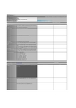
Item VCCINT VCCBRAM VCCAUX VCCAUX_IO_G# VCCO Bank 0
Xilinx Recommendation 1.0V, 0 of 680 uF, 1 of 330 uF, 0 of 100 uF,0 of 47 uF, 4 of 4.7 uF, 6 of 0.47 uF 1.0V, 1 of 100 uF, 0 of 47 uF, 0 of 4.7 uF , 2 of 0.47 uF 1.8V, 1 of 47 uF, 2 of 4.7 uF, 4 of 0.47 uF Does not apply to selected family or device. 1.5V - 3.3V, 1 of 47uF
FCS_B
Connect FCS_B to the SPI flash chip-select input pin and connect FCS_B to an external 4.7 KΩ (or stronger) pull-up to VCCO_14.
TDO
For an isolated device or for the last device in a JTAG chain, connect TDO to the JTAG cable header's TDO input signal. Otherwise, when the FPGA is not the last device in a JTAG chain, connect to the TDI pin of the downstream JTAG device in the JTAG scan chain. For the Xilinx 14-pin JTAG ribbon cable header, TDO is pin 8.
windows7下提示is_not

windows7下提⽰is_notVS2008 在 W INDOWS7 B ETA7000下编译出错-T HE BINARY IS NOT A VALID W INDOWS IMAGE.更新:新装的7048 X64没出现这个问题了,原因还不知道前些天装上了W INDOWS7B ETA7000X86,却发现原先的项⽬编译会出现链接错误:MT.EXE : GENERAL ERROR C101008D:F AILED TO WRITE THE UPDATED MANIFEST TO THE RESOURCE OF FILE "R ELEASE\T EST.EXE".T HE BINARY IS NOT A VALID W INDOWS IMAGE.是MT.EXE在嵌⼊MANIFEST⽂件的时候遇到错误,从⽹上找到的解决⽅案,是在链接器设置选项中,启⽤R ANDOMIZED B ASE A DDRESS ,如下图:原因:JOHN ROBBINS' BLOGS ATURDAY,J ANUARY 24,20095:48PM JROBBINST HE C ASE OF THE C ORRUPT PE B INARIESA FTER INSTALLING W INDOWS 7,I ALSO INSTALLED THE W INDOWS 7 SDK AS I WANTED TO POKE AROUND THE UPDATED HEADERS AND DOCUMENTATION FILES TO SEE WHAT WAS NEW AT A LOW LEVEL.A DDITIONALLY,I WANTED TO MAKE SURE ALL MY CODE COMPILED AGAINST THE NEW HEADERS AND LIBRARIES IN CASE SOMEONE TAKING MY NATIVE DEBUGGING CLASS TRIED IT AND RAN INTO PROBLEMS.A FTER MANY YEARS OF THE SDK TEAM COMPLETELY IGNORING V ISUAL S TUDIO, THE W INDOWS 7SDK INSTALLATION NOW LOOKS FOR V ISUAL S TUDIO AND PROPERLY INTEGRATES WITH IT (I BELIEVE THIS STARTED WITH THE V ISTA SDK).A FTER HUNDREDS OF THOUSANDS OF EMAILS OVER THE YEARS FROM PEOPLE WHO COULDN'T COMPILE CODE FROM MY BOOKS AND COLUMNS BECAUSE THEY HADN'T GONE THROUGH THE MANUAL GYRATIONS TO INTEGRATE THE LATEST SDK WITH THE DEVELOPMENT ENVIRONMENT, IT'S A HUGE HELP.A S I HAVE ALL MY BUILDS AUTOMATED,I LET RIP AND GOT A BUILD FAILURE ON A FEW RELEASE BUILDX86AND X64BINARIES.T HE FAILURE WAS LIKE THE FOLLOWING IN ALL THOSE CASES:MT.EXE : GENERAL ERROR C101008D:F AILED TO WRITE THE UPDATED MANIFEST TO THE RESOURCE OF FILE "..\..\..\..\R ELEASE\FTS IMP T EST.EXE".T HE BINARY IS NOT A VALID W INDOWS IMAGE.MT.EXE IS THE TOOL USED TO EMBED THE MANIFEST INTO YOUR BINARIES.A S I WAS RUNNING A BETA OS,I WONDERED IF THIS WAS A PROBLEM WITH ANTI-VIRUS,SO I DISABLED E T RUST AND TRIED THE BUILD AGAIN BUT STILL GOT THE SAME ERROR.A S I'M USING V ISUAL S TUDIO 2008SP1,CL.EXE AND LINK.EXE ARE DOING ALL THE MAIN WORK OF COMPILING, BUT MT.EXE COMES FROM THE SDK.S INCE THIS CODE COMPILED CORRECTLY ON MY V ISTA COMPUTER WITH THE V ISTA SDK INSTALLED,MY NEXT STEP WAS TO SEE IF THIS WAS POSSIBLY A PROBLEM WITH MT.EXE OR IF CL.EXE AND LINK.EXE WERE EXPOSING A BUG IN THE OPERATING SYSTEM DLL S THEY WERE USING.I UNINSTALLED THE W INDOWS 7 SDK,WHICH REVERTED V ISUAL S TUDIO 2008SP1TO USING THE V ISTA SDK.G IVING THE RECOMPILES A GO,I GOT THE SAME ERROR FROM MT.EXE.I VERIFIED THAT I WAS IN FACT USING THE MT.EXE FROM THE V ISTA SDK.O NE THING THAT WAS CONFUSING TO ME WAS THAT MT.EXE FROM THE VISTA SDK AND W INDOWS 7SDK BOTH REPORT THE SAME VERSION NUMBER,BUT THE BINARIES ARE DIFFERENT SIZES.L OOKING CLOSER AT WHAT BINARIES WERE GETTING CORRUPT,IT WAS ONLY FOUR OUT OF 56.EXE FILES IN MY BUILD.I NTERESTINGLY, THEY WERE ALL CONSOLE APPLICATIONS THAT WERE UNIT TESTS.F IRING UP V ISUAL S TUDIO,I CREATED THE CANONICAL TEST CONSOLE APPLICATION,H ELLO W ORLD,AND VERIFIED THAT IT COMPILED.L OOKING AT THE BUILD.HTM FILE,I SAW THAT H ELLO W ORLD HAD THE FOLLOWING IN IT:C REATING COMMAND LINE "MT.EXE @C:\J UNK\CRUFT\H ELLO W ORLD\R ELEASE\RSP00000840485968.RS P /NOLOGO"C REATING TEMPORARY FILE "C:\J UNK\CRUFT\H ELLO W ORLD\R ELEASE\BAT00000940485968.BAT " WITH CONTENTS[@ECHO M ANIFEST RESOURCE LAST UPDATED AT %TIME% ON %DATE%>.\R ELEASE\MT.DEP]F OR TWO SECONDS,I WAS A LITTLE CONFUSED ABOUT THE TEMPORARY FILE CREATION BECAUSE MY FAILING BUILDS DIDN'T HAVE THAT.W HAT THE OUTPUT TOLD ME WAS THAT THE TEMPORARY FILE INDICATING MT.EXE CREATES THE RESOURCE UPDATE TIME FILE AFTER IT RUNS SUCCESSFULLY.M Y HYPOTHESIS AT THIS POINT WAS THAT EITHER LINK.EXE WAS CREATING A CORRUPT BINARY BEFORE MT.EXE WORKED ON IT, OR IT WAS MT.EXE CORRUPTING THE BINARY ITSELF.U SING ONE OF MY PROJECTS THAT PRODUCED A CORRUPT BINARY,I COPIED OUT THE COMMAND LINES FOR CL.EXE,LINK.EXE, AND MT.EXE FROM ITS BUILD.HTM AND RAN THEM DIRECTLY FROM A BATCH FILE AT THE COMMAND LINE (PROPERLY SET UP WITH VCVARS.BAT).I WANTED TO LOOK AT WHAT WAS IN THE P ORTABLE E XECUTABLE (PE) DATA TO SEE IF ANYTHING WAS AMISS.B Y THE WAY, YOU NEED TO READ M ATT P IETREK'S DEFINITIVE "A N I N-D EPTH L OOK INTO THE W IN32 P ORTABLE E XECUTABLE F ILE F ORMAT" P ARTS 1 AND P ART 2 YOU'LL LEARN A TON ABOUT HOW W INDOWS WORKS.R UNNING DUMPBIN.EXE/HEADERS ON THE RESULTING EXE ALLOWED ME TO LOOK AT THE MAIN PORTIONS.B ECAUSE MT.EXE PUTS THE MANIFEST INTO THE RESOURCE SECTION OF THE BINARY,I PAID SPECIAL ATTENTION TO IT:SECTION HEADER#4.RSRC NAME0 VIRTUAL SIZE4000 VIRTUAL ADDRESS (00404000 TO 00403FFF)0 SIZE OF RAW DATA0 FILE POINTER TO RAW DATA0 FILE POINTER TO RELOCATION TABLE0 FILE POINTER TO LINE NUMBERS0 NUMBER OF RELOCATIONS0 NUMBER OF LINE NUMBERS40000040 FLAGSI NITIALIZED D ATAR EAD O NLYD O YOU SEE THE PROBLEM?H ERE'S A GOOD RESOURCE SECTION FOR COMPARISON:SECTION HEADER#4.RSRC NAME2B0 VIRTUAL SIZE4000 VIRTUAL ADDRESS (00404000 TO 004042AF)400 SIZE OF RAW DATA1800 FILE POINTER TO RAW DATA (00001800 TO 00001BFF)0 FILE POINTER TO RELOCATION TABLE0 FILE POINTER TO LINE NUMBERS0 NUMBER OF RELOCATIONS0 NUMBER OF LINE NUMBERS40000040 FLAGSI NITIALIZED D ATAR EAD O NLYI NTERESTING!T HERE'S A RESOURCE SECTION,BUT IT IS OBVIOUSLY CORRUPT BECAUSE SOMETHING NOT FILLING OUT THE RAW DATA INFORMATION.A S THE MANIFEST GOES IN THE RESOURCE SECTION,MT.EXE REALLY CAN'T ADD TO A SECTION WHOSE RAW DATA STARTS AT ZERO.S INCE THE APP WIZARD GENERATED PROJECT IS NOT PRODUCING CORRUPT BINARIES BUT I HAVE SEVERAL PROJECTS THAT ARE,IT'S TIME TO LOOK AT THE LINK.EXE AND MT.EXE SWITCHES TO SEE WHAT MY PROJECTS HAVE SET THAT ARE TRIPPING EITHER OF THOSE TOOLS UP.T HE EASY WAY FOR ME TO DO THAT IS LOOK AT THE .VCPROJ FILES IN THE FANTASTIC,AND FREE, S OURCE G EAR D IFF M ERGE.(I CAN'T RAVE ENOUGH ABOUT D IFF M ERGE!)D IFF M ERGE POINTED ME WRITE TO THE .VCPROJ,VCL INKER T OOL R ANDOMIZED B ASE A DDRESS ATTRIBUTE AS THE ONLY REAL DIFFERENCE BETWEEN THE FILES.I N THE APP WIZARD PROJECT, THE VALUE IS 1,FOR MY BAD PROJECT,THE VALUE IS 2.A CHECK IN THE PROJECT PROPERTIES SHOWS A VALUE OF 2MAPS TO THE LINKER SWITCH /DYNAMICBASE:NO.I N MY BAD PROJECT,I CHANGE THE VALUE TO/DYNAMICBASE AND THE PREVIOUSLY CORRUPT RELEASE BUILD BUILT AND WORKED PERFECTLY.O NCE I FIX ALL MY BROKEN PROJECTS TO USE /DYNAMICBASE INSTEAD OF /DYNAMICBASE:NO,ALL MY BUILD PROBLEMS GO AWAY.A S I MENTIONED EARLIER, THE CORRUPT BUILDS HAPPENED TO BE SEVERAL OF MY UNIT TESTS,WHICH IS WHERE YOU MIGHT SEE ITAS WELL.T HE EXACT SITUATION I WAS GETTING THE CORRUPT BINARY IS AS FOLLOWS:O N W INDOWS 7 WITH V ISUAL S TUDIO 2008SP1T HERE'S NO RESOURCE FILE IN THE BINARY.I T'S A RELEASE BUILDY OU ARE SPECIFICALLY NOT SETTING /DYNAMICBASE TO THE LINKERA FTER I SPENT THE 20MINUTES TRACKING THIS PROBLEM DOWN,I THOUGHT MAYBE I SHOULD READ THE WINDOWS 7SDK R EAD M E FILE TO SEE IF THIS WAS A KNOWN ISSUE.S ECTION 5.3.6,TITLED "P ROBLEM R UNNING MT.EXE ON W INDOWS 7B ETA," SAYS MT.EXE FAILS IF THE .EXE DOES NOT CONTAIN A RESOURCE (.RSRC) SECTION AND THE WORK AROUND IS TO ADD AN EMPTY .RC FILE TO YOUR PROJECT TO WORK AROUND THE PROBLEM.A FTER SMACKING MY FOREHEAD WONDERING IF THIS WAS THE EXACT BUG I WAS RUNNING INTO,I TOOK THE BATCH FILE WHERE I RAN ALL THE CL.EXE,LINKER.EXE,AND MT.EXE COMMANDS DIRECTLY AND REMOVED ALL THE /MANIFEST RELATED SWITCHES FROM THE LINK.EXE COMMAND LINE.I ALSO COMMENTED OUT CALL TO MT.EXE AND REBUILT.O F COURSE,WITH MT.EXE COMPLETELY OUT OF THE WAY, THE BINARY WASN'T CORRUPT.I THINK I'M SEEING A MANIFESTATION (PUN INTENDED!)OF THE BUGMENTIONED IN SECTION 5.3.6OF THE R EAD M E.A LITTLE EXPERIMENTATION COMPILING AND LINKING WITH THE BARE MINIMUM SWITCHES NECESSARY SHOWS THAT THE LINKER DEFAULTS TO /DYNAMICBASE:NO BECAUSE THE OPTIONAL HEADER DLL CHARACTERISTICS DOES NOT SHOW D YNAMIC BASE WHEN YOU DUMP THE BINARY.W HILE I THOUGHT I WAS GOING TO HAVE A NICE C ASE O F… STORY, IT TURNS OUT THAT I SHOULD HAVE READ THE W INDOWS 7SDK R EAD M E FIRST, WHICH IS ALWAYS A VERY WISE IDEA WHEN DEALING WITH BETAS.T HERE'S NOTHING LIKE REPRODUCING A KNOWN BUG.H OWEVER,I WAS ABLE TO FIND AN ADDITIONAL WORKAROUND TO THE MT.EXE BUG BY SETTING THE/DYNAMICBASE SWITCH.I N MY SITUATION THAT WAS BETTER BECAUSE IF I ADDED A .RC FILE TO ALL THE UNIT TESTS,I WAS GOING TO HAVE TO ADD THOSE FILES TO MY CODE INSTALLS AND PATCHES.F ILED UNDER: J OHN R OBBINS, D EBUGGING。
NIOS II常见编译问题解答win7下的兼容性问题
NIOS II常见编译问题解答win7下的兼容性问题cygdrive/f/altera/10.0/nios2eds/components/altera_hal/build/system_rules.mk:120:/components/altera_hal/build/gnu_rules.mk: No such file or directory/cygdrive/f/altera/10.0/nios2eds/components/altera_hal/build/system_rules.mk:124:/components/altera_hal/build/gtf_rules.mk: No such file or directorymake[1]: *** No rule to make target `/components/altera_hal/build/gtf_rules.mk'. Stop.make: *** [system_project] Error 2Build completed in 11.068 seconds解决办法:因为在win7下的权限问题.具体解决方法参考下面的方法:Under your Quartus II folder, go to bin->cygwin->bin folder, select the following files in the list below and then right-click and choose Properties. Under the Compatibility tab, check “Run this program in compatibility mode for:”and choose “Windows XP (Service Pack 2)”. Check “Run this program as an administrator”, as well.Here is the list of files that you can select to change their compatibility mode under the Quartus II->bin->cygwin->bin folder:1. Make.exe2. Sh.exe3. Echo.exe4. Cygstart.exe5. MakeInfo.exe6. Perl.exe7.Collect2.exe(undernios2eds\bin\nios2-gnutools\H-i686-pc-cygwin\libexec\gcc\nios2-elf\3.4.6)8. Nios2-elf-g++.exe (under nios2eds\bin\nios2-gnutools\ H-i686-pc-cygwin\bin)在英文网上查到的,这几个不同的exe文件在不同的bin文件夹之间,依次右击改掉属性,把允许管理员使用权限前面打上勾即可.5.如果run Niosii时经常出现到2%后N久也不动,也不报错,甚至进度条也在滚,当然没有前进了。
2015版DIS版ISO9001标准(有术语,7大原理翻译)(WORD版)
ISO9001:2015质量管理体系DIS版标准解读研讨会ISO/TC176/SC2/WG24/N112ISO/TC176/SC2秘书处:BSI日期: 2014年5月13日致 ISO/TC176/SC2/WG24成员关于ISO 9001的修订ISO/DIS 9001国际标准草案投票起始于:2014-07-10投票截止于:2014-10-10 ISO/DIS 9001:2014质量管理体系——要求(中译文仅供参考)二○一四年十月六日..目次前言┄┄┄┄┄┄┄┄┄┄┄┄┄┄┄┄┄┄┄┄┄┄┄┄┄┄┄┄┄┄┄┄┄┄┄┄┄4引言┄┄┄┄┄┄┄┄┄┄┄┄┄┄┄┄┄┄┄┄┄┄┄┄┄┄┄┄┄┄┄┄┄┄┄┄┄50.1总则┄┄┄┄┄┄┄┄┄┄┄┄┄┄┄┄┄┄┄┄┄┄┄┄┄┄┄┄┄┄┄┄┄┄50.2 ISO质量管理标准┄┄┄┄┄┄┄┄┄┄┄┄┄┄┄┄┄┄┄┄┄┄┄┄┄┄┄┄50.3过程方法┄┄┄┄┄┄┄┄┄┄┄┄┄┄┄┄┄┄┄┄┄┄┄┄┄┄┄┄┄┄┄┄60.4“计划—实施—检查—处置”循环┄┄┄┄┄┄┄┄┄┄┄┄┄┄┄┄┄┄┄┄┄70.5基于风险的考量┄┄┄┄┄┄┄┄┄┄┄┄┄┄┄┄┄┄┄┄┄┄┄┄┄┄┄┄┄70.6与其它管理体系标准的相容性┄┄┄┄┄┄┄┄┄┄┄┄┄┄┄┄┄┄┄┄┄┄┄81范围┄┄┄┄┄┄┄┄┄┄┄┄┄┄┄┄┄┄┄┄┄┄┄┄┄┄┄┄┄┄┄┄┄┄┄┄92规范性引用文件┄┄┄┄┄┄┄┄┄┄┄┄┄┄┄┄┄┄┄┄┄┄┄┄┄┄┄┄┄┄┄93术语和定义┄┄┄┄┄┄┄┄┄┄┄┄┄┄┄┄┄┄┄┄┄┄┄┄┄┄┄┄┄┄┄┄┄94组织的背景环境┄┄┄┄┄┄┄┄┄┄┄┄┄┄┄┄┄┄┄┄┄┄┄┄┄┄┄┄┄┄184.1理解组织及其背景环境┄┄┄┄┄┄┄┄┄┄┄┄┄┄┄┄┄┄┄┄┄┄┄┄┄┄184.2理解相关方的需求和期望┄┄┄┄┄┄┄┄┄┄┄┄┄┄┄┄┄┄┄┄┄┄┄┄┄184.3确定质量管理体系范围┄┄┄┄┄┄┄┄┄┄┄┄┄┄┄┄┄┄┄┄┄┄┄┄┄┄194.4质量管理体系及其过程┄┄┄┄┄┄┄┄┄┄┄┄┄┄┄┄┄┄┄┄┄┄┄┄┄┄195领导作用┄┄┄┄┄┄┄┄┄┄┄┄┄┄┄┄┄┄┄┄┄┄┄┄┄┄┄┄┄┄┄┄┄┄195.1领导作用和承诺┄┄┄┄┄┄┄┄┄┄┄┄┄┄┄┄┄┄┄┄┄┄┄┄┄┄┄┄┄195.2质量方针┄┄┄┄┄┄┄┄┄┄┄┄┄┄┄┄┄┄┄┄┄┄┄┄┄┄┄┄┄┄┄┄205.3组织的作用、职责和权限┄┄┄┄┄┄┄┄┄┄┄┄┄┄┄┄┄┄┄┄┄┄┄┄┄206质量管理体系的策划┄┄┄┄┄┄┄┄┄┄┄┄┄┄┄┄┄┄┄┄┄┄┄┄┄┄┄┄┄206.1应对风险和机遇的措施┄┄┄┄┄┄┄┄┄┄┄┄┄┄┄┄┄┄┄┄┄┄┄┄┄206.2质量目标及其实施的策划┄┄┄┄┄┄┄┄┄┄┄┄┄┄┄┄┄┄┄┄┄┄┄┄216.3对变更的策划┄┄┄┄┄┄┄┄┄┄┄┄┄┄┄┄┄┄┄┄┄┄┄┄┄┄┄┄┄┄217 支持┄┄┄┄┄┄┄┄┄┄┄┄┄┄┄┄┄┄┄┄┄┄┄┄┄┄┄┄┄┄┄┄┄┄┄217.1资源┄┄┄┄┄┄┄┄┄┄┄┄┄┄┄┄┄┄┄┄┄┄┄┄┄┄┄┄┄┄┄┄┄┄217.2能力┄┄┄┄┄┄┄┄┄┄┄┄┄┄┄┄┄┄┄┄┄┄┄┄┄┄┄┄┄┄┄┄┄227.3意识┄┄┄┄┄┄┄┄┄┄┄┄┄┄┄┄┄┄┄┄┄┄┄┄┄┄┄┄┄┄┄┄┄227.4沟通┄┄┄┄┄┄┄┄┄┄┄┄┄┄┄┄┄┄┄┄┄┄┄┄┄┄┄┄┄┄┄┄┄227.5形成文件的信息┄┄┄┄┄┄┄┄┄┄┄┄┄┄┄┄┄┄┄┄┄┄┄┄┄┄┄┄┄238运行┄┄┄┄┄┄┄┄┄┄┄┄┄┄┄┄┄┄┄┄┄┄┄┄┄┄┄┄┄┄┄┄┄┄┄238.1运行的策划和控制┄┄┄┄┄┄┄┄┄┄┄┄┄┄┄┄┄┄┄┄┄┄┄┄┄┄┄┄238.2产品和服务要求的确定┄┄┄┄┄┄┄┄┄┄┄┄┄┄┄┄┄┄┄┄┄┄┄┄┄┄248.3产品和服务的设计与开发┄┄┄┄┄┄┄┄┄┄┄┄┄┄┄┄┄┄┄┄┄┄┄┄┄248.4外部供应的产品和服务的控制┄┄┄┄┄┄┄┄┄┄┄┄┄┄┄┄┄┄┄┄┄┄┄258.5产品生产和服务提供┄┄┄┄┄┄┄┄┄┄┄┄┄┄┄┄┄┄┄┄┄┄┄┄┄┄┄268.6产品和服务的放行┄┄┄┄┄┄┄┄┄┄┄┄┄┄┄┄┄┄┄┄┄┄┄┄┄┄┄┄278.7不符合的过程输出、产品和服务的控制┄┄┄┄┄┄┄┄┄┄┄┄┄┄┄┄┄┄┄279绩效评价┄┄┄┄┄┄┄┄┄┄┄┄┄┄┄┄┄┄┄┄┄┄┄┄┄┄┄┄┄┄┄┄┄┄279.1监视、测量、分析和评价┄┄┄┄┄┄┄┄┄┄┄┄┄┄┄┄┄┄┄┄┄┄┄┄┄279.2内部审核┄┄┄┄┄┄┄┄┄┄┄┄┄┄┄┄┄┄┄┄┄┄┄┄┄┄┄┄┄┄┄┄289.3管理评审┄┄┄┄┄┄┄┄┄┄┄┄┄┄┄┄┄┄┄┄┄┄┄┄┄┄┄┄┄┄┄┄2810改进┄┄┄┄┄┄┄┄┄┄┄┄┄┄┄┄┄┄┄┄┄┄┄┄┄┄┄┄┄┄┄┄┄┄┄2910.1总则┄┄┄┄┄┄┄┄┄┄┄┄┄┄┄┄┄┄┄┄┄┄┄┄┄┄┄┄┄┄┄┄┄2910.2不符合与纠正措施┄┄┄┄┄┄┄┄┄┄┄┄┄┄┄┄┄┄┄┄┄┄┄┄┄┄┄2910.3持续改进┄┄┄┄┄┄┄┄┄┄┄┄┄┄┄┄┄┄┄┄┄┄┄┄┄┄┄┄┄┄┄29附录A(资料性附录)关于新结构,术语和内容的说明┄┄┄┄┄┄┄┄┄┄┄┄┄┄┄30 附录B(资料性附录)质量管理原则┄┄┄┄┄┄┄┄┄┄┄┄┄┄┄┄┄┄┄┄┄┄┄32附录C(资料性附录)ISO 10000质量管理标准族┄┄┄┄┄┄┄┄┄┄┄┄┄┄┄┄┄┄34 参考文献┄┄┄┄┄┄┄┄┄┄┄┄┄┄┄┄┄┄┄┄┄┄┄┄┄┄┄┄┄┄┄┄┄┄┄36前言国际标准化组织(ISO)是由各国标准化机构(ISO成员团体)组成的世界性的联合会。
Twain翻译第四章
高级应用程序实现第四章内容能力。
4 - 1选择数据传输。
4-17 ImageData及其布局。
4-23转移多个图像。
4-26传输压缩数据。
4-32替代用户界面。
4-35图像的灰度和颜色信息。
4-38使用吐温获得光栅图像从一个设备是相对简单的实现在第3章,“应用程序实现”。
然而,马克·吐温也允许应用程序开发人员超越简单的收购一个图像在本地(DIB或皮克特人)格式。
在本章中讨论这些更高级的主题。
Capabilities功能,并应用谈判能力的力量来源,给控制TWAIN-compliant应用程序。
在第十二章,“操作系统依赖关系”,你会看到的谈判能力,CAP_XFERCOUNT。
这种能力是在状态4协商总是如此,除非推迟谈判是同意由应用程序和源代码。
在事实上,有更多的了解能力。
能力值几个值是用来定义每个功能。
在第十章,“能力”,马克·吐温定义了一个默认值和一组允许的值为每个功能。
应用程序不能修改默认值。
然而,它能限制值提供给用户允许的值的子集和选择能力的当前值。
默认值源被打开时,每个功能的当前值设置为吐温默认值列在第十章,“功能”。
如果没有定义默认的吐温,源将为其默认选择一个值。
应用程序可以返回一个TWAIN-defined能力默认发出DG_CONTROL / DAT_CAPABILITY MSG_RESET操作。
尽管吐温定义默认值的功能,可能有不同的来源值,它将更喜欢使用作为默认,因为它将更有效。
例如,源可能通常使用0在黑白图像显示白色。
然而,默认为ICAP_PIXELFLAVOR TWPF_CHOCOLATE即0代表黑人。
尽管吐温默认TWPF_CHOCOLATE,来源的首选违约TWPF_VANILLA。
当应用程序发出一个DG_CONTROL / DAT_CAPABILITY /MSG_GETDEFAULT操作,返回信息来源对其首选的违约。
的源和应用能够更有效的转移在此基础上进行谈判信息。
华为概要设计模板
XX High Level Design Specification XX 概要设计说明书Prepared byName+ID Date yyyy-mm-dd日期+姓名工号拟制yyyy-mm-dd Reviewed by Date评审人日期yyyy-mm-dd Date Approved by批准日期XXXX Co., Ltd.XXXX有限公司XX High Level Design Specification Please input confidentiality level请输入密级XX 概要设计说明书Revision Record 修订记录Page 2 , Total 16 第2页,共16页XX High Level Design Specification Please input confidentiality level请输入密级XX 概要设计说明书Catalog 目录1Introduction 简介 (6)1.1Purpose 目的 (6)Scope 1.2范围 (6)Name 软件名称 ............................................................................................................ 61.2.1 1.2.2 ...................................................................................................... 6Functions 软件功能1.2.3Applications软件应用 ................................................................................................... 62High Level Design概要设计 (6)2.1Level 0 Design Description第零层设计描述 (6)Software System Context Definition 软件系统上下文定义 .......................................... 62.1.1 2.1.27Design Considerations (Optional)设计思路(可选) .......................................................2.2Level 1 Design Description第一层设计描述 (8)Decomposition Description分解描述 ........................................................................... 82.2.1 2.2.2Dependency Description依赖性描述............................................................................ 92.2.310Interface Description接口描述....................................................................................2.3Level 2 Design Description (Optional)第二层设计描述(可选) (12)Module name (1) 模块1名称 ...................................................................................... 122.3.1 2.3.213Module name (2) 模块2名称 ......................................................................................2.4Configuration and Control (Optional)配置和控制(可选) (14)Startup 启动 ................................................................................................................ 142.4.1 2.4.2Closing 关闭 ............................................................................................................... 142.4.314 .................................................................. Creating MIB Table Item MIB表项的创建2.4.4.................................................................. Deleting MIB Table Item MIB表项的删除 .142.4.54表项的更改 ................................................................ 1Modifying MIB Table ItemMIB2.5Database (Optional)数据库(可选) (14)Entity, Attributes and their relationships 实体、属性及它们之间的关系 .................... 142.5.1 2.5.2......................................................................................... 实体关系图 .14E-R diagramPage 3 , Total 16 第3页,共16页XX High Level Design Specification Please input confidentiality level请输入密级概要设计说明书XXTable List 表目录Table1**表 ....................................................................................................... 错误!未定义书签。
WTSE01
11
软件工程学的体系结构
软件开发技术 软件开发方法学 软件工具 软件工程环境 软件管理学 软件工程经济学
软件工程学
软件工程管理
12
软件工程的指导思想
为解决软件危机, 软件” 这种特殊商品的生产、 为解决软件危机 , 把 “ 软件 ” 这种特殊商品的生产 、 管理过程纳入传统工程管理的轨道; 管理过程纳入传统工程管理的轨道; 用计算机科学中的最新成果应用于软件工程中 用管理学的原理和方法进行软件生产管理 用工程学观点进行核算, 用工程学观点进行核算,制定工程进度和实施方案 用数学方法建立软件的可靠模型和各种有效算法
1求分析、设计、 编程、测试、交付使用到版本升级或被淘 汰的过程 软件生存周期开发模式,是从时间角度对 软件开发和维护的复杂问题进行分解,将 软件开发过程分为若干阶段,每个阶段有 相对独立的任务,便于分工协作,有秩序 能管理,降低软件开发难度。 常用模型:瀑布模型 快速原型模型 17
软件的完整配置: 软件的完整配置: 1)应用程序 ) 2)系统程序 ) 3)面向用户的文档 ) 4)面向开发者的文档 )
3
软件的特征(与硬件比较)
软件是逻辑产品 软件产品质量的体现方式不同 软件产品的失败曲线不同 软件产品的成本构成不同 软件产品不存在同类零件替换 软件产品的静态和动态属性
4
软件开发的演变过程
9
解决软件危机的途径
为了解决软件危机就要从技术措施和组织 管理两个方面去研究,不断总结经验教训, 两个方面去研究,不断总结经验教训, 提高软件产品的生产效率, 提高软件产品的生产效率,降低软件开发和 维护的成本 开发软件选用最好的开发工具是至关重要的, 开发软件选用最好的开发工具是至关重要的, 即选择、设置良好的软件工程支撑环境。 即选择、设置良好的软件工程支撑环境。工 具选用得好,可以“放大”人的智力, 具选用得好,可以“放大”人的智力,大大 加快软件开发速度, 加快软件开发速度,提高软件质量
Deploying Windows 7
Windows Deployment Tools • Windows 7 Automated Installation Kit • Microsoft Deployment Toolkit 2010 • Windows Deployment Services
Windows 7 Automated Installation Kit (AIK) • Primarily used by OEMs • OEMs deploy Windows 7 workstations two ways:
4. Apply boot files
Bcdboot c:\windows
Deploying Images Using WDS • Can deploy images created with WDS, Windows 7 AIK, or MDT 2010
– Requires a boot image
Capturing an Image Using WDS
• Automates the capture process • Wizard-based • Create capture image and upload it to WDS server • Can be deployed immediately
Steps to Deploy an Enterprise Workstation 1. Build a deployment share. 2. Perform a reference computer installation. 3. Capture an image of the reference computer. 4. Boot the target computers. 5. Apply the Windows 7 reference computer image.
Windows Embedded Standard 7 (WES7)定制手册
Windows Embedded Standard 2011 CTP2 Lab ManualWindows Embedded Standard 2011 – CTP2 Lab ManualTable of Contents1 Preparing to Use Windows Embedded Standard 2011 ...................................................................... 5 1.1 1.2 1.3 1.4 1.5 1.6 Introduction .............................................................................................................................. 5 Related Windows 7 Documentation .......................................................................................... 5 Minimum Device Hardware Requirements ................................................................................ 5 Release Notes ........................................................................................................................... 5 Install Windows Embedded Standard 2011 Toolkit .................................................................... 6 1.5.1 1.6.1 1.6.2 1.7 1.7.1 1.7.2 2 2.1 Open Windows Embedded Standard 2011 Toolkit Help .................................................. 6 Make Your Utility Disk Bootable ..................................................................................... 7 Add Image Builder Wizard to Your Utility Disk ................................................................ 7 Create a Windows PE Utility Disk with Image Configuration Editor ................................. 8 Create a Custom Windows PE Image .............................................................................. 8 Create a Utility Drive ................................................................................................................. 7Create a Windows Preinstallation Environment Utility Drive (Optional) ..................................... 8Build Windows Embedded Standard 2011 Images ............................................................................ 9 Build a Windows Embedded Standard 2011 Image with Image Builder Wizard .......................... 9 2.1.1 2.1.2 2.2 2.2.1 2.2.2 2.2.3 2.2.4 2.2.5 2.2.6 2.2.7 Build a Thin Client Image with Embedded Enabling Features .......................................... 9 Build an Image with Embedded Core Only .................................................................... 11 Build a Thin Client Image with Custom Settings ............................................................ 11 Add Update Packages to a Distribution Share (Optional) .............................................. 14 Add Third-Party Software (Optional) ............................................................................ 15 Run a Custom Script (Optional) .................................................................................... 16 Add Third-Party Drivers (Optional) ............................................................................... 17 Make Your Install Fully Unattended (Optional) ............................................................. 17 Create Image Builder Wizard Disk from Answer File (optional) ..................................... 24Build a Windows Embedded Standard 2011 Image Using Image Configuration Editor ............. 113Deploy an Image ............................................................................................................................ 25 3.1 Prepare and Capture an Image for Deployment ...................................................................... 25 3.1.1 3.1.2 3.2 3.2.1 3.2.2 Sysprep the Image........................................................................................................ 25 Capture the Image Into a Windows Image (.wim) File................................................... 25 Prepare your Destination Device .................................................................................. 26 Apply an Image to Your Device’s Hard Drive ................................................................. 27Page 2Deploy an Image Using ImageX ............................................................................................... 26©2009 Microsoft. All Rights Reserved.Windows Embedded Standard 2011 – CTP2 Lab Manual3.2.3 3.3 3.3.1 3.3.2 4 4.1Shut Down the Destination Device ............................................................................... 27 Start Image Builder Wizard with your Image ................................................................ 28 Customize a Captured Image ........................................................................................ 29Deploy an Image Using Image Builder Wizard.......................................................................... 27Service an Image ............................................................................................................................ 31 Service an Image with Image Configuration Editor and DISM................................................... 31 4.1.1 4.1.2 4.1.3 4.2 4.2.1 4.2.2 4.2.3 4.2.4 4.2.5 4.2.6 4.3 4.4 Create a Configuration Set using Image Configuration Editor........................................ 31 Install using your Configuration Set .............................................................................. 32 Test your image ........................................................................................................... 34 Mount your image ....................................................................................................... 34 Add sample packages ................................................................................................... 34 Adding a Package Using DISM ...................................................................................... 35 Unmount and Commit Changes .................................................................................... 35 Redeploy and Verify ..................................................................................................... 35 Add a Language Pack (optional).................................................................................... 35Service an Image with DISM .................................................................................................... 34Install Updates with WUSA...................................................................................................... 36 Service an Image with Package Scanner .................................................................................. 36 4.4.1 4.4.2 4.4.3 Package Enumeration................................................................................................... 37 Find Applicable Updates ............................................................................................... 37 Scavenging ................................................................................................................... 375Additional Windows Embedded Standard 2011 Labs ...................................................................... 39 5.1 Suppress OOBE ....................................................................................................................... 39 5.1.1 5.1.2 5.2 5.2.1 5.2.2 5.2.3 5.2.4 5.2.5 5.3 5.3.1 5.3.2 5.4 Create an Answer File .................................................................................................. 39 Using your answer file with Image Builder Wizard ........................................................ 39 Hide boot screens ........................................................................................................ 40 Use Shell Launcher ....................................................................................................... 40 Remove Windows branding ......................................................................................... 41 Replace the startup screen background image ............................................................. 41 Add Message Blockers.................................................................................................. 42 Install from Image Builder Wizard directly to UFD : ...................................................... 44 Install from Image Builder Wizard to Hard Drive, ImageX to UFD: ................................. 44Using a Custom Shell and Custom Branding............................................................................. 40Build a USB bootable Windows Embedded 2011 image ........................................................... 44Create Custom Templates for IBW .......................................................................................... 46©2009 Microsoft. All Rights Reserved. Page 3Windows Embedded Standard 2011 – CTP2 Lab Manual5.4.1 5.4.2Creating Templates ...................................................................................................... 46 Using Custom Templates in IBW ................................................................................... 46©2009 Microsoft. All Rights Reserved.Page 4Windows Embedded Standard 2011 – CTP2 Lab Manual1 Preparing to Use Windows Embedded Standard 20111.1 IntroductionWelcome to Windows Embedded Standard 2011. This lab manual is a guide to help you use and evaluate Windows Embedded Standard 2011. In addition to preparation steps, such as toolkit installation, this manual includes labs for key scenarios such as building an image, deploying an image and servicing an image. The labs are most easily followed in the order presented. You can also chose labs individually based on your interests and previous experience with Windows Embedded, but please note that several lab scenarios assume you have the output of an earlier lab scenario.1.2 Related Windows 7 DocumentationWindows Embedded Standard 2011 is based on Windows 7; therefore much of the Windows 7 documentation can be used as reference material. • Windows 7 Automated Installation Kit (Windows AIK) online documentation /downloads/details.aspx?FamilyID=f1bae135-4190-4d7c-b19319123141edaa&displaylang=en Windows 7 Technical Library on Microsoft TechNet /enus/library/dd349342.aspx Windows Developer Center for Windows 7 /enus/windows/dd433113.aspx• •1.3 Minimum Device Hardware RequirementsYou must have the following minimum hardware to be able to build a Windows Embedded Standard 2011 image on your device: • • • • • 1 GHz x86 or amd64 processor 1 GB of flash or hard drive space (4 GB recommended) 512 MB of RAM (1 GB recommended for amd64 devices) 900 MHz CPU or equivalent At least one of the following bootable media types: • • • • Bootable DVD-ROM drive Bootable USB 2.0 port and a USB Flash Drive (UFD) with 4 GB free space, or access to a local networkBIOS supporting Windows Preinstallation Environment (Windows PE) 3.0 Minimum hardware requirements, particularly RAM requirements, may be greater depending on the size and type of feature packages selected.1.4 Release NotesAlthough every attempt has been made to provide workarounds and additional usage notes for scenarios that are affected by known issues in the pre-release versions of Windows Embedded Standard 2011, we strongly recommend that you refer to the release notes provided with this release before beginning any of the labs described in this manual. ©2009 Microsoft. All Rights Reserved. Page 5Windows Embedded Standard 2011 – CTP2 Lab Manual1.5 Install Windows Embedded Standard 2011 ToolkitYou can install Windows Embedded Standard 2011 Toolkit on your development computer from a DVD or from setup files downloaded from Microsoft Connect. 1. Run Setup.exe • If you have the Windows Embedded Standard 2011 Toolkit DVD, installation should begin when you insert the DVD into the DVD drive. If it doesn’t start automatically, the Setup.exe file can be found at: <DVD Drive>:\WindowsEmbeddedStudio.msi. 2. On the Setup Type page, do one of the following: • To install the tools and distribution share to the default location, select Complete. The default locations are: • • • 3. 32-bit operating system: [System Drive]:\Program Files\Windows Embedded Standard 2011 64-bit operating system: [System Drive]:\Program Files(x86)\Windows Embedded Standard 2011To install the tools and distribution share to a different location, select Custom.Follow the instructions in the installation wizard to complete the installation process.1.5.1 Open Windows Embedded Standard 2011 Toolkit HelpThe Windows Embedded Standard 2011 Toolkit Help contains more detailed information on many of the topics and steps contained in this manual. To access the Windows Embedded Standard 2011 Toolkit Help: 1. Start Image Configuration Editor on your development computer • 2. From the Start menu, click Programs, click Windows Embedded Standard 2011, and then click Image Configuration Editor.On the toolbar, click the Help icon to launch Help.©2009 Microsoft. All Rights Reserved.Page 6Windows Embedded Standard 2011 – CTP2 Lab Manual1.6 Create a Utility DriveIf your device is able to boot from a DVD, you can use the Windows Embedded Standard 2011 DVD appropriate to your device’s architecture to install the OS image directly to your device. Otherwise you can create a bootable USB drive by using the DiskPart tool and then loading the USB Drive with Image Builder Wizard (IBW) or WindowsPreinstallation Environment (WinPE). Diskpart supports the partitioning and formatting of a USB Flash Device (UFD) as a bootable device. A USB drive with a minimum of 4 GB is recommended for a utility drive loaded with Image Builder Wizard.1.6.1 Make Your Utility Disk Bootable1. 2. Attach your USB drive to your development computer. From a Windows Vista, Windows 7 or Windows Preinstallation (Windows PE) 3.0 environment, run the DiskPart tool by typing the following at a command prompt: diskpart Note: The version of the DiskPart tool provided by Windows Vista, Windows 7 and Windows PE 2.0, 2.1 and 3.0 supports the partitioning and formatting of a UFD as a bootable device. Previous versions of the DiskPart tool, including the version provided by Windows XP, do not fully support partitioning and formatting a UFD to be bootable and should not be used. 3. Use the DiskPart tool to determine the disk number and device size to be used for the next step by typing the following at the DiskPart prompt: list disk 4. Use the DiskPart tool to partition and format the drive and make it bootable. At the DiskPart prompt, type the following, replacing <disk_number> with the disk number of the USB drive: select clean create select active format assign exit disk <disk_number> part pri part 1 fs=ntfs quickYour USB drive is now bootable.1.6.2 Add Image Builder Wizard to Your Utility DiskThe Image Builder Wizard disks provide the ability to quickly generate a new IBW disk in the event IBW has been serviced or new packages have been added to the distribution share. To generate an Image Builder Wizard Disk:©2009 Microsoft. All Rights Reserved.Page 7Windows Embedded Standard 2011 – CTP2 Lab Manual 1. Start Image Configuration Editor on your development computer • 2. 3. 4. 5. 6. From the Start menu, selectPrograms, selectWindows Embedded Standard 2011, then selectImage Configuration Editor.On the Tools menu, select Media Creation, then select Create IBW Disk Enter the desired distribution share to be copied. Select your USB drive as the target folder. Select the desired disk architecture. Click OK.1.7 Create a Windows Preinstallation Environment Utility Drive (Optional)In some instances, you may want to create a utility disk that includes the Windows Preinstallation Environment (Windows PE). Windows PE is a lightweight version of Windows used mainly for deployment. You may prefer to use Windows PE instead of Image Builder Wizard if your USB drive is smaller than 2 GB, if you have space limitations on your device or if your device requires custom drivers that you will install on a custom version of Windows PE.1.7.1 Create a Windows PE Utility Disk with Image Configuration EditorThe Windows PE Utility Disk feature of the Media Creation tool in Image Configuration Editor provides the ability to quickly generate a Windows PE disk for gathering information about your target device or for deploying an image using Image Builder Wizard. The generated disk includes TAP.exe, ImageX and Package Scanner. To generate a Windows PE utility disk: 1. 2. Create a bootable utility disk (section 1.6.1 above). Start Image Configuration Editor on your development computer • 3. 4. 5. 6. 7. From the Start menu, selectPrograms, selectWindows Embedded Standard 2011, then selectImage Configuration Editor.On the Toolsmenu, selectMedia Creation, then selectCreate PE Image. Enter a target folder on your development computer to which the binaries will be copied. Select the desired disk architecture. Click OK. Copy the contents of the ISO sub-folder from the target folder on your development computer to the root directory of your bootable utility disk.1.7.2 Create a Custom Windows PE ImageSee the topic “Create a Custom Windows PE Image” in the Windows Embedded Standard 2011 Toolkit Help for more information about creating a custom Windows PE Image and gathering other files to add to the bootable USB drive you created in section 1.6.1.©2009 Microsoft. All Rights Reserved.Page 8Windows Embedded Standard 2011 – CTP2 Lab Manual2 Build Windows Embedded Standard 2011 Images2.1 Build a Windows Embedded Standard 2011 Image with Image Builder WizardImage Builder Wizard (IBW) is a tool you can use to create, configure and install Windows Embedded Standard 2011 on your device. The wizard runs directly on your device and guides you through a set of configuration choices. After you make your selections, the wizard creates and installs Windows Embedded Standard 2011 onto the device. You can further customize the installation or you can capture it to an image file and deploy it to other devices. In this lab, you will use IBW on your device to create different Windows Embedded Standard 2011 images. You can follow the steps provided in this lab to create the following variations: • • An image that can be used for a thin client device. A “minboot” image that contains only the base packages (referred to as Embedded Core).2.1.1 Build a Thin Client Image with Embedded Enabling FeaturesTo build a thin client image using IBW: 1. Start Image Builder Wizard on your device by either: • • Start the wizard from your Windows Embedded Standard 2011 DVD, your ISO image, or the USB drive prepared in section 1.6 Boot your device into Windows PE and run setup.exe from another location (USB drive, network share, etc.). Note: Image Builder Wizard will setup and install Windows Embedded Standard 2011. It’s important to make sure you are running the wizard on your device itself and not on your development computer. 2. On the first page, select Build an Image This option starts IBW and allows you to choose packages, drivers and languages to include in your image. You can optionally start from a template. 3. 4. Accept the End User License Agreement (EULA). The Choose the way you want to build your image page allows you to start from a template or from a blank configuration. In this exercise, select the Thin Client template and click Next. Select a language, time and currency format and keyboard or input method to install on the final image. These selections are for the primary language of your image. You can add additional languages later. Click Next to continue. The Summary of Drivers and Features page shows a summary of the drivers to be installed, detected devices and feature packages in your template. Check the Modify Drivers and Modify Features checkboxes and click Next.5.6.©2009 Microsoft. All Rights Reserved.Page 9Windows Embedded Standard 2011 – CTP2 Lab Manual 7. On the Find and Select Drivers page, choose one of the following options and click Next to continue: • • The Automatically detect devices option detects the drivers on your device and attempts to find drivers for them. The Choose a PMQ option makes it possible for you to import a device list from a previously generated PMQ file. As with Windows Embedded XP, TAP.exe is used to generate this PMQ file. The Do not select additional drivers option includes only the drivers in Embedded Core. Your image will still be bootable but drivers for non-boot-critical devices may not be installed.•8.The Confirm drivers to be installed page shows drivers that will be installed as well as the devices that were detected on your computer for which we do not have drivers. Click Browse if you want to add custom drivers. Click Next to continue. On the Please select Feature Packagesto include in your image page you can add additional features to your configuration. Because you started from the Thin Client template, several packages have been preselected for you. Choose any additional packages you wish to include.9.10. Determine which type of write filters you want to use for your thin client and select the appropriate feature packages. To use File Based Write Filter (FBWF) and Registry Filter, select: • • OR To use Enhanced Write Filter (EWF), Hibernate Once Resume Many (HORM) and Registry Filter, select: • • • Embedded Enabling Features\Enhanced Write Filter with HORM Embedded Enabling Features\Registry Filter Boot Environments\Enhanced Write Filter Boot Environment Note: Although EWF can be used without HORM, using HORM requires EWF. Adding EWF in IBW (without an answer file) will configure all existing volumes to be protected in RAM-REG mode; however EWF will be disabled for all of them. 11. Click the Resolve Dependencies button. If a pop-up window asks you to choose between multiple packages, make the following selections: a. If you are installing HORM, select Embedded Windows 7 Boot Environment, otherwise select the Windows 7 Boot Environment. • • • Select Windows Embedded Standard Startup Screens. Select Windows Explorer. Select Standard Windows USB Stack. Embedded Enabling Features\File Based Write Filter (FBWF) Embedded Enabling Features\Registry Filter©2009 Microsoft. All Rights Reserved.Page 10Windows Embedded Standard 2011 – CTP2 Lab Manual b. Resolve all other dependencies, then click Done. Click Next to continue.12. The Summary of Drivers and Features page gives you a final overview of packages and drivers to be installed. If you are satisfied with your selections, click Next. 13. Select the disk or partition where you would like to install the image, then click Next to begin installation and set up of the customized Windows Embedded Standard 2011 image on your device. 14. To enable Embedded Enabling Features after installation is complete, open a command prompt on your device and run the following commands: • For FBWF and Registry Filter: fbwfmgr /enable fbwfmrg /addvolume c: • For EWF, HORM and Registry Filter: ewfmgr c: -enable ewfmgr c: -activatehorm 15. Once HORM has been activated, it should be tested: a. b. c. d. e. f. Reboot so that EWF is enabled. Start Internet Explorer Enable hibernation by typing the following at a command prompt: powercfg –h on Reboot and device should resume from hibernation. Make changes and reboot your device again Verify your device state returns to that of step d above and that the changes made in step e were not retained.2.1.2 Build an Image with Embedded Core OnlyA Windows Embedded Standard 2011 image that contains just the Embedded Core package is described as a “minboot” image. To build an Embedded Core (eCore) image using Image Builder Wizard, follow the steps in section 2.1.1 Build a Thin Client Image with Embedded Enabling Features with the following changes: 1. 2. At step 4, choose the Minimum Configuration template Complete steps 10 and 15 only if you want to enable write filters.2.2 Build a Windows Embedded Standard 2011 Image Using Image Configuration Editor2.2.1 Build a Thin Client Image with Custom Settings1. Start Image Configuration Editor on your development computer. • From the Start menu, selectPrograms, selectWindows Embedded Standard 2011, then selectImage Configuration Editor.©2009 Microsoft. All Rights Reserved.Page 11Windows Embedded Standard 2011 – CTP2 Lab Manual 2. On the File menu, select Distribution Share, then navigate to the desired distribution share. The default distribution share locations are: • On a development computer running a 32-bit operating system: • • • x86 distribution share: C:\Program Files\Windows Embedded Standard 2011\DS amd64 distribution share: C:\Program Files\Windows Embedded Standard 2011\DS64On a development computer running a 64-bit operating system: • • x86 distribution share: C:\Program Files(x86)\Windows Embedded Standard 2011\DS amd64 distribution share: C:\Program Files(x86)\Windows Embedded Standard 2011\DS643. 4.On the File menu, click New Answer File. By default, the Embedded Edition package is added to this new answer file. This is the Embedded Core package. Add Driver Packages a. On the File menu, click Import then select Import PMQ to add device drivers using a PMQ file. In the Messages pane, in the Import PMQ tab, you can review the results of mapping the devices in a PMQ file to driver packages. • • Successfully mapped devices will be listed. To view the package in the answer file that the device was mapped to, double-click the device name. The warning icons denote devices that were not mapped to driver packages. If you need support for these devices, see section 2.2.3 Note: For more information on how to generate a PMQ file, refer to the Windows Embedded Standard 2011 Help topic “How to Generate a .PMQFile Using Target Analyzer”. b. In the Distribution Share pane, under Packages/Driver, you can add additional driver packages. Double-click any driver package (leaf node in the tree) to add it to your answer file. In the Distribution Share pane, expand the Packages/FeaturePack node. Expand the Browsers/Internet Explorer 8 node, right-click on Internet Explorer 8 Browser and select Add to Answer File. Expand the Graphics and Multimedia node, right-click on Windows Media Player 12 and selectAdd to Answer File. Expand the Remote Connections node, right-click on Remote Desktop Connectionand select Add to Answer File.5.Add Feature Packages a. b. c. d.6.Determine which type of write filters you want to use for your thin client. In the Distribution Share pane, under Packages/FeaturesPack, right-click on the appropriate feature packages and select Add to Answer File. To use File Based Write Filter (FBWF) and Registry Filter, select:©2009 Microsoft. All Rights Reserved.Page 12Windows Embedded Standard 2011 – CTP2 Lab Manual • • OR To use Enhanced Write Filter (EWF), Hibernate Once Resume Many (HORM) and Registry Filter, select: • • • Embedded Enabling Features\Enhanced Write Filter with HORM Embedded Enabling Features\Registry Filter Boot Environments\Enhanced Write Filter Boot Environment Note: Although EWF can be used without HORM, using HORM requires EWF. Adding EWF in IBW (without an answer file) will configure all existing volumes to be protected in RAM-REG mode; however EWF will be disabled for all of them. 7. To add language packs, in the Distribution Share pane, expand the Packages/LanguagePack/en-US node. Right-click the English (US) Language Pack package and select Add to Answer File. Add additional language packs the same way. To change Internet Explorer 8 settings: a. b. c. d. e. f. In theAnswer File pane, click on theInternet Explorer 8 Browser package. In the Settings pane, change Filter View to “4 Specialize”. In the Settings pane, click on the Value column to update the value for each of the following settings: Set Home_Page to /embedded SetIEWelcomeMsg to false Save your answer file. Embedded Enabling Features\File Based Write Filter (FBWF) Embedded Enabling Features\Registry Filter8.You have now changed the way Internet Explorer behaves by using Image Configuration Editor’s settings UI. You can change additional settings in your answer file the same way. 9. To resolve dependencies, from the Validate menu, select Add Required Packages. a. If there are any errors listed in the Validation tab of the Messages pane that state “Dependencies of the source package are not satisfied,” double-click the error message and use the Resolve Dependencies dialogue box to satisfy all required package dependencies. • If you are asked to choose between two USB stacks, choose “Bootable Windows USB Stack” only if you are using the USB Boot Embedded Enabling Feature and enabling a USB bootable image (see section 5.3). Otherwise choose “Standard Windows USB Stack.” If you are asked to choose between two boot environment packages, choose “Enhanced Write Filter Boot Environment” if you are installing HORM with EWF. Otherwise choose “Windows Boot Environment”.•b.Warnings that state “Optional Dependencies exist for the source package” are acceptable and may be ignored. Page 13©2009 Microsoft. All Rights Reserved.。
ambitious 填空
ambitious 填空摘要:1.Altium Designer 简介2.重置规则的目的和功能3.如何重置规则4.重置规则的注意事项5.总结正文:【1.Altium Designer 简介】Altium Designer 是一款专业的电路设计软件,广泛应用于电子设计自动化(EDA)领域。
它为设计人员提供了一整套工具,包括原理图设计、PCB 设计、FPGA 设计等。
通过使用Altium Designer,设计人员可以轻松地创建、编辑和管理复杂的电路设计。
【2.重置规则的目的和功能】在Altium Designer 中,规则是用于约束和管理设计元素的。
规则可以确保设计元素之间的关系和位置,从而提高设计的准确性和可靠性。
然而,在某些情况下,规则可能需要重置,以解决潜在的问题或实现特定的设计目标。
重置规则的目的是清除现有的规则,以便重新应用新的规则或修复错误。
【3.如何重置规则】要重置规则,请按照以下步骤操作:1) 打开Altium Designer 软件,并加载需要重置规则的设计文件。
2) 在设计文件中,找到需要重置规则的设计元素。
这些元素可以是原理图中的组件、线段或PCB 上的元器件等。
3) 选中需要重置规则的设计元素。
可以使用鼠标单击或按住Ctrl 键进行多选。
4) 在顶部菜单栏中,依次点击“规则”>“重置规则”。
或者,可以直接按快捷键“Ctrl + Alt + R”实现快速重置。
5) 在弹出的“重置规则”对话框中,确认要重置的规则类型,如“全部规则”、“选定规则”或“规则组”。
6) 选择合适的规则类型后,点击“确定”按钮。
Altium Designer 将清除所选设计元素上的现有规则,并应用新的规则。
【4.重置规则的注意事项】在进行规则重置时,请注意以下几点:1) 务必备份原始设计文件,以防止重置规则后出现问题。
2) 在重置规则之前,确保已选中需要重置的设计元素。
如果未选中任何元素,重置规则将无法进行。
(完整版)操作系统概念第七版习题答案(中文版)完整版

1.1 在多道程序和分时环境中,多个用户同时共享一个系统,这种情况导致多种安全问题。
a. 列出此类的问题 b.在一个分时机器中,能否确保像在专用机器上一样的安全度?并解释之。
Answer:a.窃取或者复制某用户的程序或数据;没有合理的预算来使用资源(CPU,内存,磁盘空间,外围设备)b.应该不行,因为人类设计的任何保护机制都会不可避免的被另外的人所破译,而且很自信的认为程序本身的实现是正确的是一件困难的事。
1.2 资源的利用问题在各种各样的操作系统中出现。
试例举在下列的环境中哪种资源必须被严格的管理。
(a)大型电脑或迷你电脑系统(b)与服务器相联的工作站(c)手持电脑Answer: (a)大型电脑或迷你电脑系统:内存和CPU 资源,外存,网络带宽(b)与服务器相联的工作站:内存和CPU 资源(c)手持电脑:功率消耗,内存资源1.3 在什么情况下一个用户使用一个分时系统比使用一台个人计算机或单用户工作站更好?Answer:当另外使用分时系统的用户较少时,任务十分巨大,硬件速度很快,分时系统有意义。
充分利用该系统可以对用户的问题产生影响。
比起个人电脑,问题可以被更快的解决。
还有一种可能发生的情况是在同一时间有许多另外的用户在同一时间使用资源。
当作业足够小,且能在个人计算机上合理的运行时,以及当个人计算机的性能能够充分的运行程序来达到用户的满意时,个人计算机是最好的,。
1.4 在下面举出的三个功能中,哪个功能在下列两种环境下,(a)手持装置(b)实时系统需要操作系统的支持?(a)批处理程序(b)虚拟存储器(c)分时Answer:对于实时系统来说,操作系统需要以一种公平的方式支持虚拟存储器和分时系统。
对于手持系统,操作系统需要提供虚拟存储器,但是不需要提供分时系统。
批处理程序在两种环境中都是非必需的。
1.5 描述对称多处理(SMP)和非对称多处理之间的区别。
多处理系统的三个优点和一个缺点?Answer:SMP意味着所以处理器都对等,而且I/O 可以在任何处理器上运行。
Windows Phone7 Pivot应用程序开发实践
Windows Phone7 Pivot应用程序开发实践2011年07月05日00:05 it168网站原创作者:黄永兵编辑:景保玉我要评论(0)【IT168技术】如果你使用微软的Zune播放器或Windows Media Center,我敢肯定你一定看到过Pivot(透视)控件,如果没有看到也没关系,读完本文就明白了。
使用Windows Phone 7 SDK的最新版本,开发人员可以创建两种新的应用程序:Pivot 和Panorama(透视和全景),在这篇文章中,我将介绍如何开发Pivot应用程序,展示它是什么,以及在什么情况下它可能非常有用。
你需要安装Windows Phone 7开发工具的最新版,以便符合我的示例需要,如果你已经安装好一切,只需要启动Visual Studio 2010,并创建一个Windows Phone 7 Pivot应用程序。
▲图1 在Visual Studio 2010中创建一个新的Windows Phone Pivot应用程序项目创建好后,你会看到它和其它Windows Phone 7应用程序没有太大的不同,项目结构和XAML布局都一样,但有一个重大的差别是,辅助Grid控件变成了Pivot控件。
▲图2 Pivot控件取代了传统的Grid控件Pivot控件允许你拥有多个Pivot项目,实际上是独立的面板,在点击或选中时自动切换,为了向你解释它是如何工作的,我创建了一个简短的视频演示Pivot控件在Windows Phone 7模拟器中的行为。
你可以在任何Windows Phone 7应用程序中使用Pivot控件,只要你有合适的控件命名空间引用,下面让我们通过在一个非Pivot应用程序中使用它近距离看一下控件的结构。
首先,添加一个Microsoft.Phone.Controls引用:▲图3添加Microsoft.Phone.Controls引用现在,在你想使用Pivot控件的页面上,为它声明XML命名空间,确保在页面头部,添加下面的xmlns引用:xmlns:controls="clr-namespace:Microsoft.Phone.Controls;assembly=Mic rosoft.Phone.Controls"Now on yor page, you can create an instance of the Pivot control:<controls:Pivot></controls:Pivot>就其本身而言,它不是真的有用,你需要显示在不同小节的真实内容,Pivot控件基本上依赖于它的子元素— PivotItem实例,PivotItem是和Pivot控件本身命名空间相同的成员,因此你可以创建多个PivotItem实例:<controls:Pivot><controls:PivotItem></controls:PivotItem><controls:PivotItem></controls:PivotItem><controls:PivotItem></controls:PivotItem><controls:PivotItem></controls:PivotItem><controls:PivotItem></controls:PivotItem></controls:Pivot>PivotItem实例本身也是毫无意义的,因此你需要设置一些附加属性让它们工作,如果你看了我制作的视频介绍,你应该看到每个可切换的面板都绑有特殊的头,它们是由每个PivotItem实例的Header属性定义的,我给每个PivotItem实例设置了Header属性,而XAML表现并没有太多变化:<controls:Pivot><controls:PivotItem Header="red"></controls:PivotItem> <controls:PivotItem Header="green"></controls:PivotItem> <controls:PivotItem Header="blue"></controls:PivotItem> <controls:PivotItem Header="purple"></controls:PivotItem> <controls:PivotItem Header="white"></controls:PivotItem> </controls:Pivot>现在我可以在Pivot控件中看到代表特定内容的独立面板:▲图4 代表不同颜色的独立面板当然,每个PivotItem里面都可能有内容存在,这可以通过Content属性设置,或在PivotItem标签之间简单地插入一个组件实现,有一件重要的事情需要记住,你只能设置一次Content属性,因此下面的代码是无效的:<controls:PivotItem Header="red"><TextBlock></TextBlock><Image></Image></controls:PivotItem>Content被设置为TextBlock,然后又被设置为Image,在这种情况下,你需要多个控件,然后将它们放在一个容器中,如Grid,也就是说,下面的代码才是有效的:<controls:PivotItem Header="red"><Grid><TextBlock></TextBlock><Image></Image></Grid></controls:PivotItem>为了实验目的,我在每个PivotItem中插入了一个Grid,Background设置的颜色分别和它们的名字对应,XAML代码如下:<controls:Pivot><controls:PivotItem Header="red"><Grid Height="630" Background="Red" /></controls:PivotItem><controls:PivotItem Header="green"><Grid Height="630" Background="Green" /></controls:PivotItem><controls:PivotItem Header="blue"><Grid Height="630" Background="Blue" /></controls:PivotItem><controls:PivotItem Header="purple"><Grid Height="630" Background="Purple" /></controls:PivotItem><controls:PivotItem Header="white"><Grid Height="630" Background="White" /></controls:PivotItem></controls:Pivot>结果看起来如下图所示(显然,我不能在这里显示滑动动画):▲图5 输出结果在PivotItem实例之间切换也可以在隐藏代码中完成,如果那样,你需要为主Pivot控件和所有PivotItem设置x:Name,每个控件有一个唯一的识别符后,你就可以设置PivotItem实例的Pivot.SelectedItem属性。
W7 Exposition (1) definition

Forms of Definition
1. Simple definition: short, usu. A synonymous word, a phrase, or a sentence
批注本地保存成功开通会员云端永久保存去开通
Exposition
Exposition [说明文] To expose is to explain.
Expository writing is not to argue but to explain, to teach, to give instructions, to provide guidance, to prove a truth, or to clear up a misunderstanding, etc.
Extended Definition: Topic Sentence
1. a) Tuberculosis is a serious infectious disease that affects someone’s lungs and other parts of the body. b) Tuberculosis was the cause of his grandfather’s death. 2. a) Objects seen in the sky or landing on earth which cannot be identified and which are often believed to be vehicles from another planet are called UFOs (unidentified flying objects). b) UFOs are not as mysterious as people generally think.
C4

设备硬件无关层
设备硬件相关层
设备硬件
支持中断的设备管理模型
用户进程 I/O请求 IOCS 资源等待队列 I/O等待队列 设备中断 内核中断 管理模块
设备驱动程序 启动过程|继续过程
设备硬件
4.2
计算机I/O子系统的组成
总线型I/O系统的结构
处理机 系统总线 内存
I/O设备
I/O设备
I/O设备
I/O设备
4.4
设备分配
第四章
设备管理
本章要点
• • • • • • • • 设备管理的主要功能、模型 I/O子系统的组成、结构 设备的控制、I/O控制 设备的类型 设备分配 I/O缓冲技术 虚拟设备与SPOOLing系统 磁盘设备的管理
4.1
设备管理概述
设备管理的主要功能
设备分配 设备映射 设备驱动 I/O缓冲区的管理
通用设备管理分层模型
• 将设备管理功能模块分为设备 硬件无关 以及设备硬件相关两个层次。 • 设备硬件无关层主要实现:I/O缓冲区管 理以及设备映射功能。该层与设备用法 有关,与设备硬件无关。 • 一般地,根据设备的用法,该层也可视 作虚拟存储系统、文件系统或通信系统 的一部分。
通用设备管理分层模型
I/O控制方式
—DMA方式
• 中断I/O比程序I/O方式高效,但以字/字节为传 输单位。每完成一个字/字节的传输,设备均要 向CPU请求一次中断。 • 对于块设备而言,这种方式的效率还是显得有 些低下。因为,频繁的、大量的中断所累积的 开销很大。 • 为了进一步减少处理机对I/O事务的干预,出 现了 DMA(Direct Memory Access)直接存储 器访问方式。
• 设备硬件相关层将设备硬件无关层与设备硬件 隔离开来。
[整理]windows7设备驱动存储区.
![[整理]windows7设备驱动存储区.](https://img.taocdn.com/s3/m/c93b44e626fff705cc170a55.png)
Windows Device ExperienceWindows 7 引入了一组新功能来改进用户发现和使用连接到PC 的设备的方式。
系统和平台功能定义了设备制造商如何在Windows 中出现其设备以及相关应用程序和服务,从而支持这些新用户功能。
Devices and Printers 文件夹Windows 7 引入了称之为Devices and Printers 的新文件夹,通过此文件夹用户可以看到所有连接到PC 的设备。
这给用户带来在Windows 7 中以设备为中心的体验。
Devices and Printers 文件夹提供了一个设备的“开始菜单”界面,用户可以通过它对设备进行操作。
通过受Windows 7 支持的一组新XML 架构,设备制造商可以自定义如何在Windows 中描述和显示设备。
Device StageDevice Stage 为用户提供了一种从Windows 7 桌面与手机、相机、打印机和便携媒体播放器交互的新方式。
Device Stage 提供了一个可视化界面,方便用户找到和使用其设备的应用程序和服务。
Device Stage 也提供了一个多功能版的AutoPlay。
通过受Windows 7 支持的一组新XML 架构,设备制造商可以定义特定于每个设备的应用程序和服务,它们都在Device Stage 界面内显示和执行。
对于便携设备,Device Stage 通过Windows 7 中服务增强的新功能支持行业标准的媒体传输协议(Media Transfer Protocol, MTP) 1.0。
设备容器Windows 7 改进了Windows 即插即用(Plug and Play) 基础结构,支持检测和分组设备所支持的各种功能。
将一个或多个设备功能分组到单个设备容器中,让Windows 7 可以将这些功能表示为单个“塑料片(piece of plastic)”。
这很接近用户对物理设备的理解。
vistawindows7启动问题,命令bootsect介绍
vistawindows7启动问题,命令bootsect介绍vista windows7 启动问题,命令bootsect 介绍2009-10-25 12:59很多朋友都遇到了关于系统引导的问题,不能解决而且许多人对bootsect的sys参数有误解,所以特此发表这张帖子如果高手发现有误,请提出,我会尽快更改!下面进入正题这里所说的bootsect是一个vista安装盘下的小工具,位于\boot 它可以用来切换xp或者vista的引导系统它的使用格式:bootsect {/help|/nt60|/nt52} {SYS|ALL|//:} [/force]有人可能看不懂,没关系在cmd里面转到你的虚拟光盘或者刻好的dvd的光盘(最好在xp下操作,否则uap很麻烦的)输入cd boot 回车输入bootsect /?是使用帮助Bootsect /nt60 是切换到vista wbmBootsect /nt52 是切换到xp/2k3 的ntldr这些不重要,重要的是下面的{SYS|ALL|//:}例子:bootsect /nt60 sys这是把“当前引导程序所在盘”切换成vista wbm(需要有vistawbm的文件,具体见附1)如果你对“当前引导程序所在盘”理解不清楚可以直接输入 bootsect /nt60或52 盘符:如bootsect /nt52 D:这样可以把d盘的引导标志改为ntldr (也需要xp引导程序的完整文件,见附1)“All”参数顾名思义就是把所有盘的引导标记都改变,一般不要用你的主引导纪录(mbr)一般都在c:(也可以通过专门的软件修改),这里的sys并不是改mbr,而是改盘符的引导标记许多朋友就误导在这里如果修改成功,可以看到这样的提示Bootcode was successfully updated on all targeted volumes.最后的/force参数用于情况不明的失败,不要轻易用,除非你死活都改不了还要说一点,对于引导系统很混乱的朋友,可以这样清理制作一个dos启动软盘或者u盘备份你的c:下的ntldr io.sys boot.ini等到另一个软盘或可启动u盘注意boot.ini要符合你现在的xp,可以稍加修改(这些文件都要选上“可见系统文件”才看得到)然后再弄一个fdisk到第一个的软盘或u盘里用第一个软盘或者u盘启动电脑执行fdisk /mbr这样可以清除引导纪录,然后用第二个启动盘启动即可到xp然后可以按上面的bootsect来选择xp或vista)选择了vista后应该可以自动识别你的ntldr而建一个“earlier version of windows”如果不行可以用bootedit来编辑祝各位使用成功附1Vista wbm文件\bootmgr\boot\\en-us\\bootmgr.exe.mui\memtest.exe.mui\font\\chs_boot.ttf \cht_boot.ttf \jpn_boot.ttf \kor_boot.ttf \wgl4_boot.ttf \bcd\bcd.log\bootfix.bin \bootstat.dat \fixfat.exe\fixntfs.exe\memtest.exe NTLDR 文件\ntldr\ntdetect.con \bootfont.bin \msdos.sys\io.sys\boot.ini。
- 1、下载文档前请自行甄别文档内容的完整性,平台不提供额外的编辑、内容补充、找答案等附加服务。
- 2、"仅部分预览"的文档,不可在线预览部分如存在完整性等问题,可反馈申请退款(可完整预览的文档不适用该条件!)。
- 3、如文档侵犯您的权益,请联系客服反馈,我们会尽快为您处理(人工客服工作时间:9:00-18:30)。
Purposes: to introduce a new term, to explain a jargon in some academic discipline, to make clear some abstract, controversial or complicated point in an argument, to make ourselves better understood in everyday life, etc. So it can be used in almost all kinds of writings.
What are proper topic sentences for definition paragraphs?
The Features of a Definition Term Tuberculosis
Class
[category it belongs to]
disease
Features [make Serious, infectious, affects someone’s it different from lungs and other parts of the body others]
Overview: Expository Techniques
Paragraph development by example
By time
By space
By process
By classification
By definition
By comparison and contrast By cause and effect
Two Kinds of Definition Stipulated explanation:
Define a term by showing in what specific context the word is used. Terms such as power, love, human rights, freedom, mean different things to people who understand them in different ways.
Friendship is a plant that must be often watered.
More about Topic Sentence
Sometimes a term can be defined in either of the two ways, and the topic sentence will thus be completely different. Compare the following sentences: 1. Happiness means to be able to help others. [stipulated definition] 2. Happiness is a feeling of contentment. [dictionarybased definition]
专家=砖家?
大学生=大学僧?
研究生=烟酒生?
Definition Paragraph
Definition is a statement or statements about what a phenomenon, an event, a thing, or a type of person is. A paragraph in which we explain what a term means is a definition paragraph.
Extended Definition [Sample]
The modern Olympic Games are a major international event featuring summer and winter sports in which thousands of athletes participate in a variety of competitions. The Olympic Games are considered to be the world’s foremost sports competition with more than 200 nations participating.
More about Topic Sentence
But the topic sentence of a stipulated definition paragraph may not always strictly follow this way of composition. E.g. True love is giving, not taking.
Common Problems in Writing a Definition
1. the circular definition
This means one defines a term with the term itself. E.g. Literature study is the study about literature.
Simple Definition
A tornado may be identified as a strong dangerous wind which forms itself into an upside down spinning cone and is able to destroy buildings as it moves across the ground. [one-sentence]
Two kinds: 1. one answers the question “how” [i.e. it explains a process]; 2. another answers the question “what” [i.e. it explains an idea, a concept, a phenomenon, an incident, a movement, etc.] Tone: usually objective and unemotional.
The Games are currently held every two years, with Summer and Winter Olympic Games alternating, meaning they each occur every four years. Their creation was inspired by the 4th century AD. Baron Pierre de Coubertin founded the International Olympic Committee (IOC) in 1894. The IOC has since become the governing body of the Olympic Movement, with the Olympic Charter defining its structure and authority.
Based on one’s own experience and understanding and thus are subjective.
Forms of Definition
1. Simple definition: short, usu. A synonymous word, a phrase, or a sentence
Extended Definition: Topic Sentence
1. a) Tuberculosis is a serious infectious disease that affects someone’s lungs and other parts of the body. b) Tuberculosis was the cause of his grandfather’s death. 2. a) Objects seen in the sky or landing on earth which cannot be identified and which are often believed to be vehicles from another planet are called UFOs (unidentified flying objects). b) UFOs are not as mysterious as people generally think.
Exposition
Exposition [说明文] To expose is to explng is not to argue but to explain, to teach, to give instructions, to provide guidance, to prove a truth, or to clear up a misunderstanding, etc.
For a definition paragraph or essay, a onesentence definition is necessary as a topic sentence. It should be very specific and not too long.
Now looking at the pairs of sentences:
Extended Definition
Extended with additional information:
