BWT-1B调速器说明书
WDA-1B常规电法系统说明书

六、仪器的成套性 .................................................. 25
七、附录 .......................................................... 26
(四)仪器的电池特性
1、仪器工作电源 WDA-1、WDA-1B超级数字直流电法仪配备的工作电池是8V锂电池,这种
电池具有自动保护功能,当电池电压低于6.6V就会自动断电。因此操作人员在进 行野外工作时要随时注意电池电压,以免断电影响测量工作。在掌上电脑的采集 软件中,点击屏幕下方菜单栏中的电池图标或“菜单”→“测量”→“测量电池 电压” 命令可读取仪器的电池电压,读取的电池电压值将显示在屏幕上,方便 操作人员能随时观察。并且当电压低于6.8V时,系统提示信息“电池电压较低, 请及时充电!”。
1
WDA-1、WDA-1B 超级数字直流电法仪 操作手册
z 自动进行自然电位、漂移及电极极化补偿,补偿范围高达±10V。 z 接收部分有瞬间过压输入保护能力,发射部分有过压、过流及AB开路保护
能力,以及直流高压反接保护能力等。 z 接地电阻检查——可随时检查电极的接地情况,方便实用。 z 诊断程序可快速准确地判断出故障所在位置及主要损坏器件。 z 进口全密封箱体具有防水、防尘、寿命长等优点。 z 灵活的控制选择——亦可使用笔记本电脑对仪器主机进行遥控,完成测量
广泛应用于金属与非金属矿产资源勘探、城市物探、铁道桥梁勘探等方面, 亦用于寻找地下水、确定水库坝基和防洪大堤隐患位置等水文、工程地质勘探中, 还能用于地热勘探。
BWT-1B调速器调试手册
重庆水轮机厂水电控制设备分公司BWT-1B调速器调试手册BWT-1B微机调速控制器调试手册重庆水轮机厂水电控制设备分公司2010.91 安装运行调试操作1.1 接线检查按随机提供的操作系统图及端子图接线,电源同时输入AC220V及DC220V两组,输出操作电源DC24V一组,传感器专用电源DC±24V一组。
接线完毕后均应仔细检查,确认无误。
1.2 通电检查用万用表测量AC220V输入端,两端子间电阻约5欧姆。
投入AC220V电源,控制器应工作正常,然后关掉AC220V电源,投入DC220V电源,控制器应工作正常,再投入AC220V电源,使控制器为双电源并馈供电。
当关掉AC220V电源时,控制器无干扰切换到DC220V电源供电。
1.3 静态调试(1)位移传感器:将导叶的传感器固定后(注意:固定位移传感器的位置必须保证导叶全开全关都在传感器有效行程内),打开油阀,PLC;再将导叶手动至全开,按上面同样操作将“全PLC;记录完毕后切记要将“全行程”PLC,至此导叶的行程校定才算结束。
(2)事故停机:检查事故停机回路,在机旁或中控室操作按键,调速器应迅速全关,同时点亮事故停机指示灯。
(3)开关机时间:根据调保计算要求,调整开机和关机时间。
(4)参数设置:发电机组在开机前需要设置的参数有,给定频率,启动开度,空载开度,PID参数,行程设定(前面已经介绍)例如:数字键5000,再触摸,如果输入错误,触摸键其他参数的设置输入也都同样操作。
按下开机键或给“开机”令,控制器自动转入开f>49.5HZ时,自动转入f=50HZ时,导叶开度为设定的空载开度。
在手动状态下假合油开在上述调试过程中,如果此时条件不满足复位,开机,空载,发电,调相,停机等状态,就转入无状态运行1.4 动态调试(1)手动开机:机组冲水后,选择纯手动运行方式,手动开机,机组转动后,频率逐渐上升,使其稳定于50HZ,记录此开度为空载开度(KZ=a0)。
调速器中文说明书(触摸屏)
操作终端说明书(触摸屏)武汉四创自动控制技术有限责任公司目录一、系统概述 (2)二、画面简介 (2)1.状态指示画面 (3)2.操作画面 (4)3.主菜单画 (5)4.密码框 (6)5.数值键盘画面 (7)6.参数设置 (8)7.导叶参数设置 (9)8.浆叶参数设置(*双调机组) (11)9.功率参数设置 (13)10.大网参数、小网参数、空载参数、负载频率参数 (14)11.水头参数设置 (15)12.PID优化参数设置 (16)13.过程监视 (17)14.动态过程记录 (18)15.空载频率扰动 (18)16.空载频率摆动 (20)17.甩负荷试验 (20)18.故障查询 (21)19.协联数据(*双调机组) (22)一、系统概述图示操作终端可对调速器的各种状态进行监视,如开机、停机、并网、调相、机械手动/自动、水头手动/自动、跟踪网频/跟踪频给等。
用触摸键代替按钮,当需要增加某些按键时,只须修改程序,避免了采用按钮须修改硬件的敝端。
可对调速器进行静态、动态试验;对不同操作人员设置不同的权限,只有知道密码方可操作;对采样数据和报警记录进行存储,并可打印。
图示操作终端采用24V供电,背景灯使用寿命长,亮度可根据现场进行调整。
当调速器处于运行状态而没有任何操作时,背景灯到一定时间就熄灭。
这时,画面呈黑色,当需要看画面内容时,只须用手点屏幕即可。
也可以不用此功能,而使画面总是处于显示状态。
二、画面简介图示操作终端由各种画面组成,每个画面具有不同的功能。
当进行画面操作时,请勿用尖、硬物体点画面,以免损坏机器。
下面对各种画面进行介绍。
1.状态指示画面状态指示画面双调机组状态指示画面(*双调机组)状态指示画面如图所示。
该画面显示调速器的各种状态:开机、停机、并网、调相、开度调节/功率调节、机械自动/机械手动、浆叶手动/自动(双调机组)、水头手动/水头自动、跟踪频给/跟踪网频、调速器故障/调速器正常、停机备用、故障锁定。
WOODWARD调速器说明书02036
02036LoadSharingModulePulse Width Modulated Output9907-175Installation, Operation, and Calibration ManualManual 02036!WARNINGRead this entire manual and all other publications pertaining to the work to be performed before installing, operating, or servicing this equipment. Practice all plant and safety instructions and precautions. Failure to follow instructions can cause personal injury and/or property damage.The engine, turbine, or other type of prime mover should be equipped with an overspeed (overtemperature, or overpressure, where applicable) shutdown device(s), that operates totally independently of the prime mover control device(s) to protect against runaway or damage to the engine, turbine, or other type of prime mover with possible personal injury or loss of life should the mechanical-hydraulic governor(s) or electric control(s), the actuator(s), fuel control(s), the driving mechanism(s), the linkage(s), or the controlled device(s) fail.!CAUTIONDo not attempt to service the unit beyond that described in the operating instructions. All other servicing should be referred to qualified service personnel.!CAUTIONTo prevent damage to a control system that uses an alternator or battery-charging device, make sure the charging device is turned off before disconnecting the battery from the system.!CAUTIONElectronic controls contain static-sensitive parts. Observe the following precautions to prevent damage to these parts.•Discharge body static before handling the control (with power to the control turned off, contact a grounded surface and maintain contact while handling the control).•Avoid all plastic, vinyl, and styrofoam (except antistatic versions) around printed circuit boards.•Do not touch the components or conductors on a printed circuit board with your hands or with conductive devices.!CAUTIONTo maintain compliance with CE marking requirements, the European Union Low Voltage Directive requires that the Load Sharing Module (LSM) be mounted in an IP43 enclosure as defined in EN60529. Access to the Load Sharing Module must be restricted to qualified personnel.Woodward Governor Company reserves the right to update any portion of this publication at any time. Information provided by Woodward Governor Company is believed to be correct and reliable. However, no responsibility is assumed by Woodward Governor Company unless otherwise expressly undertaken.© 1999 by Woodward Governor CompanyAll Rights ReservedManual 02036 Load Sharing ModuleContentsCHAPTER 1. GENERAL INFORMATION (1)Introduction (1)Description (1)CHAPTER 2. ELECTROSTATIC DISCHARGE AWARENESS (5)CHAPTER 3. INSTALLATION (7)Introduction (7)Unpacking (7)Location Considerations (7)General Wiring Requirements (8)Power Requirements (8)Shielded Wiring (9)Generator Connections (10)Current Transformers (10)Load Sharing Lines, Droop, and Auxiliary Contacts (10)Output to the Caterpillar Digital Electronic Control (11)Synchronization Connections (11)Speed Trim Potentiometer (11)CHAPTER 4. SETUP AND CALIBRATION (13)Introduction (13)Phasing Check (14)Phase Correction Procedure (15)Load Gain Adjustment (19)Droop Adjustment (20)Setting Droop for an Isolated Load (20)Setting Droop for an Infinite Bus (21)CHAPTER 5. THEORY OF OPERATION (23)Introduction (23)Power Supply (23)Power Sensor (23)Load Comparator Circuit (24)Speed Trim Circuit (24)Isochronous Load Sharing (24)Droop Operation (24)Auxiliary Equipment (25)Pulse Width Modulation (25)CHAPTER 6. TROUBLESHOOTING (27)Woodward iLoad Sharing Module Manual 02036ContentsCHAPTER 7. SERVICE OPTIONS (29)Product Service Options (29)Replacement/Exchange (29)Flat Rate Repair (30)Flat Rate Remanufacture (30)Returning Equipment for Repair (30)Packing a Control (31)Additional Instructions (31)Replacement Parts Information (31)How to Contact Woodward (31)Other Service Facilities (32)Additional Aftermarket Product Support Services (32)System Troubleshooting Guide (33)Technical Assistance (36)APPENDIX. LSM CONTROL SPECIFICATIONS (37)Declaration of Conformity (39)Illustrations and Tables1-1.Typical System Using a Load Sharing Module (1)1-2.Outline Drawing of Load Sharing Module (2)1-3.Plant Wiring Diagram of Load Sharing Module (3)1-4.Block Diagram of Load Sharing Module (4)3-1.Preparation of Shielded Cables (9)4-1.Temporary CT Connections (16)4-2.Droop Adjustment (21)ii WoodwardManual 02036 Load Sharing ModuleChapter 1General InformationIntroductionThe Woodward Load Sharing Module is made for use with Caterpillar enginesequipped with a Caterpillar digital speed control with a pulse width modulated(PWM) input. The Load Sharing Module allows use of Woodward powergeneration accessories and allows load sharing between the Caterpillar digitalspeed control equipped engines and engines controlled with Woodward electroniccontrols.DescriptionThe Load Sharing Module provides isochronous and droop load-sharing capability for engines equipped with Caterpillar digital controls in generator set applications.Additional equipment in the control system can include the Woodward SPM-ASynchronizer, Paralleling Phase Switch, Import/Export Control, PrecisionFrequency Control, Automatic Generator Loading Control, and Automatic PowerTransfer and Loading Control.Figure 1-1 shows a typical system using a Load Sharing Module.Figure 1-1. Typical System Using a Load Sharing Module Woodward1Load Sharing Module Manual 02036Figure 1-2. Outline Drawing of Load Sharing Module2WoodwardManual 02036 Load Sharing ModuleFigure 1-3. Plant Wiring Diagram of Load Sharing Module Woodward3Load Sharing Module Manual 02036Figure 1-4. Block Diagram of Load Sharing Module4WoodwardManual 02036 Load Sharing ModuleWoodward 5Chapter 2Electrostatic Discharge AwarenessAll electronic equipment is static-sensitive, some components more than others. To protect these components from static damage, you must take special precautions to minimize or eliminate electrostatic discharges.!CAUTIONTo prevent possible serious damage to the Load Sharing Module, do not attempt to service the unit beyond that described in the operating instructions. All other servicing should be referred to qualifiedservice personnel.Follow these precautions when working with or near the Load Sharing Module.1.Before doing maintenance on the Load Sharing Module, discharge the staticelectricity on your body to ground by touching and holding a grounded metalobject (pipes, cabinets, equipment, etc.).2.Avoid the build-up of static electricity on your body by not wearing clothingmade of synthetic materials. Wear cotton or cotton-blend materials as muchas possible because these do not store static electric charges as much assynthetics.3.Keep plastic, vinyl, and styrofoam materials (such as plastic or styrofoamcups, cup holders, cigarette packages, cellophane wrappers, vinyl books orfolders, plastic bottles, and plastic ash trays) away from the Load SharingModule, the modules, and the work area as much as possible.4.Do not remove the printed circuit board (PCB) from the electronic cabinetunless absolutely necessary, and then only after all input power has beenremoved from the unit. If you must remove the PCB from the electroniccabinet, follow these precautions:•Do not touch any part of the PCB except the edges.•Do not touch the electrical conductors, the connectors, or thecomponents with conductive devices or with your hands.•When replacing a PCB, keep the new PCB in the plastic antistaticprotective bag it comes in until you are ready to install it. Immediatelyafter removing the old PCB from the electronic cabinet, place it in theantistatic protective bag.Load Sharing Module Manual 02036 6WoodwardChapter 3InstallationIntroductionThis section contains general installation instructions for the Load Sharing Module. Environmental precautions and location considerations are included to determine the best location for the Load Sharing Module. Additional information includes unpacking instructions, electrical connections, and an installation check-out procedure.UnpackingBefore handling the Load Sharing Module, read Chapter 2, Electrostatic Discharge Awareness. Be careful when unpacking the Load Sharing Module. Check the unit for signs of damage such as bent or dented panels, scratches, and loose or broken parts. Notify the shipper of any damage.Location ConsiderationsConsider these requirements when selecting the mounting location:• Adequate ventilation for cooling• Space for servicing and repair• Protection from direct exposure to water or to a condensation-prone environment• Protection from high-voltage or high-current devices, or devices which produce electromagnetic interference• Protection from excessive vibration• An ambient operating temperature range of –40 to +70 °C (–40 to +158 °F) Do not mount the Load Sharing Module on the engine.Figure 1-2 is an outline drawing of the Load Sharing Module. Install the unit near the electronic engine control. It may be installed in any position.To maintain compliance with CE marking requirements, the European Union Low Voltage Directive requires that the Load Sharing Module (LSM) be mounted in an IP43 enclosure as defined in EN60529. Access to the Load Sharing Module must be restricted to qualified personnel.General Wiring RequirementsThe circled ground symbol identifies the Protective Earth Terminal.This terminal must be connected directly to protective earth using agrounding conductor at least as large as those used on terminals 1through 9. The insulation of the grounding conductor must be of greenand yellow color.This symbol identifies functional or EMC earth. This terminal is to beused for cable shield connections only. It is not to be used as aprotective earth terminal.External wiring connections and shielding requirements for a typical installation are shown in the plant wiring diagram, Figure 1-3. These wiring connections and shielding requirements are explained in more detail in this chapter.To maintain compliance with CE marking requirements, the Low Voltage Directive requires that the Load Sharing Module must only be connected to Class III equipment.Wiring for the Load Sharing Module must be suitable for at least 90 °C (194 °F) and also be suitable for the maximum installed operating temperature.The Load Sharing Module must be permanently connected and employ fuses or circuit breakers in each of the PT lines to limit current to the LSM PT inputs to no more than 5 A. In addition, a 2 A fast-acting fuse or circuit breaker must be provided in the 24 Vdc power supply line.All terminal block screws must be tightened to 0.56 to 0.79 N·m (5.0 to 7.0 lb-in). To maintain compliance with CE marking requirements, the EMC Directive requires that all shields be connected to the terminals provided per the plant wiring diagram, Figure 1-3.Power RequirementsThe Load Sharing Module is powered from a 24 Vdc source. The 24 Vdc source must be a minimum of 18 Vdc and a maximum of 32 Vdc continuous. If a battery is used for operating power, an alternator or other battery charging device is necessary to maintain a stable supply voltage.!CAUTIONTo prevent possible serious damage to the Load Sharing Module, make sure the alternator or other battery charging device is turned off or disconnected before disconnecting the battery from the unit.Shielded WiringAll shielded cable must be twisted conductors with either a foil or braided shield. Do not attempt to tin (put solder on) the braided shield. All signal lines should be shielded to prevent picking up stray signals from adjacent equipment. Connect the shields to the terminals indicated in the plant wiring diagram. Wire exposed beyond the shield must be as short as possible.The other end of the shields must be left open and insulated from any other conductor. Do not run shielded signal wires with other wires carrying large currents. See Application Note 50532, EMI Control for Electronic Governing Systems, for more information.Where shielded cable is required, cut the cable to the desired length and prepare the cable as instructed below and shown in Figure 3-1.Figure 3-1. Preparation of Shielded Cables1. Strip outer insulation from both ends, exposing the braided or spiral wrappedshield. Do not cut the shield on the end nearest to the Load Sharing Module.Cut off the shield on the end away from the unit.2. Use a sharp, pointed tool to carefully spread the strands of the shield.3. Pull the inner conductors out of the shield. Twist braided shields to preventfraying.4. Connect lugs to the shield and to the control wires. Number 6 slotted or roundcrimp-on terminals are used for most installations. Connect the wires to the appropriate terminals on the module.Installations with severe electromagnetic interference (EMI) may require shielded wire run in conduit, double shielded wire, or other precautions.Generator ConnectionsNOTE Use 1 mm² (18 AWG) or larger wire for all PT and CT connections.The spacing between the lugs on terminals 3 and 4 must be 6.5 mm(0.256 inch) or greater to comply with the European Union LowVoltage Directive (see Figure 1-3). The lugs must have insulatedsleeves.IMPORTANTConnections from the potential transformers and currenttransformers must be made correctly in regard to the three phasesfor the Load Sharing Module to operate correctly. Sorting out thethree phases at the module is tedious and requires numerousgenerator starts and stops. If at all possible, make sure that the wiringis correctly done at the time of installation and the phases correctlyand permanently identified at the generator and at the module.Connect the PT output from the A leg to terminal 1. Connect the PT output fromthe B leg to terminal 2. Connect the PT output from the C leg to terminal 3. Sizethe potential transformers to produce 100–240 Vac.Current TransformersPower source current transformers should be sized to produce 5 A secondarycurrent with maximum generator current (3–7 A secondary current at full load isacceptable). CT burden is 0.1 VA. To prevent lethal high voltage from developingon leads to the terminals, the Load Sharing Module contains internal burden whichmust be connected across the power source current transformers whenever the unitis running. Ammeters may be installed on the leads from the current transformers.Connect phase “A” CT to terminals 4 and 5. Connect phase “B” CT to terminals 6and 7. Connect Phase “C” CT to terminals 8 and 9. Observe correct phasing asshown in the plant wiring diagram, Figure 1-3.Load Sharing Lines, Droop, and Auxiliary ContactsThe droop contact for selecting droop or isochronous operation is wired in serieswith the circuit breaker auxiliary contact between terminals 13 and 14. When boththe droop contact and circuit breaker auxiliary contact are closed, the LoadSharing Module is in the isochronous load sharing mode. In this mode the internalload-sharing-line relay is energized, the droop signal is disabled, and the loadmatching circuit is connected to the load-sharing lines, permitting isochronous loadsharing.The Load Sharing Module is in the droop mode when EITHER the droop contactor the circuit breaker auxiliary contact is open. If the droop contact is open, theLoad Sharing Module remains in the droop mode even when the circuit breakerauxiliary contact is closed. If droop is not desired when the auxiliary contact is open, turn the droop potentiometer fully counterclockwise.Use a single pole, single-throw switch with a 0.1 A minimum rating for the “open for droop” switch.Output to the Caterpillar Digital Electronic Control Use twisted 0.5 mm² (20 AWG) or larger shielded wire to connect the pulse-width modulated output signal from terminals 19(+) and 20(–) to the Caterpillar control. Connect the shield to terminal 21 only. Do not connect the shield at the Caterpillar control end of the wiring.Synchronization ConnectionsIf an SPM-A synchronizer is used, connect twisted-pair 0.5 mm² (20 AWG) or larger shielded wire from the synchronizer to terminals 24(+) and 25(–). Tie the shield to terminal 21. Do not connect the shield at the synchronizer end of the wiring.Speed Trim PotentiometerIf a speed-trim potentiometer is used, connect a 10 k 10-turn potentiometer to terminals 26 (CW), 27 (wiper), and 28 (CCW). Use 0.5 mm² (20 AWG) or larger shielded wire, and connect the shield to terminal 21. Do not connect the potentiometer end of the shield. The potentiometer is used to move the speed setting when manually synchronizing the generator or to change load demand in droop mode.Chapter 4Setup and CalibrationIntroductionUse this calibration procedure after a Load Sharing Module is installed on a generator set, to obtain the needed operating characteristics during load sharing.1.Check that the proper voltage is connected to terminals 15(+) and 16(–).Proper polarity must be maintained. See the plant wiring diagram, Figure 1-3.2.Remove wires from load sharing line terminals 10 and 11, and from theSPM-A Synchronizer (if used) at terminals 24 and 25.3.Select isochronous operation by shorting terminals 13 and 14.4.If a speed setting potentiometer is used, set it to mid position (50%).!WARNINGTO PROTECT AGAINST POSSIBLE PERSONAL INJURY, LOSS OF LIFE, and/or PROPERTY DAMAGE EACH TIME you START the engine, turbine, or other type of prime mover, BE PREPARED TO MAKE AN EMERGENCY SHUTDOWN to protect against runaway or overspeed should the mechanical-hydraulic governor(s), or electric control(s), the actuator(s), fuel control(s), the driving mechanism(s), thelinkage(s), or the control devices fail.5.Start the engine according to the engine manufacturer’s instructions. Adjustthe engine for rated speed. Apply full load to the generator set.NOTE The most accurate calibration is made at full load. However, if it is notpossible to run the generator set at full load, run it at less than fullload, and reduce the voltage readings given in this calibrationprocedure proportionally. For example: run a 200 kW generator set at100 kW and divide all voltages given in this calibration procedure by2. If you reduce the load in this manner, be sure to reduce it by thesame amount throughout the calibration procedure.6.Set the LOAD GAIN potentiometer fully clockwise.7.Check the load signal voltage between terminals 22 and 23. Adjust the LOADGAIN potentiometer for 6.0 Vdc signal. If this voltage is not obtainable, setthe load signal as close as possible to 6 Vdc.8.Remove the load from the generator set.9.Check the voltage between terminals 22 and 23. This voltage should be 0.0 ±0.25 Vdc. If this voltage is not correct, the Load Sharing Module unit isfaulty or there may still be load on the generator.Phasing Check!WARNINGA high voltage across open CTs (current transformers) can cause death or serious injury. Do not disconnect a CT from the Load Sharing Module while the engine is running. The CTs can develop dangerously high voltages and may explode if open circuited while the engine is running.For this check, the generator set must be running isochronously, not paralleled, and with a power factor greater than 0.8.10.Check that the potential connections are made as follows and correct them ifthey are not.• Phase A to terminal 1• Phase B to Terminal 2• Phase C to Terminal 3NOTE The most accurate calibration is made at full load. However, if it is notpossible to run the generator set at full load, run it at less than fullload, and reduce the voltage readings given in this calibrationprocedure proportionally. For example: run a 200 kW generator set at100 kW and divide all voltages given in this calibration procedure by2. If you reduce the load in this manner, be sure to reduce it the sameamount throughout this calibration procedure.11.Start the engine and apply full load to the generator set.ing a dc voltmeter, measure the load signal at terminals 22 and 23. Adjustthe load gain potentiometer to give a 6 Vdc load signal. If 6 Vdc is notobtainable, set the load signal as close as possible to 6 Vdc. Record thisvoltage.13.Shut down the generator set.!WARNINGA high voltage across open CTs (current transformers) can cause death or serious injury. Do not disconnect a CT from the Load Sharing Module while the engine is running. The CTs can develop dangerously high voltages and may explode if open circuited while the engine is running.14.Disconnect the wire from terminal 5 that comes from the phase “A” CT andconnect both wires from this CT to terminal 4.15.Start the generator set and apply full load.16.Measure the load signal at terminals 22 and 23. If the phase “B” and “C”current transformers are connected correctly, this voltage will be 1/3 lower than the voltage recorded in step 13. For example: if the reading was 6 volts in step 13, the reading in this step should be approximately 4 volts.17.Shut down the generator set.18.Reconnect the phase “A” CT wire to terminal 5.19.If the reading in step 16 was correct, proceed to Load Gain Adjustment laterin this chapter. Otherwise, perform the following Phase CorrectionProcedure.Phase Correction ProcedureIf this procedure is followed, the correct connection of the current transformers is assured; the correct CT will be connected to the correct input on the Load Sharing Module with the correct polarity. Use this procedure only if the Phasing Check indicates that the phasing is incorrect.A CT for any phase (A, B, or C), will produce the most positive load signal voltage when it is connected, in the proper polarity, to the terminals on the Load Sharing Module which correspond to the same phase. Any other connections of this CT will produce a less positive load signal voltage. This procedure makes trial connections of the first CT to all three CT inputs on the Load Sharing Module, polarized both ways on each CT input. The load signal voltage is recorded for each connection, and the CT is then connected to the CT input terminals that produced the most positive load signal voltage and with the polarity that produced the most positive load signal voltage.In a like manner, the second CT is tried on each of the two remaining CT input terminals in each polarity, then connected, in the correct polarity, to the terminals which produced the most positive load signal voltage.The remaining CT is then connected to the remaining CT input and the load signal checked for each polarity. This CT is then connected to the CT input, polarized so that it produces the most positive load signal voltage.When the procedure is completed, all three CTs are connected to the proper CT inputs on the Load Sharing Module, with the correct polarity, and are now labeled with their correct designations.The procedure for correcting phase wiring requires that the generator set be shut down and the current transformers disconnected many times. For convenience during the phasing check, the temporary method of connecting the current transformers shown in Figure 4-1 is recommended. By connecting a burden resistor (a 0.5 , 20 W resistor), across each current transformer, that current transformer can be disconnected from the Load Sharing Module after removing all load. The connections between the terminal strip and the Load Sharing Modulecan be changed with the generator set running; however, remove all load before any changes in connections are made. Do not disconnect a wire from a current transformer with load on the system. After completion of the procedure remove the terminal strip and the resistors.Figure 4-1. Temporary CT Connections!WARNINGA high voltage across open CTs (current transformers) can cause death or serious injury. Do not disconnect a CT from the Load Sharing Module while the engine is running. The CTs can develop dangerously high voltages and may explode if open circuited while the engine is running.For this procedure, the generator set must be running isochronously, not paralleled, and with a power factor greater than 0.8.1.Start with the generator shut down.bel each CT wire with the phase and polarity that you think it should be.Even though this identification may prove to be wrong during this procedure, this step is necessary so that the individual wires may be identified during the description of the procedure.3.Disconnect the phase “B” CT wires from terminals 6 and 7 and connect thesetwo wires together. Use a small screw and nut and tape the connection.4.Disconnect the phase “C” CT wires from terminals 8 and 9 and connect thesetwo wires together. Use a small screw and nut and tape the connection.5.Connect the two wires from the phase “A” CT to phase “A” input terminals 4and 5.!WARNINGTO PROTECT AGAINST POSSIBLE PERSONAL INJURY, LOSS OF LIFE, and/or PROPERTY DAMAGE EACH TIME you START the engine, turbine, or other type of prime mover, BE PREPARED TO MAKE AN EMERGENCY SHUTDOWN to protect against runaway or overspeed should the mechanical-hydraulic governor(s), or electric control(s), the actuator(s), fuel control(s), the driving mechanism(s), thelinkage(s), or the control devices fail.6.Start the engine and apply full load.7.Measure the load signal voltage between terminals 22 and 23 and record thisvoltage.8.Shut the generator set down and reverse the phase “A” wires on terminals 4and 5.9.Start the engine and apply full load.10.Measure the load signal voltage between terminals 22 and 23 and record thisvoltage.11.Shut the generator set down.12.Remove the phase “A” CT wires from terminal 4 and 5 and connect the phase“A” CT wires to the phase “B” input terminals 6 and 7.13.Start the engine and apply full load.14.Measure the load signal voltage between terminals 22 and 23 and record thisvoltage.15.Shut the generator set down and reverse the phase “A” CT wires on terminals6 and 7.16.Start the engine and apply full load.17.Measure the load signal voltage between terminals 22 and 23 and record thisvoltage.18.Shut down the generator set.19.Remove the phase “A” CT wires from terminal 6 and 7 and connect the phase“A” CT wires to the phase “C” input terminals 8 and 9.20.Start the engine and apply full load.21.Measure the load signal voltage between terminals 22 and 23 and record thisvoltage.22.Shut the generator set down and reverse the phase “A” wires on terminals 8and 9.23.Start the engine and apply full load.24.Measure the load signal voltage between terminals 22 and 23 and record thisvoltage.25.Shut down the generator set.26.Remove the phase “A” CT wires from terminal 8 and 9 and connect the wiresto the pair of terminals, in the same polarity, that produced the most positive load signal voltage.27.Untape and disconnect the Phase “B” CT wires. Connect the phase “B” CTwires to one pair of the two remaining CT input terminals on the LoadSharing Module.28.Start the generator set and apply full load.29.Measure the load signal voltage at terminals 22 and 23 and record thisvoltage.30.Shut the generator set down and reverse the phase “B” wires on the CT inputterminals.31.Start the engine and apply full load.32.Measure the load signal voltage between terminals 22 and 23 and record thisvoltage.33.Shut down the generator set.34.Remove the phase “B” CT wires from the terminals they are connected to andconnect them to the remaining pair of CT input terminals on the LoadSharing Module.35.Start the generator set and apply full load.36.Measure the load signal at terminals 22 and 23 and record this voltage.37.Shut the generator set down and reverse the phase “B” wires on the CT inputterminals.38.Start the engine and apply full load.。
BWT步进微机调速器操作规程
BWT步进微机调速器操作规程重庆速达电气设备――bwt步进微机调速器操作章程bwt微机调速器操作方式章程1.开机前的准备工作:开机前必须对机组设备展开一次巡查检查,调速器必须检查的内容存有:1关上调速器操作方式电源,检查调速器内的交、直流电源与否送至调速器内部;2检查调速器压力罐油压,看看油压与否确保了调速器工作油压;3观测压力罐油气比例与否在标准范围内,如果气多了,可以关上排气阀排气,如果油多了,可以关上排在油阀排油补气(排在油阀在补气的时候无法关上太多,观测油位计埃库谢缓慢上升就可以了);4观测调速器开度数值与否为零,如果没应当将调速器踢在电手动边线将阿久根十五处零;检查调速器油泵控制箱电源,油泵掌控与否在自动边线.在上开调速器前要先检查冷却水与否关上,调速器手动瞄准与否选择退出,调速器旁通阀应当踢在液动边线,然后在把调速器主油阀(在油箱内)关上,观测调速器开度数值与否为零,如果没应当将调速器踢在电手动边线将阿久根十五处零.调速器开机有以下方法:(1)自动开机调速器的开度值关为零,将调速器踢在自动位置,在汉显屏主画面上按下“↑”键画面切至:1、开机2、停机3、方式4、手动5、自动按下汉显出屏上的“1”键就可以发生下面的画面:-1-重庆速达电气设备――b wt步进微机调速器操作章程再按下“→”键,直至开度数值慢慢减少,再按“↑”键回到运转画面,开机过程完结。
观测调速器必须上开至启动上开度边线待机频达至50hz后开度数值上升至短程上开度,这时机频应维持在50hz左右,差值0.2hz波动.等待频率平衡后便可以在励磁上操作方式起励.(2)电手动开机将调速器打在电手动位置,增加开度值(开度应缓慢增加到启动开度值以内,不能超过启动开度),使机频缓慢上升,待机频在49.5hz的时候,将调速器打在自动位置让其自动跟踪网频,在机频稳定后便可以在励磁上操作起励.(3)液压手动将调速器踢在电手动边线,转动STM电机上的旋钮,调整上开度从而调节输出功率(机频),等待频率平衡在50hz左右后可以在励磁上操作方式起励.(通常在调速器电器部分正常的情况下,最出色不必这种方法.在电器部分存有故障的时候可以用)(4)在液压出现问题的时候还可以操作手动操作机构开机.将调速器主油阀关闭,将旁通阀打在手动位置,再将手动机构锁定,就可以操作了.调速器停机有以下几种方法:-2-重庆速达电气设备――bwtSTM微机调速器操作方式章程(1)自动停机在并网情况下,调速器在自动位置,先将负荷降至零,待分闸,灭磁后在调速器汉显屏上按“↑”键调速器画面切到:1开机2停机3方式4手动5自动按下汉显屏上的“2”键,再按下“→”键,直到开度值开度值慢慢减小至零,再按“↑”键返回运行画面,观察调速器是否全关,待全关后,停机操作结束。
BWT安装调试及售后教程

32
三、软水机机系列 安装调试与维护 进水水质和压力要求: 原水必须符合当地市政供水要求,且进入系统的原水不可含有气泡, 必要时需加装排气装置;
原水中余氯和二氧化氯含量,不能高于0.5ppm,虽然树脂可降低水
中的余氯,但会使树脂加速老化;
工作压力:0.25—0.8MPa,当进水压力不足时,会造成虹吸压力不
1、进出水方向可调; 2、自带减压阀。 3、滤芯可机洗、可手洗。
12
12
一、前置过滤器系列 安装与维护 1、控制杆(手柄); 2、盖子; 3、铜管连接件(含密封件、逆 止阀、进水口一端预留安装 压力表的位置); 4、支撑体(含滤芯+保险管); 5、出水压力表; 6、旋塞阀/解锁; 7、LED 提示灯; 11、减压阀旋钮;
MMulti 2000 S Multi 3000 S Multi 2000 S
20
二、中央净水机系列 安装调试与维护
Multi 1000C 管径 总净水量 周期制水量 DN m³ L 100 800 200 1800 Multi 2000C Multi 3000C 32(1吋2) 300 2400 200 1800 300 2400 Multi 2000S Multi 3000S
330*184*165
393*184*120
90-110um 适用DN25-32 PPR 内丝接 无 垂直 手动 适用DN32 PPR内丝接 有 水平、垂直 自动/需通电
5 建议安装在水表之后的位置,除E1 以外,其他最好有地漏排污,Infinity A 必需要有地漏。
注意:安装场地需要避免阳光直射,以防过滤器内因光照滋生藻类。
阀头采用时间、流量双控型,更智能控制设备制水量;
BWT-PLC-100调速器在古田溪水电厂的应用

F UJIAN DIANLI YU DIANGONG第26卷第1期2006年3月BWT-PLC-100调速器在古田溪水电厂的应用陈友云(华电福建古田溪水力发电厂,福建古田352258)摘要:介绍了步进式无油电转可编程微机调速器BWT-PL C-100的工作原理、电液转换器结构、控制策略及应用情况。
关键词:可编程控制器;调速器中图分类号:TK730.4+1文献标识码:B文章编号:1006-0170(2006)01-0053-02图1BWT-P LC-100调速器系统原理框图图2步进式无油电液转换器IS S N 1006-0170CN 35-1174/TM福建电力与电工1前言福建古田溪水电厂建于上世纪五十年代,有4个梯级电站,12台水轮发电机组。
电厂最早使用的调速器是机械液压型,随着水电技术和自动化水平的不断提高,先后使用过电气液压型、微机型调速器,目前厂内使用的调速器主要有环喷式可编程微机调速器和步进式液压放大可编程微机调速器。
这些调速器在运行中都存在一些缺陷,如:环喷式电液伺服阀对油质要求高、易发卡、自动零点易漂移;步进式液压放大可编程微机调速器的电液转换机构没有自动复中功能,当其偏离平衡位置时,会造成机组过速、过负荷或停机,存在安全隐患。
鉴于调速器的这些不足,电厂在一级电站5号机组调速器改造时,选用了新一代步进式无油电转可编程微机调速器BWT-PLC-100,以取代原有的老式调速器。
本文对BWT-PLC-100调速器做一介绍。
2BWT-PLC -100调速器简介BWT-PLC-100调速器原理框图如图1所示。
PID 的输入包括有机频、网频、频率给定、开度给定、开度反馈、功率给定、功率反馈、水位等。
随运行工况的不同,可编程控制器(PLC )将选择不同的输入进行PID 运算,其输出与导叶接力器位移进行数字综合放大,进而折算成步进电机的位移,并与步进电机位移反馈再进行数字综合,同时应用模糊控制规则,控制步进电机定位。
BWT型调速器操作规程

BWT型调速器操作规程一注意事项:在开机前必须打开调速器的交流和直流电源。
调速器不论是在自动开机还是手动开机,首先要检查调速器油源装置,检查要求为:1 检查油压装置的压力油源阀门是否打开(调速器油压装置的压力油源只能用手动打开,其为一个长开阀门),如果油压装置的压力油源阀门没有打开,则需要人为的打开压力油源阀门。
2 检查调速器油压装置的卸压阀是否关闭(调速器卸压阀为长闭阀),若在打开的位置则要把其人为的手动关闭。
3 检查调速器油泵控制柜,是否工作正常;若控制柜切换旋钮在手动位置,则需要人为的给调试器压力装置建压。
如果是手动开机,在开机前要人为的拔出锁锭。
二手动开机/停机操作规程及注意事项手动开机操作规程:手动开机速度不能太快,其操作方法为:在锁锭拔出的前题下先检查调速器紧急停机电磁阀是否复归,若调速器紧急停机电磁阀在投入位置,则要手动对紧急停机电磁阀进行复归。
在紧急停机电磁阀复归后就可以手动开机了。
手动向开的方向扭动导叶步进电机操作手柄就可以达到开机的目的,但是在手动向开的方向扭动步进电机操作手柄时操作手柄的旋转角度不益过大,当导叶开度开到一定开度时就可以复原步进电机操作手柄(或松开手其操作手柄会自动复原到中位)。
手动打开导叶后必须认真观察机组频率,当机组频率达到48HZ后就可以把调速器打到自动位置(把导叶手动/自动旋扭打到自动即可)。
调速器就可以根据机组频率对机组进行调节,使其频率达到额定范围内(50HZ)。
当机组并网后把现地/远方切换旋扭切换到现地后,就可以对机组在调速器旁增加负荷或减少负荷。
手动开机注意事项:手动开机前要必须检查锁锭是否拔出,如果锁锭尚为拔出则要手动拔除锁锭。
在锁锭拔除后查看调速器触摸屏上的机组频率是否为零,如果是零,则表明其正常,若有机组频率,则表明有故障,需检查排除。
手动开机要求机组启动要快但是不允许机组过速。
(少量的超速是可以的,不能超过106%)。
手动关机操作规程:手动关机时先要检查短路器是否跳开(在短路器没有跳开的情况下绝对不能手动关机。
步进式微机型调速器操作说明书1
步进式微机型调速器BWT-300、600、1000操作说明书重庆速达水电控制设备有限公司二00九年七月一、技术说明本调速器的生产验收是依据国家标准GB9562-97“水轮机调速器及油压装置技术条件”。
1.主要技术指标:a.调速器转速死区:Ix≤0.04%b.静特性曲线非线性度:ξ<5%c.接力器不动时间:Tq≤0.2sd.整机平均无故障运行时间:>10000h2.调节参数:a.比例系数:Kp=0——10 注:放大倍数。
b.积分时间:Ki=0——20sc.微分时间:Kd=0——5sd.永态转差系数:Bp=0——10%e.频率人工死区:△f=0——0.5Hzf.频率给定范围:Fg=45 Hz——55 Hz3.其它技术数据:a.工作油压:2.5Mpab.步进电机转矩:22kgf.cmc.步进电机工作电流:2A/Phased.步进电机丝杆最大位移:30mme.返馈信号为电压型:±10Vf.调节输出位移:±8mmg.工作电源:AC220V二、操作说明1.机械操作说明:补气建油压:启动油泵电机,将油打入压力罐中,见到透明表管有油后即停止油泵并用空压机向压力罐中充气压至额定。
如无空气压缩机,亦可自动补气到额定油压。
当压缩空气或透平油泄漏相当数量时,补气阀、中间油罐将共同作用,使油泵每次启动后,自动向压力油罐补充一次压缩空气,补气的数量为常压下一个中间油罐的容气量。
其工作原理如下:在压力油罐油、气比正常时,回油箱内的油位为规定值,补气阀的吸气管口始终在油面以下。
泵组启动时,进入补气阀的压力油将其阀芯压下并使弹簧压缩,阀芯上阀盘将中间油罐与吸气管封断,下阀盘将补气阀底部排油管封断,压力油即通过补气阀进入中间油罐,与其中的存油一起通过单向阀,向压力油罐补油。
泵组停机时,单向阀关闭,中间油罐和补气阀内油压消失,阀芯在弹簧的作用下升至上端,阀芯上部的环形槽使吸气管与中间油罐接通,其下阀盘封断了中间油罐与油泵的通路,同时使中间油罐与补气阀底部排油管接通。
新编TDBYWT系列调速器说明书

TDBYWT系列水轮机调速器使用维护说明书(PLC、步进电机、2.5/4.0MPa)目录1 简介 (1)1.1 TDBYWT系列调速器简介 (1)1.2 技术性能 (1)1.3 主要参数 (1)1.4 主要功能 (2)1.5 主要特点 (2)1.6 主要元器件硬件配置 (3)1.7 产品规格与技术数据 (4)2 电气部分 (5)2.1 可编程控制器主模块 (5)2.1.1 用途 (5)2.1.2 构成 (6)2.1.3 工作原理 (7)2.1.4 PLC的参数 (8)2.2 A/D转换模块 (9)2.2.1 用途 (9)2.2.2 状态指示灯 (10)2.2.3 参数 (10)2.3 D/A转换模块 (10)2.3.1 用途 (10)2.3.2 状态指示灯 (11)2.3.3 参数 (11)2.4 脉冲发生模块 (11)2.4.1 用途 (11)2.4.2 状态指示灯 (12)2.4.3 主要参数 (12)2.5信号处理模块 (12)2.5.1 用途 (12)2.5.2 工作原理 (14)2.6 步进电机驱动模块 (16)2.6.1 用途 (16)2.6.2 主要参数 (17)2.6.3 功能说明 (17)2.7 步进电机 (19)2.7.1 用途 (19)2.7.2 参数 (19)2.7.3 特点 (20)2.8 电源系统介绍 (20)2.9 面板仪表指示 (22)2.9.1 常规显示仪表 (22)2.9.2 按钮及指示灯 (22)2.10 PID调节的数学表达式 (29)3机械液压部分 (31)3.1 数字比例阀装置 (31)3.1.1 用途 (31)3.1.2 结构 (31)3.1.3 工作原理 (31)3.1.4 参数 (33)3.1.5 调整 (33)3.2 主配压阀 (33)3.2.1 用途 (33)3.2.2 结构 (33)3.2.3 工作原理 (34)3.2.4 参数 (35)3.3 分段关闭引导电磁阀 (35)3.3.1 用途 (36)3.3.2 结构 (36)3.3.3 工作原理 (36)3.3.4 参数 (36)3.4 事故电磁阀 (36)3.4.1 用途 (36)3.4.2 结构 (36)3.4.3 工作原理 (37)3.4.4 参数 (37)4 油压装置 (38)4.1 用途 (38)4.2 结构 (39)4.2.1 压力罐 (39)4.2.2 回油箱 (40)4.2.3 泵组及装配 (40)4.2.4 阀组及调整 (40)4.2.5 压力整定值 (41)4.2.6 自动化元件 (41)4.3 补气装置 (42)4.3.1 自动补气 (42)4.3.2 手动补气 (42)4.3.3 中间补气罐的自动补气 (42)4.4 油位计 (44)5 调速系统工作原理 (46)5.1 系统原理框图 (46)5.2 流程图 (47)5.3 调速器的工作过程 (54)5.3.1 自动开机 (54)5.3.2 空载运行 (54)5.3.4 自动停机 (55)5.3.5 事故停机 (55)5.3.6 自动运行切至手动运行 (55)5.3.7 手动运行切至自动运行 (55)6 调速器参数整定 (56)6.1 主配压阀中间位置的调整 (56)6.2 开启和关闭时间的调整 (56)6.3 接力器全关位置指示调整 (56)6.4 接力器全开位置指示调整 (56)7调速器试验 (57)7.1 厂内试验 (57)7.2 电站现场静水试验 (57)7.2.1 开机 (57)7.2.2 增减负荷 (57)7.2.3 解列 (57)7.2.4 正常停机 (57)7.2.5 事故停机 (57)7.2.6 自动/手动切换试验 (57)7.2.7 调速器静特性及转速死区测定试验 (58)7.3 电站现场动水试验 (58)7.3.1 手动开机及手动空载工况机组频率摆动值测定 (58)7.3.2 空载扰动 (58)7.3.3 自动工况下机组频率摆动值测定 (58)7.3.4 自动开机 (58)7.3.5 甩负荷试验 (58)7.3.6 七十二小时运行试验 (58)8 故障处理 (59)9 调速器的维护与运行注意事项 (62)10 型号编制说明 (63)11 装箱附图 (63)1 简介1.1 TDBYWT系列调速器简介TDBYWT系列调速器是我所研制的适用于中小型水轮机组的新一代调速器系列产品。
调速器资料
一电力工业概况电力工业是国民经济的一项基础工业,其发展速度必须超前于国民经济发展的速度。
否则其他各项工业必将受到制约。
目前,我国缺电严重,2004年上半年全国性缺电,东南及沿海尤为严重。
因此,电力工业的发展有严峻的任务和巨大的潜力。
发电厂是直接生产电能的部门,由于所用“燃料”不同,发电厂的种类有:火力发电厂、水力发电厂、核电厂、风力发电厂以及地热发电厂、太阳能发电厂、磁流体发电厂等,世界各国以前三类发电厂居多。
1 火力发电厂简称火电厂,是利用煤、石油、天然气或其他燃烧的化学能生产电能的工厂。
其能量转换过程是:燃料的化学能→热能→机械能→电能。
火力发电厂又分为凝汽式电厂和热电厂。
一般凝汽式电厂的效率大约在30%—40%,大部分的能量被浪费掉。
而热电厂生产电能的同时,剩余的热能用于北方居民的取暖,现代化大型的火电厂总体效率在60%—70%。
用于发电的效率也只是30%—40%。
而且由于热负荷条件的限制以及矿产燃料的过度开采,热电厂不可能大量兴建。
2 水力发电厂是利用江河水流在高处与低处之间存在的位能差进行发电的。
它的基本过程是:从河流较高处或水库引水,利用水的压力或流速冲动水轮机转动,将水能转变成机械能,然后水轮机带动发电机旋转,将机械能转化为电能。
与火力发电厂相比,水电厂具有以下特点:(1)利用循环不息的水能发电,可节省大量燃料,而且没有环境污染。
(2)生产过程较简单,所需的运行维护人员较少,容易实现电能生产自动化。
(3)生产效率高,发电成本低,大中型水电厂的发电效率约为80%—90%,成本约为火电厂的1/3~1/4。
(4)水电机组从静止状态启动到满负荷运行,正常时只需4~5分钟,事故时可以缩短到1分钟左右。
而火电厂则需数小时,故水电厂能适应负荷的急剧变化,宜于承担系统的峰荷及作为备用。
在水电机组快速开机、停机以及灵活调节负荷的过程中,水轮机调速器作为执行及控制设备有着至关重要的作用。
另外,水电厂仍存在下面一些缺点:(1)投资较大,工期较长。
TS-ⅠB探伤机说明书1
使用TS-IB型γ射线探伤机前,请详细阅读本说明书和熟悉了解设备!TS-IB型γ射线探伤机使用说明书中国核动力研究设计院目次前言 (2)1适用范围 (3)2 环境条件 (3)2.1正常使用的环境条件 (3)2.2运输与贮存的环境条件 (3)3性能与主要技术参数 (3)3.1性能 (3)3.2主要技术参数 (4)4设备组成 (4)4.1主机构成 (4)4.2附件 (9)5安全措施 (10)6操作程序 (12)7使用注意事项 (15)7.1正常使用注意事项 (15)7.2紧急情况处理 (16)8维护与检修 (17)9钴-60放射源的更换和运输 (18)前 言感谢您使用我厂的工业无损探伤系列设备!● 在使用前请务必阅读本使用说明书以便指导您正确使用本产品。
● 对于不按本说明书要求操作和使用设备而造成的后果,不在我厂的职责范围内。
● 为了正确使用本产品,使用前必须认真阅读本说明书中有关安全方面的注意事项。
● 以下阐述的注意事项,详细记载了有关安全方面的重要内容,请务必遵守。
● 图形标记的说明提示危险、警告、注意的内容,具体的内容在相应的地方有明确的文字加以说明。
该图形符号为本产品的注册商标。
如果无视本提示而使用时,有可能造成严重的人员伤害和造成本机器的部分或全部损坏。
如果无视本提示而使用时,有可能造成人员伤害或造成本机器的损坏。
如果无视本提示而使用时,有可能发生误操作和误动作。
注意 警告 危险1 适用范围TS-ⅠB型60Coγ射线探伤机(以下简称:TS-ⅠB型探伤机)主要应用于工业γ射线照相,能透照40毫米~200毫米的钢板,是工业无损检测的重要设备,可广泛应用于航空、造船、冶金、、压力容器、原子能、石油、化工及机械制造等行业。
该机可用于大的试件照相,环形焊缝的周向照相,还可利用准直仪进行单一方向的照射。
注意:TS-ⅠB型探伤机的使用场地、场所的环境必须满足国家相关法令、法规和标准的要求。
2 环境条件2.1 正常使用的环境条件●环境温度:10℃~40℃●相对湿度:30%~75%●大气压力:70kPa~106kPa2.2 运输与贮存的环境条件●环境温度:-10℃~40℃●相对湿度:≤90%●大气压力:50kPa~106kPa3 性能与主要技术参数3.1 性能本机采用手动控制,通过手摇驱动将放射源从屏蔽体内通过输源软管送到曝光位置进行工作,经过一定的曝光时间后,将放射源收回到屏蔽体内。
ABB 水力泵与 Battpac 电源系列产品说明说明书

E24B L ACK B U R N/CO LO R-K E Y E D/H O M AC TO O L S , D I E S A N D K ITS—Hydraulic pumps13606 foot/hand-operated and 13604 hand-operated hydraulic pump• 13606 operates with either foot or hand; 13604 is hand operated only • Operate all ABB hydraulic heads • Built-in safety bypass valve • Factory set at 9,800 psiSpecifications• Nominal pressure: 9,800 psi• Pumping capacity: 2.6 cu. in./min. at 200 psi 0.16 cu. in./min. at 10,000 psi• Reservoir volume: 125 cu. in. (0.54 gal.)• Max. handle force: 130 lb• Dimensions (L x W x H): 23 in. x 53/4 in. x 63/4 in.• Weight: 29 lbBattpac ™ BPLT13970P2 pump • Small and lightweight • 60 minutes full recharge• Highly visible display indicates battery power level• Socket for 24 VDC external connection• Operation in any position: on its side or upright • Separate operation/release buttons protect against accidental operation• Energy consumption limited by automatic shut-off• Easily accessible oil top-up inletSpecifications• Nominal pressure: 10,000 psi• Pumping capacity: 30 cu. in./min.• Reservoir volume: 60 cu. in. (0.26 gal.)• Dimensions (L x W x H): 131/2 in. x 61/2 in. x 123/4 in.• Battery: Ni-MH 24 V, 3.0 Ah • Weight with battery: 20.9 lbCat no.DescriptionPkg. qty.13606Combination hand- or foot-operated hydraulic pump113604Hand-operated hydraulic pump1Cat no.DescriptionPkg. qty.BPLT13970P2Battpac pump includes canvas accessories carrying bag, carrying strap,remote hand controller, two batteries, battery charger and non-drip couplings1BPLT13970RB Ni-MH 24 V replacement battery1BPLT13970RP Canvas backpack for pump1BPLT13970DC Power connecting cable with clips1BPLT13970FSRemote foot pedal controller1Battery performance guideIn tests, the number of crimps obtained from a fully charged battery, using a remote crimping head, was:• 102 crimps for Cu connectors on 250 kcmil Cu conductor• 98 crimps for C-tap connectors on #2 AWG Cu conductor• 76 crimps for Cu sleeve connectors on 500 kcmilCu conductorSuggested replacement oil ABB cat. no. 21061 or any light weight hydraulic fluid or automatic transmission fluid is recommended. Do not use silicon-based fluids.E25—Hydraulic pumpsSpecifications• Motor: 1⁄2• Pumping capacity:-170 cu. in./min. at 100 psi -32 cu. in./min. at 1,000 psi -25 cu. in./min. at 5,000 psi -18 cu. in./min. at 10,000 psi• Reservoir volume: 104 cu. in. (0.45 gal.)• Basic pump dimension: (L x W x H) 6 in. x 8 in. x 16 in.• Weight: 25 lb• Nominal pressure: 10,000 psi13600 electric hydraulic pump• Designed for use with single-acting cylinders and tools rated for 10,000 psi operation • Supplied with metal carrying case• 13620 hand switch and 13619 hydraulic hose, both sold separately, required for operationCat no.DescriptionPkg. qty.13600Electric hydraulic pump – hand or foot switch and nonmetallic hose(sold separately) required for operation1Accessories 13620Hand switch – 10 ft.113589A Foot switch – 10 ft.11361910 ft. nonmetallic hose 11361820 ft. nonmetallic hose113600S“Sled” type stand for 13600 pump1Cat no.DescriptionPkg. qty.13610A Electric hydraulic pump with Shure Stake – hand or foot switch andnonmetallic hose (sold separately) required for operation1Accessories 13611Hand switch – 10 ft.113612Foot switch – 10 ft.11361910 ft. nonmetallic hose 11361820 ft. nonmetallic hose1Suggested replacement oil ABB cat. no. 21061 or any light weight hydraulic fluid or automatic transmission fluid is recommended. Do not use silicon-based fluids.Suggested replacement oil ABB cat. no. 21061 or any light weight hydraulic fluid or automatic transmission fluid is recommended. Do not use silicon-based fluids.Specifications• Motor: 1⁄2• Pumping capacity:-170 cu. in./min. at 100 psi -32 cu. in./min. at 1,000 psi -25 cu. in./min. at 5,000 psi -18 cu. in./min. at 10,000 psi• Reservoir volume: 104 cu. in. (0.45 gal.)• Basic pump dimension: (L x W x H) 81/2 in. x 101/2 in. x 16 in.• Weight: 35 lb• Nominal pressure: 10,000 psi13610A electric hydraulic pump with Shure Stake control• Shure Stake control mechanism requires 9,800 psi pump pressure before recyling to prevent under-crimping• Designed for use with single-acting cylinders and tools rated for 10,000 psi operation • Supplied with metal carrying caseB L ACK B U R N H Y D R AU L IC P U M P SE26B L ACK B U R N/CO LO R-K E Y E D/H O M AC TO O L S , D I E S A N D K ITS—Hydraulic pumps13810 heavy-duty electric hydraulic pump with Shure Stake control• Designed for perfect crimps every time in heavy-duty OEM applications• Heavy-duty OEM two-stage pump with high flow rate• Shure Stake control mechanism requires 9,800 psi pump pressure before recyling to prevent under-crimping• Requires hand or foot control (sold separately)Specifications• Motor rating: 11⁄2 hp, 115 V, 60 Hz, 23 A • Pumping capacity:-235 cu. in./min. at 200 psi -61 cu. in./min. at 8,000 psi• Reservoir volume: 462 cu. in. (2 gal.)• Dimensions (L x W x H): 103/4 in. x 15 in. x 203/4 in.• Weight: 60 lb• Nominal pressure: 10,000 psiCat no.DescriptionPkg. qty.13810Heavy-duty electric hydraulic pump with Shure Stake control —hand or foot switch and nonmetallic hose (sold separately) required for operation1Accessories 13611Hand switch – 10 ft.113612Foot switch – 10 ft.11361910 ft. nonmetallic hose 11361820 ft. nonmetallic hose121061Hydraulic oil113798Male pioneer quick disconnect coupler 113799Female pioneer quick disconnect coupler113614Metallic reinforced hose for OEM operations – 10 ft.1Suggested replacement oil ABB cat. no. 21061 or any light weight hydraulic fluid or automatic transmission fluid is recommended. Do not use silicon-based fluids.25000 air-operated bench-mount crimp tool• Installs copper and aluminum connectors on wire sizes from #8 AWG to 500 kcmil• Compact, heavy-duty pneumatic air tool• Simple to operate – just insert stripped wire into connector barrel, position it in crimping nest and depress foot pedal to actuate crimping dies• Uses same crimping dies as TBM6S (13000 series) (see page 33)Cat no.DescriptionPkg. qty.25000Air-operated bench-mount crimp tool1Creates diamond-style crimp。
FTB8000B系列水表总计与速率指示器说明书
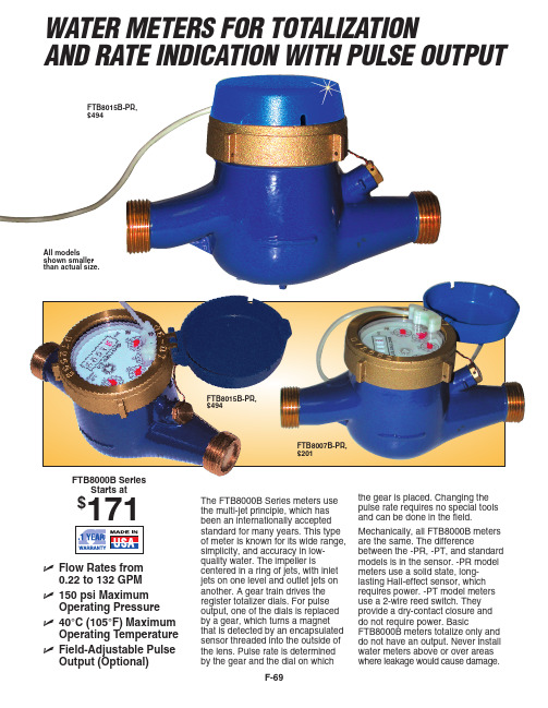
Price NPT Size
(GPM)
(Default Setting)
FTB8007B
$171
3⁄4
0.22 to 22
None, total only
FTB8010B
281
1
0.44 to 52
None, total only
FTB8015B
471
11⁄2
0.88 to 88
None, total only
11⁄4 1
11⁄2 30 (113⁄4) 45 (175⁄8)
2 11⁄2
2 30 (113⁄4) 45 (175⁄8)
21⁄2 2
Pressure drop in P.S.I.
Typical Pressure Drop Curve
20 15
NPT Size
3⁄4
1
11⁄2
2
10
20*
—
—
—
5
Pulses per
1
FTB8007B-PR
201
3⁄4
0.22 to 22
1
FTB8010B-PR
281
1
0.44 to 52
1
FTB8015B-PR
494
11⁄2
0.88 to 88
1
FTB8020B-PR
619
2
1.98 to 132
1
ES-2022
140 Reference Book: Water Resources Handbook
)5$1&( ZZZRPHJDIU
*(50$1< ZZZRPHJDGH 'HFNHQSIURQQ *HUPDQ\
- 1、下载文档前请自行甄别文档内容的完整性,平台不提供额外的编辑、内容补充、找答案等附加服务。
- 2、"仅部分预览"的文档,不可在线预览部分如存在完整性等问题,可反馈申请退款(可完整预览的文档不适用该条件!)。
- 3、如文档侵犯您的权益,请联系客服反馈,我们会尽快为您处理(人工客服工作时间:9:00-18:30)。
BWT-1B步进式可编程调速器说明书重庆水轮机厂水电控制设备分公司2010.9目录一、系统概述-----------------------------------------------------------------------------------------------------------------2二、调速系统的技术标准--------------------------------------------------------------------------------------------------2三、微机调速器主要技术性能和参数-----------------------------------------------------------------------------------21)基本技术参数------------------------------------------------------------------------------------------------------2 2)调节规律------------------------------------------------------------------------------------------------------------3 3)机械液压部分主要参数------------------------------------------------------------------------------------------3 4)电源电压------------------------------------------------------------------------------------------------------------3 5)油压装置主要技术参数------------------------------------------------------------------------------------------3 6)主要配置------------------------------------------------------------------------------------------------------------3 7)技术指标------------------------------------------------------------------------------------------------------------3 四、调速系统的工作性能-------------------------------------------------------------------------------------------------41)主要功能------------------------------------------------------------------------------------------------------------5 2)在线故障诊断功能------------------------------------------------------------------------------------------------6 3)离线功能------------------------------------------------------------------------------------------------------------6 4)孤立电网------------------------------------------------------------------------------------------------------------6 5)故障保护------------------------------------------------------------------------------------------------------------6 6)显示及操作功能---------------------------------------------------------------------------------------------------6 7)抗干扰措施---------------------------------------------------------------------------------------------------------7 8)计算机接口功能---------------------------------------------------------------------------------------------------7 五、调速系统的组成-------------------------------------------------------------------------------------------------------71)整体布置------------------------------------------------------------------------------------------------------------7 2)调节规律------------------------------------------------------------------------------------------------------------8 3)电气部分------------------------------------------------------------------------------------------------------------8 4)软件------------------------------------------------------------------------------------------------------------------11 5)步进电机及驱动器------------------------------------------------------------------------------------------------11 6)电气反馈------------------------------------------------------------------------------------------------------------12 7)机械部分------------------------------------------------------------------------------------------------------------12六、实验-----------------------------------------------------------------------------------------------------------------------13七、技术服务和人员培训--------------------------------------------------------------------------------------------------141)现场技术服务------------------------------------------------------------------------------------------------------14 2)服务承诺------------------------------------------------------------------------------------------------------------14 3)人员培训------------------------------------------------------------------------------------------------------------14一、系统综述随着经济建设的发展,我国的电力工业正迅速发展。
电力系统的规模日益扩大,发电设备的容量也相应增大,系统的运行方式的变化越来越频繁。
为了更好地保证安全,经济运行并保证电能质量,电力系统运行对自动控制装置提出了更高的要求。
BWT-1B型步进微机调速控制器正是专为水电站水轮发电机组设计的一种新型控制器,具有结构简单、抗干扰能力强、可靠性高、调节品质好、功能全、免维护等特点。
解决了以前调速器存在的抗干扰能力差,电液转换器易卡阻,机械杠杆复杂等缺点,使调速器在水电站可靠而稳定地自动运行,向无人值班电站发展。
BWT-1B型步进微机调速器工作油压为2.5~4.0Mpa,操作功可分为3000N.m、6000 N.m、10000 N.m、18000 N.m、30000N.m、35000 N.m 、50000 N.m、55000 N.m 、60000 N.m 、75000 N.m;调速器的接力器一般为内置式。
电气控制部分采用了先进的自适应式PID控制方式,先进的数字式测频方式,全闭环的随动系统控制、友好的中文人机对话接口;使水轮发电机组安全稳定地运行在各种运行工况下,实现机组的自动和手动开机、并网发电、紧急停机等功能,并按照系统和电站的要求进行机组的频率和开度的调节。
二、调速系统的技术标准1.《水轮机电液调节系统及装置技术规程》DL/563-1995;2.《水轮机调速器与油压装置试验验收规程》GB/T 9652.2-1997;3.《水轮机调速器与油压装置技术条件》GB/T 9652.1-1997;4.《大中型水轮机组自动化元件及系统基本技术条件》GB/T 11805-89。
三、微机调速器主要技术性能和参数1.基本技术参数1) 转速调整范围:±10%n e2) 永态转差系数bp: 0~10%3) 频率给定:50±5HZ4) 比例增益Kp:1~605) 积分增益Ki:1~30 l/s6) 微分增益KD:0~0.4s7) 开度给定:0~100%8) 电气开度:0~100%9) 人工失灵区:0~±3Hz10) 步进电机零漂小于0.01mm11) 转速死区:不大于0.05%12) 导叶接力器全开全关行程时间:3~25s(可调)2.调节规律:PID3.机械液压部分主要参数主配压阀直径:mm主配压阀最大行程:mm工作油压:Mpa油质采用L-TSA46汽轮机油。
