Oplink_APODWDMGFF产品介绍
DWDMGFF等光模块扫描测试系统
DWDMGFF等光模块扫描测试系统
DWDM/GFF等光模块扫描测试系统
基于优西仪器的DWDM、GFF等光器件扫描测试应⽤系统;
该测试系统通过IPC的USB总线管理三款优西仪器,实现光器件的⾃动扫描测试。
⼯作原理如下:1. GM8036 激光扫描光谱分析仪:内部集成的可调激光光源与光功率计,可实现快速的“波长-损耗”
扫描功能,由于GM8036 ⾃带了两路功率计,本系统⽀持对DUT的透、反射通道同时快速扫描。
由应⽤软件设定扫描的起始波长、步长、扫描次数等参数,实现联机⾃动扫描功能。
2. 扫描结束后,应⽤软件对扫描的原始数据进⾏分析处理,使⽤户可以更加直观的看到测量结果;
3. GM8012 双通道光功率计:系统还使⽤了GM8012 的⼀个通道测量RL、DIR等参数;
4. GM8015电动式偏振发⽣器:在测量PDL参数时,GM8015偏振控制器产⽣不同状态下的偏振能够
使PDL的测量结果更加精确。
D-Link无线产品系列

支持WPA、AES加密标准
产品卖点
卖点一:支持多种工作模式。
DWL-8200AP支持无线AP、无线点对点网桥、无线点对 多点网桥工作方式,能灵活的适应多种不同的工作环境。
产品卖点
卖点二:支持多SSID
无线网络的安全问题越来越受到关注,多SSID能够在同一 台AP上,为不同的用户群提供不同个SSID,从而增加网络的 安全性。同时,多SSID还支持VLAN功能,让无线网络用户可 以和有线网络用户统一进行VLAN划分。
产品卖点
卖点五:支持SSID广播取消及MAC地址过滤
DWL-8200AP支持SSID广播取消功能,这样陌生人不会轻易 发现你的网络;另外,MAC地址过滤功能允许你只把合法的用 户接入到网络里面来,从而增加网络的安全性。
DWL-3200AP
Contents
产品定位
产品描述
产品卖点
产品定位
附录:技术介绍
DWL-7700AP
Contents
产品定位
产品描述
产品卖点
产品定位
双频三模无线AP,支持IEEE802.11a/b/g三种标准
适用于机场、酒店等热点地区
产品描述
DWL-7700AP支持IEEE802.11a/b/g标准,最高速率108M
输出功率:23dBm(MAX)
产品卖点
卖点三:支持WPA安全标准
安全性对于无线局域网来说至关重要, WPA比WEP具有更 安全的特性,它使用IEEE802.1x提供用户身份验证,使用TKIP 或AES为无线局域网的数据提供更好的加密保护。
产品卖点
卖点四: 支持PoE功能
Power over Ethernet(以太网供电技术)越来越广泛地被 应用到像无线AP、网络摄像机等小型网络设备中。它的特点是 直接从以太网线获得电力,而不用单独铺设电力线,以简化系 统布线,降低网络基础设施的建设成本。
碧云天生物技术pCMV-N-Flag产品说明书
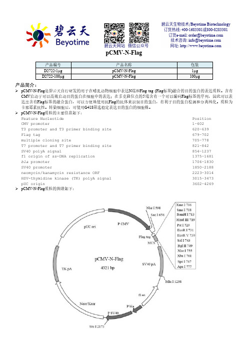
pCMV-N-Flag产品编号 产品名称 包装 D2722-1µg pCMV-N-Flag 1µg D2722-100µgpCMV-N-Flag100µg产品简介:pCMV-N-Flag 是碧云天自行研发的用于在哺乳动物细胞中表达N 端和Flag tag (Flag 标签)融合的目的蛋白的表达质粒。
含有CMV 启动子可以高效启动目的蛋白在细胞中的表达;在多克隆位点的5'端含有一个可以编码Flag 标签的序列,因此可以表达出含有Flag 标签的融合蛋白,可以方便地使用抗Flag 的抗体来识别目的蛋白,有利于目的蛋白检测和分离纯化。
质粒为卡那霉素抗性。
转染细胞后,可使用G418筛选稳定表达目的蛋白的细胞株。
pCMV-N-Flag 质粒的主要信息如下:Feature Nucleotide Position CMV promoter 1–602 T3 promoter and T3 primer binding site 620–639 Flag tag 679–702 multiple cloning site 705–778 T7 promoter and T7 primer binding site 821–842 SV40 polyA signal 854–1237 f1 origin of ss-DNA replication 1375–1681 bla promoter 1706–1830 SV40 promoter 1850–2188 neomycin/kanamycin resistance ORF 2223–3014 HSV-thymidine kinase (TK) polyA signal 3015–3473 pUC origin 3602–4269 pCMV-N-Flag 质粒的图谱如下:碧云天生物技术/Beyotime Biotechnology 订货热线: 400-1683301或800-8283301 订货e-mail :******************技术咨询: *****************网址: 碧云天网站 微信公众号pCMV-N-Flag的多克隆位点的详细图谱如下:Flag tag __SacI M D Y K D D D D K651 GAGCTCCACC GCGGTGGCGG CCGCCATGGA TTACAAGGAT GACGACGATACTCGAGGTGG CGCCACCGCC GGCGGTACCT AATGTTCCTA CTGCTGCTATXmaI PstISmaI BamHI HindIII EcoRI EcoRV SalI BglII701 AGAGCCCGGG CGGATCCAAG CTTCTGCAGG AATTCGATAT CGTCGACAGATCTCGGGCCC GCCTAGGTTC GAAGACGTCC TTAAGCTATA GCAGCTGTCTXhoI XbaI ApaI751 TCTCTCGAGT CTAGAACTAG TGGGCCCGGT ACCTTAATTA ATTAAGGTACAGAGAGCTCA GATCTTGATC ACCCGGGCCA TGGAATTAAT TAATTCCATGpCMV-N-Flag中没有的酶切位点(Restriction enzymes that do not cut pCMV-N-Flag)包括:Afl II Age I Ahd I Asc I Bbs I Bbv II Blp I Bsg I BsiW I BsmB I BspM II BsrG I BssH II Bst1107 I BstE II Ear I Eco47 III Eco72 I EcoN I Esp I Fse I Nru I PflM I Pme I Pml I PpuM I Psp1406 I Sap I Sca I Spl IpCMV-N-Flag中的单酶切位点(Restriction enzymes that cut pCMV-N-Flag once)包括:Nde I CA`TA,TG 241 SnaB I TAC|GTA 347 Nhe I G`CTAG,C 598 Sac I G,AGCT`C 656 Sac II CC,GC`GG 663 BstX I CCAN,NNNN`NTGG 664 Not I GC`GGCC,GC 669 PspA I C`CCGG,G 706 Xma I C`CCGG,G 706 Srf I GCCC|GGGC 708 Sma I CCC|GGG 708 BamH I G`GATC,C 713 Hind III A`AGCT,T 719 Pst I C,TGCA`G 729 EcoR I G`AATT,C 731 EcoR V GAT|ATC 739 Sal I G`TCGA,C 743 Acc I GT`MK,AC 744 Bgl II A`GATC,T 749 PaeR7 I C`TCGA,G 755 Xho I C`TCGA,G 755 Xba I T`CTAG,A 761 Spe I A`CTAG,T 767 Bsp120 I G`GGCC,C 773 Apa I G,GGCC`C 777 Pvu I CG,AT`CG 855 Bcl I T`GATC,A 1009 Mun I C`AATT,G 1102 Hpa I GTT|AAC 1115 Mlu I A`CGCG,T 1238 Dra III CAC,NNN`GTG 1468 Sfi I GGCCN,NNN`NGGCC 2127 BseR I GAGGAG 16/14 2170 Stu I AGG|CCT 2173 Cla I AT`CG,AT 2192 Kas I G`GCGC,C 2351 Nar I GG`CG,CC 2352 Ehe I GGC|GCC 2353 Bbe I G,GCGC`C 2355 Msc I TGG|CCA 2434 Tth111 I GACN`N,NGTC 2470 BsrD I GCAATG, 8 2585 Bsp1286 I G,DGCH`C 2655 Rsr II CG`GWC,CG 2868 BsiC I TT`CG,AA 3034 BstB I TT`CG,AA 3034 Bsa I GGTCTC 7/11 3341 HgiE II ACCNNNNNNGGT-1/13 3681 ApaL I G`TGCA,C 3956pCMV-N-Flag质粒中对于插入片段进行测序时,推荐使用的正向测序引物T3和反向测序引物T7的序列如下:T3 primer (620–639): 5' AATTAACCCTCACTAAAGGG 3'T7 primer (821-842): 5' GTAATACGACTCACTATAGGGC 3'pCMV-N-Flag的全序列信息请参考碧云天网站上该质粒的信息。
gff引导滤波 -回复

gff引导滤波-回复什么是引导滤波?引导滤波(guided filter)是一种图像增强技术,也是一种非线性滤波器。
它被广泛应用于图像处理中的去噪、图像增强、边缘保留、图像融合等领域。
引导滤波通过使用引导图像来引导滤波器的滤波过程,从而保留图像的边缘信息并提高滤波效果。
引导滤波的原理如下:给定一个输入图像I和一个引导图像P,引导滤波器首先计算P图像的均值和方差,然后通过对I进行线性变换,使得I的均值和方差与P的相匹配,接着使用这个变换后的图像作为引导图像对I进行滤波。
这样做的好处是可以加强I图像中的边缘信息并减少噪声的干扰。
引导滤波具有以下几个步骤:1. 计算引导图像的均值和方差。
引导滤波的第一步是计算引导图像P的平均值和方差。
这可以通过一个滑动窗口的方式实现,窗口的大小可以根据具体的应用场景来确定。
2. 对输入图像进行归一化。
接下来,需要对输入图像I进行归一化处理,使得它的均值和方差与引导图像P相匹配。
这一步的目的是使得I图像的边缘信息与P图像的边缘信息保持一致。
3. 计算I和P的协方差矩阵。
根据归一化处理后的图像I和引导图像P,计算它们的协方差矩阵。
协方差矩阵可以用来度量两个变量之间的相关性,它的计算可以通过计算领域内的I和P的平均值、方差和协方差项来实现。
4. 计算滤波器系数。
通过计算协方差矩阵的逆矩阵和一个称为相关系数的变量,可以得到滤波器的系数。
相关系数决定了滤波器对于I和P的相对权重。
一般情况下,相关系数越大表示引导滤波器越注重保护边缘信息。
5. 进行滤波操作。
根据计算得到的滤波器系数,对归一化后的输入图像I进行滤波处理,得到最终的滤波结果。
引导滤波可以很好地保护图像的边缘信息,并且对于各种类型的图像处理任务都具有良好的适应性。
其在去噪、图像增强、边缘保留、图像融合等领域的应用广泛,成为图像处理中重要的技术手段之一。
通过将引导图像与输入图像进行关联,引导滤波有效地提高了图像滤波的效果,使得结果更加自然细腻。
光通信设备DWDM系列产品说明书

specification guideSinglemode devicesTable of contentsOverview. (3)NG4 Central Office (DWDM MUX) (4)NG4 Central Office (DWDM MUX) ordering information (5)NG4 Central Office (DWDM MUX) optical specifications (7)NG4 chassis solutions (8)LGX Central Office and OSP DWDM modules (9)LGX Central Office (DWDM MUX) ordering information (10)LGX Central Office (DWDM MUX) optical specifications (11)LGX OSP (DWDM DEMUX) ordering information (12)LGX OSP (DWDM DEMUX) optical specifications (13)LGX rack mounting solutions (14)FOSC A and D trays OSP (DWDM DEMUX) (15)FOSC A and D tray OSP (DWDM DEMUX) ordering information (16)FOSC A and D tray OSP (DWDM DEMUX) optical specifications (17)Flat Pack OSP (DWDM DEMUX) (18)Flat Pack OSP (DWDM DEMUX) ordering information (19)Flat Pack OSP (DWDM DEMUX) optical specification (20)FIST-FDASA2 Trays OSP (DWDM DEMUX) (21)FIST-FDASA2 Tray OSP (DWDM DEMUX) ordering information (22)FIST-FDASA2 Tray OSP (DWDM DEMUX) optical specifications (22)OverviewInstalling new fiber is a costly and time-consuming way to support today’s bandwidth-intense applications. Network operators are seeking ways to adapt their existing fiber infrastructure to support new service, increase network capacity, and guarantee consistent performance. CommScope’s WDM integrated solutions allow network operators to increase capacity on existing networks without adding fiber, reduce costs, improve performance, deploy faster, and accelerate return on investment.Applications·Commercial Ethernet services ·Wireless backhaul services·Distributed access architectures (e.g., R-PHY) ·40/100/400 GbE ready optics·Single and dual fiber network architectures ·Existing fiber infrastructure expansionFeatures·4-, 8-, 10-, 20-, and 40-channel configurations ·Low pair loss when linking CO and OSP products ·100 GHz DWDM ITU channel spacing (ITU-T G694.1) ·Options include express, upgrade, and test portsWavelength division multiplexing (WDM) is a technique that allows network operators to multiplex several optical carrier signals onto a single optical fiber by using different optical wavelengths (i.e., colors) of laser light. Each wavelength carries an individual signal that does not interfere with the other wavelengths. WDM enables bidirectional communications over one strand of fiber, as well as multiplication of capacity. No power or additional fiber is required—making WDM solutions quick and easy to install and maintain. WDM has become the preferred option in telecommunications because it enables the network to increase the bit rate and effective bandwidth without having to add fiber.CommScope’s WDM portfolio includes a variety of form factors, optimal for a wide range of ISP and OSP applications. For example, CommScope’s LGX and NG4 ISP MUX modules can be paired with FOSC, flat pack, FIST -FDASA2, or LGX OSP demux modules.NG4 Central Office (DWDM MUX)CommScope’s single-height DWDM NG4 modules comply to GR-1209 and GR-1221 testing requirements. CommScope’s triple-height DWDM NG4 modules comply to GR-63 testing requirements.CommScope’s NG4 DWDM modules are designed to multiplex 8, 16, 20, and 40 DWDM wavelengths with 100 GHz frequency spacing on the DWDM ITU grid (ITU-T G.694.1). DWDM module options include express port (for wavelengths outside the C-band), upgrade port (for additional DWDM wavelengths), and TX and RX test ports.CommScope’s central office DWDM modules are designed to be used with NG4access universal chassis’, rack mount 1RU, and FACT element options and typically mated with compatible OSP DWDM products. The 40 channel NG4 module is designed to install into the NG4access universal chassis’ only.Single-Height NG4 VAM(8-, 16-, and 20-channel configurations)Triple-Height NG4 VAM (40-channel configuration)NG4 Central Office (DWDM MUX) ordering information• Module orientation required for NG4access universal chassis’ only. (As viewed from rear of chassis)• LEFT orientation standard for FACT NG4 Chassis.• 40 channel NG4 module installs into NG4access universal chassis’ only.• Please contact your local sales or customer service representative if required configuration is not listed above.NG4 Central Office (DWDM MUX) ordering information (continued)• Module orientation required for NG4access universal chassis’ only. (As viewed from rear of chassis)• LEFT orientation standard for FACT NG4 Chassis.• 40 channel NG4 module installs into NG4access universal chassis’ only.• Please contact your local sales or customer service representative if required configuration is not listed above.NG4 Central Office (DWDM MUX) optical specificationsOptical specifications include connector loss.NG4 chassis solutionsNG4 access universal chassisFeatures:·Single 4RU and 2RU chassis for all applications·One single-high VAM per access tray loaded from rear side of chassis/frame·Up to 24 single-high VAMs per 4RU universal chassis. Up to 12 single-high VAMs per 2RU universal chassis ·Can be deployed as a standalone 19”/23” chassis in standard racks ·4RU: 19.1 x 19.73 x 6.93 inch (Width x Depth x Height) ·2RU: 19.1 x 19.73 x 3.48 inch (Width x Depth x Height)NG4 1RU Chassis - All Front AccessFeatures:· 3 trays per chassis·Chassis accepts single high standard NG4 modules (front connectors only) · 6 modules per 1RU chassis ·19-in. or 23-in. rack mount options·19.1 x 13.5 x 1.75 inch (Width x Depth x Height)FACT NG4 ChassisFeatures:·The FACT NG4 element includes two trays·Each element can accommodate two single-height NG4 VAM modules ·524 x 283 x 30.95 mm (Width x Depth x Height)LGX Central Office and OSP DWDM modulesDouble-width LGX module (40-channel configuration)Single-width LGX module (4-, 8-, 10- and 20-channelconfigurations)CommScope’s DWDM LGX modules comply to relevant IEC 61753-1, GR-1209 and GR-1221 testing requirements.CommScope’s 3-inch-deep DWDM modules are designed to multiplex and demultiplex 4, 8, 10, 20 and 40 DWDM wavelengths with 100 GHz frequency spacing on the DWDM ITU grid (ITU-T G.694.1). DWDM module options include express port (for wavelengths outside the C-band), upgrade port (for additional DWDM wavelengths), and TX and RX test ports. OTDR service available on 40 and 20-channel modules. OSP DWDM modules include an auxiliary port that combines both the upgrade and express port to pass wavelengths outside of the C-band and additional DWDM wavelengths.CommScope’s central office DWDM modules are designed to be used with LGX chassis options and typically mated with compatible OSPDWDM products.LGX Central Office (DWDM MUX) ordering information ISP - LGX MUXPlease contact your local sales or customer service representative if required configuration is not listed above.LGX Central Office (DWDM MUX) optical specificationsOptical specifications include connector loss.LGX OSP (DWDM DEMUX) ordering information OSP - LGX DMUXPlease contact your local sales or customer service representative if required configuration is not listed above.LGX OSP (DWDM DEMUX) optical specificationsOptical specifications include connector loss.LGX rack mounting solutionsFeatures:·The LGX 4RU back-to-back chassis holds 14 single-width LGX modules per side or seven dual-width LGX modules per side ·Maximum density of 28 single-width LGX modules or 14 dual-width LGX modules ·19-in. or 23-in. rack mount· 2.5-in., 5-in., or 8-in. recess mounting options ·Dimensions (H x W x D): 6.9 x 17 x 15 inches·LGX pass-through module: Pass-through modules (qty. 2 required) can be mounted anywhere in chassis to allow cables from rear modules to pass to front of chassis.Features:·Maximum density of 14 single-width LGX modules or 7 dual-width LGX modules ·19-in. rack mount·Dimensions (H x W x D): 132.5 x 482 x 235 mm Features:·Holds three single-width LGX modules ·19-inch rack mount·Dimensions (H x W x D): 1.7 x 18.9 x 8.9 inches / 44 x 481 x 225 mm4RU back-to-back chassis3RU chassis1RU chassisFOSC A and D trays OSP (DWDM DEMUX)CommScope’s DWDM FOSC trays comply to GR-1209 and GR-1221 testing requirements.CommScope’s DWDM FOSC trays are designed to demultiplex 4, 8, 10, 20 and 40 DWDM wavelengths with 100 GHz frequency spacing on the DWDM ITU grid (ITU-T G.694.1). DWDM FOSC trays include an auxiliary port for wavelengths outside the C-band and for additional DWDM wavelengths, 250 µm fiber, and no connectors. All channel configurations are designed into FOSC A tray. 40-channel configuration is designed into both FOSC A tray (two-tray design) and FOSC D tray.CommScope’s OSP DWDM FOSC trays are designed to be field-installable into FOSC closures and BUDI wall boxes (FOSC A tray only). OSP FOSC trays are typically mated with compatible central office DWDM modules. Contact CommScope sales representative for further FOSC closure and BUDI wall box product information.FOSC A tray(4, 8, 10, 20 and 40 channel configurations)FOSC D tray (40 channel configuration)FOSC tray adapter (Part Number 760242191)FOSC A and D tray OSP (DWDM DEMUX) ordering informationPlease contact your local sales or customer service representative if required configuration is not listed above.FOSC tray adapterThe FOSC tray adapter allows for the use of FOSC A Tray into a FOSC C or D size splice closure.FOSC A and D tray OSP (DWDM DEMUX) optical specificationsFlat Pack OSP (DWDM DEMUX)CommScope’s DWDM flat packs comply to GR-1209 and GR-1221 testing requirements.CommScope’s DWDM flat packs are designed to demultiplex 4, 8, 10, and 20 DWDM wavelengths with 100 GHz frequency spacing on the DWDM ITU Grid (ITU-T G.694.1). DWDM flat packs include an auxiliary port for wavelengths outside the C-band and for additional DWDM wavelengths, 250µm fiber, and no connectors. CommScope’s DWDM flat pack ships with a holder to install onto FOSC trays (NOVUX tray holder coming in 2023).CommScope’s OSP DWDM flat packs ship with a holder to field install into various closures and wall box solutions. OSP flat packs are typically mated with compatible Central Office DWDM modules.Example of S CASE(10 channel configurations)Example of S CASE installed onto FOSC D TrayFlat Pack OSP (DWDM DEMUX) ordering information OSP-cassette demux 250 µmPlease contact your local sales or customer service representative if required configuration is not listed above.Flat Pack OSP (DWDM DEMUX) optical specificationFIST-FDASA2 Trays OSP (DWDM DEMUX)CommScope’s FIST-FDASA2 DWDM trays comply to relevant IEC 61753-1 testing requirements.CommScope’s FIST-FDASA2 DWDM trays are designed to demultiplex 8 DWDM wavelengths with 100 GHz frequency spacing on the DWDM ITU grid (ITU-T G.694.1). DWDM trays include an upgrade path to add, drop, or pass-through C-band DWDM channels not already in use, i.e., only channels that reside in the band 1530-1565 nm.CommScope’s FIST FDASA2 DWDM trays are designed to be used with FIST-GSS shelves, BUDI wall mount closures, and FIST closures (FIST-GCO2, FIST-GCOG2, FIST-MSC, FIST-EDSA). DWDM trays are typically mated with compatible central office DWDM products.8mm Height FDASA2 Tray(8 channel configurations)FIST-FDASA2 Tray OSP (DWDM DEMUX) ordering information OSP – FIST-FDASA2 DEMUXFIST-FDASA2 Tray OSP (DWDM DEMUX) optical specificationsCommScope pushes the boundaries of communicationstechnology with game-changing ideas and ground-breakingdiscoveries that spark profound human achievement.We collaborate with our customers and partners to design,create and build the world’s most advanced networks. It is ourpassion and commitment to identify the next opportunity andrealize a better tomorrow. Discover more at Visit our website or contact your local CommScope representative for more information.© 2023 CommScope, Inc. All rights reserved. All trademarks identified by ™ or ® are trademarks or registered trademarks in the US and may be registered in other countries. All product names, trademarks and registered trademarks are property of their respective owners. This document is for planning purposes only and is not intended to modify or supplement any specifications or warranties relating to CommScope products or services.。
单模光纤模块驱动芯片-概述说明以及解释

单模光纤模块驱动芯片-概述说明以及解释1.引言1.1 概述单模光纤模块驱动芯片是一种关键性的元件,它在单模光纤通信系统中起到了至关重要的作用。
本文将重点探讨单模光纤模块驱动芯片的原理、应用领域和作用,并对它的重要性和发展前景进行分析。
首先,我们先来了解一下什么是单模光纤模块。
单模光纤模块是一种用于传输光信号的组件,它具有较小的核心直径,能够实现高速、长距离的光信号传输。
与多模光纤模块相比,单模光纤模块在光信号传输方面具有更好的性能,因此在许多领域得到广泛应用。
单模光纤模块驱动芯片作为单模光纤模块的控制和驱动核心,扮演着至关重要的角色。
它主要用于控制光信号的发射和接收过程,将电信号转换成光信号并进行调制。
在单模光纤通信系统中,单模光纤模块驱动芯片的性能将直接影响到系统的传输质量和可靠性。
单模光纤模块驱动芯片的应用领域非常广泛。
首先,在通信领域,它被广泛应用于光纤通信系统中,包括光纤传输网、光纤宽带接入网络等。
其次,在工业控制领域,它也被广泛应用于激光加工、光纤传感器等领域。
此外,在医疗、军事等领域,单模光纤模块驱动芯片也发挥着重要的作用。
总的来说,单模光纤模块驱动芯片在单模光纤通信系统中具有举足轻重的作用。
它不仅能够实现高速、长距离的光信号传输,还能够保证系统的稳定性和可靠性。
随着科技的不断进步,单模光纤模块驱动芯片的发展前景也非常广阔。
未来,我们可以预见,在通信、工业控制、医疗等领域,单模光纤模块驱动芯片将发挥更加重要的作用,并为社会的进步和发展做出更大的贡献。
1.2文章结构文章结构本篇文章主要由引言、正文和结论三部分组成。
1. 引言- 1.1 概述:简要介绍单模光纤模块驱动芯片的背景和作用。
- 1.2 文章结构:本部分,给出文章整体的结构和各个部分的内容概述。
- 1.3 目的:明确本文的目的和意义。
2. 正文- 2.1 单模光纤模块的基本原理:详细介绍单模光纤模块的工作原理和关键技术。
- 2.2 单模光纤模块的应用领域:探讨单模光纤模块在通信、传感等领域的广泛应用。
博晖创新微流控技术及世界上的微流控一体化产品
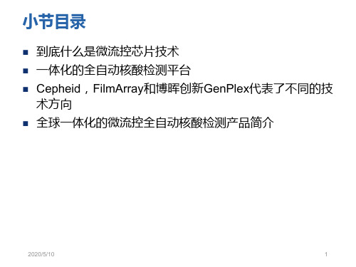
微流控全自 动检测产品 GenPlex
博晖创新
HPV24分 型检测
普通实 验室
全 自 动 核 酸 检 测 产 品 降 低 了 使 用 环 境 要 求
2018/12/11
一体化的全自动核酸检测平台
目前世界上已经商业化的样本处理、核酸提取及扩增检测为 一体的自动化分析仪
博晖创新 GenPlex HPV分型检测 Cepheid GeneXpert, Infinity BioFire FilmArray
微流控技术
GeneXpert
2018/12/11
小节目录
到底什么是微流控芯片技术
一体化的全自动核酸检测平台
Cepheid,FilmArray和博晖创新GenPlex代表了不同的技 术方向
全球一体化的微流控全自动核酸检测产品简介
2018/12/11
1
到底什么是微流控芯片技术
高度交叉的学科领域
核心目的:将生化反应的各反应单元全部集成到只有巴掌甚至指甲 大小的微流控芯片上,实现生化反应的全部过程
芯片上的实验室(lab-on-chip) 微流控芯片技术涉及的应用领域非常广泛
微流控(Microfluidics) 指使用微管道处理或操纵微小流体的系统所涉及的科学和技术。因为具有微型化、 集成化等特征,微流控装置通常被称为微流控芯片(CARD:Chemistry And Reagent Device),也被称为芯片实验室(Lab-on-a-Chip)。
POCT、 小型实 验室、 诊所 设备包含微流样品管、超声装置、注射 健康护理 装置、旋转装置、直角光路设计的特殊 相关的传 定量PCR反应管等几个部分,采用独立的 染病、肿 I-CORE模块设计,每个样品槽都集成有 瘤/遗传学、 独立的加热/冷却系统以及光学信号激发 急诊、性 与检测系统,将样品制备和实时定量PCR 健康 反应全部自动实现 呼吸道病 毒和细菌 (20种) 检测、消 化道/肠胃 病原微生 物检测
华为光传输产品一指禅集0922
OptiX OSN 9500 OptiX OSN 7500 OptiX OSN 3500 OptiX OSN 2500 OptiX OSN 1500
接入业务类型与 接入能力 丰富的槽位资源 组网能力
4(622M POS) ,或者280×STM-1,或者88×GE,或者208×FE(100M),或 者102×E3,或者252×E1 单子架提供22个业务槽位,具备内置波分功能 支持7×10G四纤环网;支持Mesh网络结构、支持链形、环形、相交环、 枢纽形等复杂网络拓扑 设备级保护:交叉、时钟、主控、电源的1+1热备份 网络级保护:MESH恢复、SDH保护(支持2F/4F MSP、SNCP、DNI、共享光
华为光传输产品网络定位
传输
长途WDM 骨 干 层 城域WDM
BWS 1600G
Metro 6100 Metro 6040 OSN 6800
OSN 9500
DXC
OSN 7500
汇 聚 层 10G
Metro 5000 OSN 3500 OSN 3800
2.5G 接 入 层 622M
Metro 3000 OSN 2500 OSN 2000 Metro 1000 OSN 1500
OptiX Metro 5000 OptiX Metro 3000 OptiX OSN 2000 OptiX Metro 1000 OptiX Metro 500
接入能力 组网特性
外型及功耗
为2U),典型配置下功耗小于50W,可直接接入-48V、+24V、 ~110V/220V电源 每个网元既可配置为单个的STM-1/4 TM或ADM系统,也可配置为STM-1、
华为光传输产品系列一览
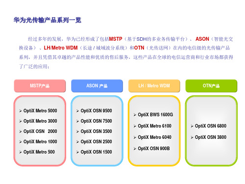
经过多年的发展,华为已经形成了包括MSTP(基于SDH的多业务传输平台)、 ASON(智能光交 换设备) 、LH/Metro WDM(长途 / 城域波分系统)和OTN(光传送网)在内的电信级的光传输产品 系列,并且凭借其卓越的产品性能和优质的售后服务,这些产品在全球的电信运营商和行业市场都获得 了广泛的应用;
IPG光纤激光器说明书
产品质量保证条款谢谢贵公司购买我公司光纤激光器!贵公司需在发货后一个月内确认产品的质量问题,如果不能尽快在一个月内确认的话,就会造成在服务和供货上不必要的麻烦,特别是对于产品不是在美国本土安装的。
我们将给贵公司提供最好的质量和技术支持,在设备的安装和调试操作方面我们有一套详细的方案。
可以通过以下两种途径确认产品的质量:1.将已付资费同时写好地址的信封寄给我方2.直接上网进行确认所有提供的信息都是必须保密的有任何问题可以直接拨打客服电话(508)373-1157安全条款:1.警告鉴于对人体潜在的伤害,请按照规定的程序进行操作,如果不这样做的话,对自己或者他人都会造成伤害2.警示鉴于产品潜在的危险,请按照规定的程序进行操作,如果不这样做的话,对产品自身或者产品的零配件都会有损害3.重要事项关于产品的操作事项请按照说明书逐步操作。
你公司所购买的是400瓦的光纤激光器,执行标准是21 CFR 1040.10,激光波长达到1070纳米,通过光纤输出的激光的功率实际上已经超过400瓦,对人的眼睛和皮肤都会造成伤害,尽管这种辐射是不可见的,但是这种激光对人的角膜的伤害是无法避免的,在设备工作的时候必须带上激光护目镜。
警告:在设备工作中请根据波长范围选择合适的护目镜,请仔细阅读产品上的安全标签,产品的输出功率和波长范围。
有很多供应商为我们提供原材料和零配件。
如果设备经过重新安装或者改进的话,由终端客户负全责。
在设备的调试,操作过程当中如果不按照规定的程序运行,就会造成一定的危害在设备运行过程中,不要随意触动光纤激光器任何部件。
比如光纤准直器。
在靠近激光的位置会从不同的角度发散出激光,这些激光会从不同的镜面物体反射,反射的激光强度都会对人的眼睛和皮肤造成一定的伤害。
激光对人的皮肤,服装都会造成很大的伤害,激光可以引燃比如酒精,汽油之类的溶剂,激光可以进行切割和焊接,在安装和使用设备的时候请谨慎使用一些易燃的材料和气体。
o link蛋白组

o link蛋白组
链接蛋白质组学是一种研究蛋白质在细胞或生物体中的表达、结构、功能以及与其他分子的相互作用的科学技术。
通过分析蛋白质的组成、修饰和相互作用,可以深入了解细胞和生物体的生理和病理过程。
在链接蛋白质组学中,通常采用质谱技术来鉴定和定量蛋白质。
这包括两个主要步骤:蛋白质分离和质谱分析。
蛋白质分离可以采用凝胶电泳、液相色谱等技术,将复杂的蛋白质混合物分离成单个蛋白质样品。
分离后的蛋白质样品可以进行染色或不染色处理,然后用质谱仪进行分析。
质谱分析是一种高灵敏度的方法,可以确定蛋白质的质量、序列、修饰和相互作用。
常用的质谱技术包括质谱仪、液相色谱质谱联用技术(LC-MS/MS)、基质辅助激光解吸电离飞行时间质谱(MALDI-TOF MS)等。
在链接蛋白质组学研究中,还可以通过生物信息学方法对蛋白质数据进行分析和解释。
这包括蛋白质结构预测、功能注释、通路分析等。
链接蛋白质组学在生命科学和医学研究中具有广泛的应用。
它可以帮助我们了解蛋白质在健康和疾病状态下的变化,发现新的生物标志物,揭示蛋白质相互作用网络,并为药物开发和治疗策略的设计提供重要信息。
OPV300 OPV310 OPV314系列850nm垂直光吸收激光器(VCSEL)产品说明书
Vertical Cavity Surface Emitting Laser OPV300, OPV310, OPV310Y, OPV314, OPV314YDescription:The OPV300 / OPV310 / OPV314 series are high performance 850nm Vertical Cavity Surface Emitting Laser (VCSEL). The OPV300 and OPV310 are designed to be utilized for sensing applications as well as air transmission of data. The OPV314 is designed for high speed communication links. The OPV310 / OPV314 combine all the performance advantages of a VCSEL with the addition of a power monitor diode for precise control of optical power. The OPV310 and OPV314 have a back monitor photodiode used for optical power management or optical reception for data communication applications.The OPV300 / OPV310 have a flat lens while the OPV314 has a microbead lens. Refer to mechanical drawings for details.The high performance 850nm VCSEL is designed for applications where low current is required with high on -axis optical power. These product ’s combine features including high speed, high output optical power and concentric beam making it an ideal transmitter for integration into all types of data communications equipment as well as for reflective and transmissive switches.Applications:• Fiber Channel • Gigabit Ethernet • ATM • VSR• Intra -System links• Optical backplane interconnects • Reflective sensing • Interruptive sensing•Long distance spot illuminationFeatures:• 850nm VCSEL Technology • Data rates up to 2.5 Gbps • High thermal stability• Low drive current / high output density • Narrow and concentric beam angle• Recommended for multimode fiber applications •Burned in for communication level reliabilityRoHSAdditional laser safety information can be found on the Optek website. See application bulletin #221.Classification is not marked on the device due to space limitations. See package outline for centerline of optical radiance. Operating devices beyond maximum rating may result in hazardous radiation exposure.OPV314YAbsolute Maximum Ratings (T A = 25° C unless otherwise noted)Electrical SpecificationsNotes:(1) Threshold Current is based on the two line intersection method specified in Telcordia GR -468-Core. Line 1 from 4 mA to 6 mA. Line 2 from 0 mA to 0.5 mA.(2) Series Resistance is the slope of the Voltage -Current line from 5 to 8 mA.(3) Slope efficiency is the slope of the best fit LI line from 5 mA to 8 mA using no larger than .25 mAtest interval points.(4) Using data points taken for slope efficiency above, delta L/delta I shall be calculated for eachadjacent pair of points.Additional laser safety information can be found on the Optek website. See application bulletin #221.Classification is not marked on the device due to space limitations. See package outline for centerline of optical radiance. Operating devices beyond maximum rating may result in hazardous radiation exposure.OPV314YElectrical SpecificationsElectrical Characteristics (T A = 25° C unless otherwise noted)(1)Threshold Current is based on the two line intersection method specified in Telcordia GR-468-Core. Line 1 from 4 mA to 6 mA. Line 2from 0 mA to 0.5 mA.(2)Series Resistance is the slope of the Voltage-Current line from 5 to 8 mA.(3)Slope efficiency, is the slope of the best fit LI line from 5 mA to 8 mA using no larger than .25 mA test interval points.(4)Using data points taken for slope efficiency above, delta L/delta I shall be calculated for each adjacent pair of points.(5)ESD Class 1OPV314YNormalized Output Power vs. Forward CurrentN o r m a l i z e d O u t p u t P o w e r (7m A , 25 °C )PerformanceForward Current (mA)OPV314Y1 2 3 VCSEL PDVCSEL PD1 2 VCSEL OPV300 & OPV310PerformanceOPV314Y1) Tolerances are ±0.005 unlessotherwise specified2) Dimensions in inches [mm]OPV3141 2 3 VCSEL PDVCSEL PD。
智能融合cSoC:多通道FFT共享处理器使用FPGA纤维说明书

Application Note AC381February 20121© 2012 Microsemi Corporation SmartFusion cSoC: Multi-Channel FFT Co-Processor Using FPGA FabricTable of ContentsIntroductionThe SmartFusion ® customizable system-on-chip (cSoC) device integrates FPGA technology with a hardened ARM ® Cortex™-M3 processor based microcontroller subsystem (MSS) and programmable high-performance analog blocks built on a low power flash semiconductor process. The MSS consists of hardened blocks such as a 100 MHz ARM Cortex-M3 processor, peripheral direct memory access (PDMA), embedded nonvolatile memory (eNVM), embedded SRAM (eSRAM), embedded FlashROM (eFROM), external memory controller (EMC), Watchdog Timer, the Philips Inter-Integrated Circuit (I 2C),serial peripheral interface (SPI), 10/100 Ethernet controller, real-time counter (RTC), GPIO block, fabric interface controller (FIC), in-application programming (IAP), and analog compute engine (ACE).The SmartFusion cSoC device is a good fit for applications that require interface with many analog sensors and analog channels. SmartFusion cSoC devices have a versatile analog front-end (AFE) that complements the ARM Cortex-M3 processor based MSS and general-purpose FPGA fabric. The SmartFusion AFE includes three 12-bit successive approximation register (SAR) ADCs, one first order sigma-delta DAC (SDD) per ADC, high performance signal conditioning blocks, and comparators. The SmartFusion cSoCs have a sophisticated controller for the AFE called the ACE. The ACE configures and sequences all the analog functions using the sample sequencing engine (SSE) and post-processes the results using the post processing engine (PPE) and handles without intervention of Cortex-M3 processor.Refer to the SmartFusion Programmable Analog User’s Guide for more details.This application note describes the capability of SmartFusion cSoC devices to compute the Fast Fourier Transform (FFT) in real time. The Multi Channel FFT example design can be used in medical applications, sensor network applications, multi channel audio Spectrum analyzers, Smart Metering, and sensing applications (such as vibration analysis).This example design uses the Cortex-M3 processor in the SmartFusion MSS as a master and the FFT processor in the FPGA fabric as a slave. All three of the SmartFusion cSoC A2F500’s ADCs are used for data acquisition. The example design uses Microsemi’s CoreFFT IP and the advanced peripheral bus interface (CoreAPB3). A custom-made APB3 interface has been developed to connect CoreFFT with the MSS via CoreAPB3. The Cortex-M3 processor uses the PDMA controller in the MSS for the data transfer and thus helps to free up the Cortex-M3 processor instruction bandwidth.A basic understanding of the SmartFusion design flow is assumed. Refer to Using UART with SmartFusion - Microsemi Libero ® SoC and SoftConsole Flow Tutorial to understand the SmartFusion design flow.Introduction . . . . . . . . . . . . . . . . . . . . . . . . . . . . . . . . . . . . . . . . . . . . . . . . 1Design Overview . . . . . . . . . . . . . . . . . . . . . . . . . . . . . . . . . . . . . . . . . . . . . 2Design Description . . . . . . . . . . . . . . . . . . . . . . . . . . . . . . . . . . . . . . . . . . . . 2Implementing Multi Channel FFT on EVAL KIT BOARD . . . . . . . . . . . . . . . . . . . . . . . . . 7Running the Design . . . . . . . . . . . . . . . . . . . . . . . . . . . . . . . . . . . . . . . . . . . . 8Conclusion . . . . . . . . . . . . . . . . . . . . . . . . . . . . . . . . . . . . . . . . . . . . . . . . 9Appendix A – Design Files . . . . . . . . . . . . . . . . . . . . . . . . . . . . . . . . . . . . . . . 10SmartFusion cSoC: Multi-Channel FFT Co-Processor Using FPGA Fabric2Design OverviewThis design example demonstrates the capability of the SmartFusion cSoC device to compute the FFT for multiple data channels. The FFT computation is a complex task that utilizes extensive logic resources and computation time. In general, for N number of channels, N number of FFT IP’s are needed to be instantiated, which in turn utilize more logic resources on the FPGA. A way to avoid this limitation is to use the same FFT logic for multiple input channels.This design illustrates the implementation of a Multichannel FFT to process multiple data channels through a single FFT and store FFT points in a buffer. The FFT computes the input data read from each channel and stores the N-point result in the respective channel’s allocated buffer. The channel multiplexing is done once each channel buffer has been loaded with the FFT length.Computing frequency components for a real time data of six channels is described in this application note. For sampling the input signals the AFE is used and the complex FFT computation is implemented in the fabric of the SmartFusion cSoC device. The Cortex-M3 processor in the MSS of the SmartFusion cSoC handles the buffer management and channel muxing.Figure 1 depicts the block diagram of six channel FFT co-processor in FPGA fabric.Design DescriptionThe design uses CoreFFT for computing the FFT results. You can download the core generator for CoreFFT at /soc/portal/default.aspx?r=4&p=m=624,ev=60.The design example uses a 512-point and 16-bit FFT. A custom-made APB3 interface has been developed to connect CoreFFT IP with the MSS’s FIC. The CoreFFT output data is stored in a 512x32FIFO within the fabric. The FIFO status signals are given in Table 1 on page 3. The status signals indicate that FFT is ready to receive data and data is available in the output of FIFO. These status signals are mapped to the GPIOs in the MSS. The Cortex-M3 processor can read the GPIOs to handle flow control in the data transfer process from the MSS to CoreFFT.Figure 1 • Multi Channel FFT Block DiagramDesign Description3Figure 2 shows the block diagram of logic in the fabric with custom-made APB3 bus.The data valid signal (ifiD_valid) is generated in custom logic whenever the master needs to write data into the input buffer of the FFT to process through the APB3 interface. The FFT_IP_RDY signal indicates the status of the input buffer of the FFT. If the input buffer is full, the FFT_IP_RDY goes low. The master can read the FFT_IP_RDY signal to get the FFT input buffer status. The FFT generates the processed data with a data valid signal (ifoY_valid). The processed data is stored in the FIFO. When FIFO is not ready to receive output data, it can stop the data fetching from the FFT by pulling down the ifiRead_y signal. The status signal FFT_OP_RDY is used to indicate to the master that processed data is available in the FIFO. FFT_OP_RDY goes High whenever processed data is available in the FFT output buffer.The master can use AEMPTY_OUT or EMPTY_OUT to determine whether the FIFO is empty and all the processed data has been read. Refer to the CoreFFT Handbook for more details on architecture and interface signal descriptions.Three ADCs are configured to have two channels, each channel with 100 ksps sampling rate. The external memory is used for input and output buffers. For each channel, one input buffer having length double to the length of FFT i.e. 1024 words and one output buffer having length equal to the length of FFT i.e. 512 words are used. After each channel's input buffer has 512 points required for the full length of the FFT, each channel, one after the other, streams its points from the FIFO through the FFT. During the FFT computational period, the sampled data values of each channel are stored in the second half of the input buffer. Once the FFT computations for the First half of input buffer completes then the points in the second half of the input buffer will be streamed to FFT. This operation utilizes a ping-pong method. The Cortex-M3 processor is used for data management, that is, buffering the sampled points and data routing or muxing of these values to the FFT computation block. Sampling of the real time data is done by the ACE. The PDMA handles the data transfer between the external SRAM (eSRAM) buffers and CoreFFT logic in FPGA fabric.Figure 2 • CoreFFT with APB Slave InterfaceTable 1 • FIFO Status Signals with DescriptionsSignalDescription FFT_IP_RDYFFT is ready to receive the Input from the master processor FFT_OP_RDYProcessed data is ready in output buffer of FFT AEMPTY_OUTOutput FIFO is almost empty EMPTY_OUT Output FIFO is emptySmartFusion cSoC: Multi-Channel FFT Co-Processor Using FPGA Fabric4Figure 3 shows the implementation of multi channel FFT on the SmartFusion cSoC device.Hardware ImplementationThe MSS is configured with an FIC, clock conditioning circuit (CCC), GPIOs, EMC and a UART. The CCC generates 80 MHz clock, which acts as the clock source. The FIC is configured to use a master interface with an AMBA APB3 interface. Four GPIOs in the MSS are configured as inputs that are used to handle flow control in data transfer from MSS to FFT coprocessor. The EMC is configured for Region 0as Asynchronous RAM and port size as half word. The UART_0 is configured for printing the FFT values to the PC though a serial terminal emulation program.ADC0, ADC1, and ADC2 are configured with 12-bit resolution, two channels and the sampling rate is set to approximately 100 KHz. Figure 4 on page 5 shows the ACE configuration window.Figure 3 • Implementation of Multi Channel FFT on the SmartFusion cSoCDesign Description5The APB wrapper logic is implemented on the top of CoreFFT and connected to CoreAPB3. A FIFO of size 512*32 is used to connect to CoreFFT output.CoreAPB3 acts as a bridge between the MSS and the FFT coprocessor block. It provides an advanced microcontroller bus architecture (AMBA3) advanced peripheral bus (APB3) fabric supporting up to 16APB slaves. This design example uses one slave slot (Slot 0) to interface with the FFT coprocessor block and is configured with direct addressing mode. Refer to the CoreAPB3 Handbook for more details on CoreAPB3 IP .For more details on how to connect FPGA logic MSS, refer to the Connecting User Logic to the SmartFusion Microcontroller Subsystem application note.The logic in the FPGA fabric consumes 18 RAM blocks out of 24. We cannot use eSRAM blocks for implementing CoreFFT as the transactions between these SRAM blocks and FFT logic are very high and are time critical.Figure 5 on page 6 illustrates the multi channel FFT example design in the SmartDesign.Figure 4 • Configure ACESmartFusion cSoC: Multi-Channel FFT Co-Processor Using FPGA Fabric6Table 2 summarizes the logic resource utilization of the design on the A2F500M3F device.Software ImplementationThe Cortex-M3 processor continuously reads the values from ACE and stores the values into the input buffers. If the first 512 points are filled then the processor initiates the FFT process. In the FFT process,the input buffers are streamed one after other to the CoreFFT with the help of PDMA. Using another channel of PDMA the output of FFT is moved to the corresponding channel output buffers.During the FFT process the Cortex-M3 processor stores the sampled values into the second half of the input buffers. Once the FFT process completes the first half of input buffer, then the second half of the input buffer are streamed to CoreFFT.Figure 5 • SmartDesign Implementation of Multi Channel FFTTable 2 • Logic Utilization of the Design on A2F500M3FCoreFFTOther Logic in Fabric Total Ram Blocks14418 (75%)Tiles 78424718313 (72.1%)Implementing Multi Channel FFT on EVAL KIT BOARD7The CALL_FFT(int *) application programmable interface (API) initiates the PDMA to transfer input buffer data to the FFT in the fabric. Before initiating PDMA it checks for FFT whether or not it is ready to read the data. The CALL_FFT(int *) API also checks if the output FIFO is empty so that all the FFT out values have been already read. When the input buffer has points equal to the full length of FFT, then it will be called.The Read_FFT() API initiates the PDMA for reading the FFT output values from FIFO in fabric to the corresponding output buffer. After reading all the values it calls the CALL_FFT() API with the next channel buffer to compute the FFT for next channel. This is done for all channels. After completion of FFT computation for all channels, if the continuous variable is not defined, it will print the FFT output values on the serial terminal. When FFT_OP_READY interrupt occurs then this API will be called.The GPIO1_IRQHandler() interrupt service routine occurs on the positive edge of FFT_OP_READY signal. It calls Read_FFT() API. This interrupt mechanism is used to read the sample values continuously while computing the FFT.If continuous variable is defined, then the FFT is computed without any loss of data samples. If #define continuous line is commented then after every completion of FFT computation of all channels the FFT output is printed on serial terminal. The printed values are in the form of complex numbers.The ping-pong mechanism is used for input data buffer to store the samples continuously. For each channel the input buffer length is double of the full FFT length. While computing the FFT for the first half of the buffer, the new sample values are stored in the second half of the input buffer and while computing the FFT for second half of buffer, the new sample values are stored in first half of the input buffer.Customizing the Number of ChannelsYou can change the design depending on your requirement. Configure the ADC (Figure 4 on page 5)with the required number of channels and required sampling rate. In SoftConsole project change the parameter value NUM_CHANNELS according to the ADC configuration. Edit the main code for reading ADCs data into buffers according to ACE configuration.Throughput CalculationsThe actual time to get 512 samples with 100 ksps is 5.12 ms. Each channel is configured to 100 ksps, so for every 5.12 ms we will have 512 samples in the input buffers.The actual time taken to compute the FFT for each channel is the sum of time taken to transfer 512points to CoreFFT, FFT computation time, and time to read FFT output to the output buffer.•Total time for computing FFT = (time taken to receive 512 data + computational latency for 512points + time taken to store 512 data) = 512*5 + 23292 + 512*5 =28412 clks •Time to compute FFT for 6 channels = 28412*6 = 170472 clksTime to compute FFT for six channels is 2.1309 ms (If CLK is 80 MHz). It is less than half the sample rate of 5.12 ms.If only one channel is configured with maximum sampling rate (600 ksps) then time to get 512 samples with 600 ksps is 0.853 ms. Time to compute FFT for these 512 samples is 0.355 ms. If you configure three ADCs with maximum sampling rate (1800 ksps) then time to compute the FFT for these three channels will be 1.065 ms which is higher than the sampling time. In this there is a loss of some samples.The design works fine up to 1440 ksps.Implementing Multi Channel FFT on EVAL KIT BOARDTo implement the design on the SmartFusion Evaluation Kit Board the FFT must be 256 point and 8 bit because the A2F200 device has less RAM blocks and logic cells. The ADC channels must be selected for only ADC0 and ADC1. Figure 6 on page 8 shows the implementation of multi channel FFT on the SmartFusion cSoC (A2F200M3F) device.SmartFusion cSoC: Multi-Channel FFT Co-Processor Using FPGA Fabric8Table 3 summarizes the logic resource utilization of the design with 256 points 8-bit FFT on A2F200M3F device.Running the DesignProgram the SmartFusion Evaluation Kit Board or the SmartFusion Development Kit Board with the generated or provided *.stp file (refer to "Appendix A – Design Files" on page 10) using FlashPro and then power cycle the board.For computing continuous FFT values for the all six signals sampled through the ADCs, uncomment the line #define continuous in the main program. The FFT output values are stored in the rdata buffer. This buffer is updated for every computation of FFT.For printing the FFT values on serial terminal (HyperTerminal or PuTTy), comment the line #define continuous in the main program.Figure 6 • Implementation of Multi Channel FFT on the SmartFusion Evaluation Kit BoardTable 3 • Logic Utilization of the Design on A2F200M3F DeviceCoreFFTOther Logic in Fabric Total Ram Blocks718 (100%)Tiles 3201853286 (66%)Conclusion9Connect the analog inputs to the SmartFusion Kit Board with the information provided in Table 4.Invoke the SoftConsole IDE, by clicking on Write Application code under Develop Firmware in Libero ®System-on-Chip (SoC) project (refer to "Appendix A – Design Files") and launch the debugger. Start HyperTerminal or PuTTY with a baud rate of 57600, 8 data bits, 1 stop bit, no parity, and no flow control.If your PC does not have the HyperTerminal program, use any free serial terminal emulation program such as PuTTY or Tera Term. Refer to the Configuring Serial Terminal Emulation Programs Tutorial for configuring the HyperTerminal, Tera Term, or PuTTY .ConclusionThis application note describes the capability of the SmartFusion cSoC devices to compute the multi channel FFT. The Cortex-M3 processor, AFE, and FPGA fabric together gives a single chip solution for real time multi channel FFT system. This design example also shows the 6-channel data acquisition system.Table 4 • SettingsChannelEvaluation Kit Development Kit Channel 173 of J21 (signal header)ADC0 of JP4Channel 274 of J21 (signal header)ADC1 of JP4Channel 377 of J21 (signal header)77 of J21 (signal header)Channel 478 of J21 (signal header)78 of J21 (signal header)Channel 585 of J21 (signal header)Channel 686 of J21 (signal header)Figure 7 • FFT Output Data for 1 kHz Sinusoidal Signal on PUTTYSmartFusion cSoC: Multi-Channel FFT Co-Processor Using FPGA Fabric10Appendix A – Design FilesThe Design files are available for download on the Microsemi SoC Product Groups website:/soc/download/rsc/?f=A2F_AC381_DF.The design zip file consists of Libero SoC projects and programming file (*.stp) for A2F200 and A2F500.Refer to the Readme.txt file included in the design file for directory structure and description.51900249-0/02.12© 2012 Microsemi Corporation. All rights reserved. Microsemi and the Microsemi logo are trademarks of Microsemi Corporation. All other trademarks and service marks are the property of their respective owners.Microsemi Corporation (NASDAQ: MSCC) offers a comprehensive portfolio of semiconductor solutions for: aerospace, defense and security; enterprise and communications; and industrial and alternative energy markets. Products include high-performance, high-reliability analog and RF devices, mixed signal and RF integrated circuits, customizable SoCs, FPGAs, and complete subsystems. Microsemi is headquartered in Aliso Viejo, Calif. Learn more at .Microsemi Corporate HeadquartersOne Enterprise, Aliso Viejo CA 92656 USAWithin the USA: +1 (949) 380-6100Sales: +1 (949) 380-6136Fax: +1 (949) 215-4996。
深圳市奥联 APN GW 说明书

APN GW使用说明书Powered by APN GW TM Architecture深圳市奥联科技有限公司APN GWInstallation & Configuration GuideFor APN GW 200/200A/2000/2500/NP/Series【Text Part Number: T07-03-17-G3】Documentation also available on CR-ROM and the Website声明本公司对本手册的内容保留在不通知用户的情况下更改的权利。
其版权归深圳市奥联科技有限公司所有。
未经本公司书面许可,本手册的任何部分不得以任何形式手段复制或传播。
NOTICESShenzhen Olym-tech Company Limited reserves the right to make any changes in specifications and other information contained in this publication without prior notice and without obligation to notify any person or entity of such revisions or changes.©Copyright 2002-2003 by Olym-tech. Co., Ltd. All Right Reserved.No part of this publication may be reproduced or transmitted in any form or by any means, electronic or mechanical. Including photocopying, recording, or information storage and retrieval systems, for any purpose other than the purchaser’s personal use, without express written permission of Olym Co. Ltd.(APN GW TM是深圳市奥联科技有限公司注册商标。
o-link蛋白芯片
o-link蛋白芯片O-Link蛋白芯片是一种新型的蛋白质分析技术,它可以同时检测数千种蛋白质,具有高灵敏度、高通量、高精度和高可重复性的特点。
下面我们来了解一下O-Link蛋白芯片的历史背景、原理和应用。
一、历史背景O-Link蛋白芯片是由瑞典Uppsala大学的研究人员发明的。
2002年,瑞典Uppsala大学的研究人员开发了一种名为Proximity Extension Assay(PEA)的技术,该技术可以将两个亲和性较高的抗体连接在一起,形成一种新的双抗体,然后将这种双抗体与待检测的蛋白质反应,最终通过荧光信号检测蛋白质的存在。
这种技术具有高灵敏度、高特异性和高通量的特点,被广泛应用于蛋白质组学研究领域。
二、原理O-Link蛋白芯片的原理是基于Proximity Extension Assay(PEA)技术的。
首先,将两个亲和性较高的抗体连接在一起,形成一种新的双抗体。
然后,将这种双抗体与待检测的蛋白质反应,形成一种新的复合物。
接下来,将这种复合物与一种名为OL INK® Detection Reagents的试剂盒反应,该试剂盒包含了一系列的DNA引物和荧光标记的探针。
在PCR扩增的过程中,引物与探针结合,形成一种新的DNA复合物,荧光信号随之产生。
最终,通过荧光信号检测蛋白质的存在。
三、应用O-Link蛋白芯片可以广泛应用于生命科学研究领域,如疾病诊断、药物研发、生物标志物鉴定等。
具体应用包括:1. 疾病诊断:O-Link蛋白芯片可以检测数千种蛋白质,可以用于疾病的早期诊断和预测。
2. 药物研发:O-Link蛋白芯片可以用于药物的靶点鉴定和药效评估。
3. 生物标志物鉴定:O-Link蛋白芯片可以用于生物标志物的鉴定和筛选,有助于疾病的早期诊断和治疗。
总之,O-Link蛋白芯片是一种新型的蛋白质分析技术,具有高灵敏度、高通量、高精度和高可重复性的特点,可以广泛应用于生命科学研究领域。
光电复合POF产品介绍20231115

主要设备(吸顶AP)
AX3000双频Wi-Fi 6无线吸顶式AP(2.5G口) TL-XAP3020HC易展版
2.5G光电复合接口,数据传输、设备供电,光电复合缆一缆解决, 采用光纤传输,突破千兆限制,大大提升有线传输速率,轻松实 现全屋超千兆组网。端口采用隐藏结构,巧妙隐藏传输线路,使 用安装点位整洁美观。
主要规格
裸机尺寸(长×宽×高) 接口
PoF性能 输入电源
226(W)x131(D)x35(H) mm
1个2.5G RJ45 WAN口 1个2.5G RJ45 WAN/LAN口 8个2.5G 光电复合 LAN口(支 持PoF对外供电)
单口最大输出30W 整机最大输出101W
53.5VDC/2.4A
典型带机量 带宽
主要设备(面板AP)
AX3000双频Wi-Fi 6无线面板式AP(2.5G口) TL-XAP3030HI易展版
主要设备(吸顶AP)
AX3000双频Wi-Fi 6无线吸顶式AP(2.5G口) TL-XAP3020HC易展版
主要规格
裸机尺寸(长×宽×高)
Φ235×43.3mm(不含安装件)
裸机重量 接口
光电复合 POF产品介绍
系统架构
支持IPTV功能,满足机顶盒接入需求
支持网口与IPTV口复用,配合POF-AC一体化路由器, 可将无线AP网口设置为IPTV口(需 在POF-AC一体化路由器上配置)。
光电复合缆集中供电
ap组网美观大方、传输稳定、管理便捷
主要设备(光电复合路由器)
2.5G光电复合PoF·AC一体VPN路由器 TL-R5210PE-H
整机功耗
0.49kg(不含配件、包装)
1 个2.5G光电复合接口(支持光 电复合缆供电)
Oplink_APOD(WDM&GFF)产品介绍

0.5 0
1528
1531
1534
1537
1540
1543
1545
1548
1551
1554
1557
1560
-0.5 -1 -1.5 -2 -2.5 -3 -3.g et) @ 23 度 IL @ 23 度 EF @ 23 度
GFF谱线图(含参数定义)
结论
1. APOD WDM在各个方面都表现了较大的 优势,比如结构简单、性能可靠,并 随着 欧盟对有铅产品实施的各种规定 (ROHS),APOD平台势必成为每个公 司主要的生产平台之一; 2. APOD 平台一个新的生产平台,在很多 方面仍需要不断的完善,如工艺的更 新、胶的质量控制等等。
0.5 0
1528
1531
1534
1537
1540
1543
1545
1548
1551
1554
1557
1560
-0.5 -1 -1.5 -2 -2.5 -3 -3.5 -4
1563
IL(targ et) @ 23 度 IL @ 23 度 EF @ 23 度
GFF谱线图(含参数定义)
GFF简介
GFF:Gain Flattening Filter
(一)filter原理:多光束干涉 (二)基于filter的WDM结构: APOD WDM就是靠玻璃管和胶将 Filter/Lens/Pigtail部件封装起来
Dual Fiber Pigtail C- Lens Filter
Single Fiber Pigtail
工艺流程
WDM工艺流程
WDM关键参数
APOD WDM、GFF产品简介
提纲
GFocus固定式读码器产品简介

一维码 CODE39、CODE128、CODE93、CODE11、CODEBAR、INT2OF5、
MTX2OF5、MSI、PHARMA、STA2OF5、UPC、EAN
通信
RS232 以太网 USB
外壳防护等级
IP65
尺寸
40*32*24mm
产品系列:BVC
BVC固定式读码器是BARV系列读码器中的体积非常小巧的一员。BVC采用高质量的90万像 素CMOS图像传感器,可以每秒高达45帧的速度采集高质量的图像。集成LED定制角度光源实现 更均匀的打光。采用独特的光学设计,实现高清晰度、大景深、高均匀度的成像。集成最优 异的光学、算法和电子设计,加上紧凑的结构设计,BVC可以轻松解决电子制造、追溯等行业 中安装空间有限但有需要卓越读码能力所面对的难题,并且可以轻松解决反光材质码的要求。
凭借优异的光学、算法和电子设计,加上紧凑的机身,BV1能轻松解决电子制造、追溯等 行业读码的需求,再加上BV1小巧的身段,可以有效解决现场安装空间过于紧凑的问题,大大 提高工作效率。
特点: Ø 选配自动对焦 Ø 常规DPM读码 Ø 快速运动读码 Ø 超小安装尺寸 Ø 以太网通讯
系列
BV1
BV1W
类别
IP65
0°至45°
-20°至70°
92x61x 43mm
92x61x50mm
产品系列:BV5X
BV5X固定式读码器是BV系列读码器中性能超强大的一款。BV5X采用高质量的200万像素或 500万像素分辨率图像传感器,可以每秒最高60帧的速度采集高质量的图像。集成了专利技术 的液态透镜可以在35mm-600mm工作范围内自动对焦高速读码。专业的红蓝双波长LED光源的设 计,对镭雕码(DPM)读取有着优异性能。BV5X采用独特的光学设计,实现高清晰度、大景深、 高均匀度的成像。同时搭配多种镜头,实现读取最小0.18*0.18mm的二维码。采用全局快门技 术,实现高速运动状态读取。BV5X卓越读码能力可以轻松解决电子制造、追溯等行业所面对 的难题,适合应用于电子装配、新能源、液晶屏、药品追溯等行业。
- 1、下载文档前请自行甄别文档内容的完整性,平台不提供额外的编辑、内容补充、找答案等附加服务。
- 2、"仅部分预览"的文档,不可在线预览部分如存在完整性等问题,可反馈申请退款(可完整预览的文档不适用该条件!)。
- 3、如文档侵犯您的权益,请联系客服反馈,我们会尽快为您处理(人工客服工作时间:9:00-18:30)。
GFF简介
GFF:Gain Flattening Filter
0.5 0
-0.5 -1
-1.5 -2
-2.5 -3
-3.5 -4
GFF谱线图(含参数定义)
IL(targ et) @ 23 度
IL @ 23 度
EF @ 23 度
1528 1531 1534 1537 1540 1543 1545 1548 1551 1554 1557 1560 1563
Wavelength Thermal shifting
R-IL(dB) T-IL(dB) R-IS(dB) T-IS(dB)
RL(dB) DIR@Passband(dB)
CWDM
100G DWDM
16~18 0.37~0.43 -0.20+0.30 0.00~+0.30
3pm/℃
<1pm/℃
0.3 0.5 13 40 50 50以上
0.4 0.7 13,15 25,30 50 40~45
CWDM谱线图(பைடு நூலகம்参数定义)
DWDM谱线图(含参数定义)
WDM关键参数
-10
-20
-30
-40
-50
-60
0
DWDM谱线图(含参数定义)
1558 1559 1559 1560 1560 1561 1561 1562 1563 1563 1564 1564 1565 1566
(二)波分复用器的分类:
(1)DWDM:Dense WDM(密集波分复用,50G/100G/200G等) 信道间隔:0.2nm~1.6nm 信道中心波长:ITU标准
(2)CWDM:Coarse WDM(稀疏波分复用) 信道间隔:20nm 信道中心波长:ITU标准,1271~1611共18个通道
(3)MWDM:Micro-Optic WDM(SPF,LPF,BPF) (4)HWDM:High-isolation WDM(高隔离度波分复用)
GFF简介
GFF:Gain Flattening Filter
0.5 0
-0.5 -1
-1.5 -2
-2.5 -3
-3.5 -4
GFF谱线图(含参数定义)
IL(targ et) @ 23 度
IL @ 23 度
EF @ 23 度
结论
1. APOD WDM在各个方面都表现了较大的 优势,比如结构简单、性能可靠,并 随着 欧盟对有铅产品实施的各种规定 (ROHS),APOD平台势必成为每个公 司主要的生产平台之一;
APOD WDM、GFF产品简介
提纲
• 应用简介 • 产品结构 • 工艺流程 • 参数分布
应用简介
(一)波分复用的含义:
波分复用(Wavelength Division Multiplexing)是将两种或多种 不同波长的光信号经复用器(Multiplexer)汇合在一根光纤上 传输、或将汇合的各种光波经解复用器(Demultiplexer)进行 分离的技术。
应用简介
(三)波分复用实现方法: (1)薄膜滤光片(TFF,光联现用的技术,核心部件是filter) (2)熔融拉锥型(FBT) (3)光纤光栅型 (4)阵列波导光栅(AWG)
1,2 ,…… n
m
WDM
1,2 ,… m-1, m+1,… n
产品结构
Substrate
(一)filter原理:多光束干涉 (二)基于filter的WDM结构:
APOD WDM就是靠玻璃管和胶将 Filter/Lens/Pigtail部件封装起来
Film Coating
Filter示意图
Dual Fiber Pigtail C- Lens Filter
Single Fiber Pigtail
工艺流程
WDM工艺流程
WDM关键参数
WDM种类 参数种类
BW@0.5dB(nm) CW精度(nm)
R-IL
T-IL
WDM关键参数
-10
-20
-30
-40
-50
-60
0
CWDM谱线图(含参数定义
1531 1534 1537 1539 1542 1544 1547 1550 1552 1555 1557 1560 1563 1565 1568 1570
R-IL T-IL
1528 1531 1534 1537 1540 1543 1545 1548 1551 1554 1557 1560 1563
2. APOD 平台一个新的生产平台,在很多 方面仍需要不断的完善,如工艺的更 新、胶的质量控制等等。
