LM中文数据手册
LM5117中文数据手册
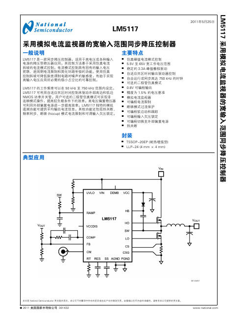
30143201 LM5117 采用模拟电流监视器的宽输入范围同步降压控制器美国国家半导体公司 301432本文是 National Semiconductor 英文版的译文,本公司不对翻译中存在的差异或由此产生的错误负责。
如需确认任何内容的准确性,请参考本公司提供的英文版。
连线图30143279顶视图20 引脚 TSSOP EP30143202顶视图LLP-24 (4 mm × 4 mm)订购信息订购号封装类型NSC 封装图纸供货方式特点LM5117PMH TSSOP-20EP MXA20A 每排 73 只LM5117PMHE TSSOP-20EP MXA20A 250 只带装和卷装LM5117PMHX TSSOP-20EP MXA20A 2500 只带装和卷装LM5117PSQ LLP-24SQA24A 1000 只带装和卷装LM5117PSQE LLP-24SQA24A 250 只带装和卷装LM5117PSQXLLP-24SQA24A4500 只带装和卷装 2L M 5117引脚描述TSSOP 引脚LLP引脚名称说明124UVLO欠压锁定编程引脚。
当 UVLO 引脚低于 0.4V 时,稳压器处于关断模式,所有功能被禁用。
如果UVLO 引脚电压高于 0.4V 并低于 1.25V,稳压器随 VCC 稳压器运行而处于待机模式,此时 SS 引脚接地,且 HO 和 LO 输出端不会切换。
如果 UVLO 引脚电压高于 1.25V,SS 引脚允许电压上升,同时脉宽调制栅极驱动信号传递至 HO 和 LO 引脚。
当 UVLO 超过 1.25V,且流经外部 UVLO 电阻时,20 µA 灌电流被激活以提供迟滞。
21DEMB可选逻辑输入可以在低态时启用二极管仿真。
在二极管仿真模式下,在检测到反向电流流过 (电流从输出到地流经低边 NMOS) 后,低边 NMOS 在 PWM 周期的其余部分被锁断。
LM358中文数据手册范本
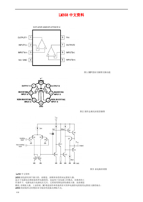
LM358中文资料图1 DIP塑封引脚图引脚功能图2 圆形金属壳封装管脚图图3 部电路原理图lm358中文资料LM358部包括有两个独立的、高增益、部频率补偿的双运算放大器,适合于电源电压围很宽的单电源使用,也适用于双电源工作模式,在推荐的工作条件下,电源电流与电源电压无关。
它的使用围包括传感放大器、直流增益模组,音频放大器、工业控制、DC增益部件和其他所有可用单电源供电的使用运算放大器的场合。
LM358的封装形式有塑封8引线双列直插式和贴片式。
特性(Features):*部频率补偿。
*直流电压增益高(约100dB) 。
*单位增益频带宽(约1MHz) 。
*电源电压围宽:单电源(3—30V);双电源(±1.5一±15V) 。
*低功耗电流,适合于电池供电。
*低输入偏流。
*低输入失调电压和失调电流。
*共模输入电压围宽,包括接地。
*差模输入电压围宽,等于电源电压围。
*输出电压摆幅大(0至Vcc-1.5V) 。
参数输入偏置电流45 nA输入失调电流50 nA输入失调电压2.9mV输入共模电压最大值VCC~1.5 V共模抑制比80dB电源抑制比100dBLM358应用电路图:图4 直流耦合低通RC有源滤波器图5 LED驱动器图6 TTL驱动电路图7 RC有源带通滤波器图8 Squarewave振荡器图9 滞后比较器图10 带通有源滤波器图11 灯驱动程序图12 电流监视器图13 低漂移峰值检测器图14 电压跟随器图15 功率放大器外围电路图16 电压控制振荡器VCO图17 固定电流源图18 脉冲发生器图19 交流耦合反相放大器图20 交流耦合非反相放大器图21 可调增益仪表放大器图22 直流放大器图23脉冲发生器图24 桥式电流放大器图25 引用差分输入信号图26 直流差动放大器。
lm7812中文资料_数据手册_参数
LM78XX
LINEAR INTEGRATED CIRCUIT
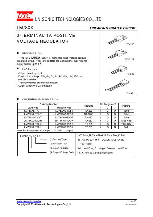
3-TERMINAL 1A POSITIVE VOLTAGE REGULATOR
1
TO-220
DESCRIPTION
The UTC LM78XX family is monolithic fixed voltage regulator integrated circuit. They are suitable for applications that required supply current up to 1 A.
2.0
V
70 mV
35 mV
70 mV
70 mV
8.0 mA
1.0 mA
0.5 mA
50
μV
-0.8
mV/°C
59 75
dB
1.7
A
UNISONIC TECHNOLOGIES CO., LTD
5 of 13
QW-R101-006.U
LM78XX
LINEAR INTEGRATED CIRCUIT
PARAMETER
SYMBOL
RATING
UNIT
Input voltage
VOUT=5~18V VOUT=24V
VIN
35
V
40
V
Output Current Power Dissipation
IOUT
1
A
PD
Internally Limited
W
Operating Junction Temperature Storage Temperature
LM258中文资料_数据手册_参数

LM158, LM158A, LM258, LM258A LM358, LM358A, LM2904, LM2904V
SLOS068T – JUNE 1976 – REVISED APRIL 2015
Table of Contents
1 Features .................................................................. 1 2 Applications ........................................................... 1 3 Description ............................................................. 1 4 Revision History..................................................... 2 5 Pin Configuration and Functions ......................... 3 6 Specifications......................................................... 4
Brushless DC, High-Voltage, Low-Voltage, Permanent Magnet, and Stepper Motor • Oscilloscopes • TV: LCD and Digital • Temperature Sensors or Controllers Using Modbus • Weigh Scales
Device Information(1)
LM5118中文数据手册

EN输入低阈值 EN输入高门槛 EN输入偏置电流 EN输入偏置电流 EN输入偏置电流
UVLO待机阈值 UVLO阈值迟滞 UVLO上拉电流源 UVLO拉向下R
DS(ON)
SS电流源 SS到FB偏移 SS输出低电压
条件
VCCX = 0V VCCX = 5V EN = 0V
95
115
135
µA
65
80
95
µA
245
µA
0.095 0.14
0.23
V
0.25
V
16
ns
14
ns
2.2
A
2.7
A
0.1
0.135
0.21
V
0.25
V
14
ns
12
ns
2.2
V
3.5
V
3
V
69
75
80
%
165
°C
25
°C
40
°C/W
4
°C/W
5
LM5118 Note 1: Absolute Maximum Ratings are limits beyond which damage to the device may occur. Operating Ratings indicate conditions for which the device is intended to be functional, but does not guarantee specific performance limits. For guaranteed specifications and test conditions see the Electrical Characteristics.
LM334中文资料_数据手册_参数
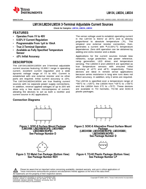
Absolute Maximum Ratings(1)(2)
V+ to V− Forward Voltage
V+ to V− Reverse Voltage R Pin to V− Voltage Set Current Power Dissipation ESD Susceptibility(3) Operating Temperature Range(4)
LM134, LM234, LM334
SNVS746E – MARCH 2000 – REVISED MAY 2013
Electrical Characteristics(1)
Parameter
Conditions
Set Current Error, V+=2.5V(2)
Ratio of Set Current to Bias Current
1mA < ISET ≤ 5mA
Temperature Dependence of Set Current(3) Effective Shunt Capacitance
(LM334SM; LM334SM/NOPB; LM334SMX; LM334SMX/NOPB)
See Petal Can Package (Bottom View) See Package Number NDV
Figure 4. TO-92 Plastic Package (Bottom View) See Package Number LP
LM25119中文数据手册

CS2 CSG2 PGND2 LO2 VCC2 SW2 HO2 HB2
电流检测放大器输入。连接至通道 2 电流检测电阻的高边。
至电流检测电阻的开尔文 (Kelvin) 接地连线。直接连接至通道 2 电流检测电阻的低边。
低边 MOSFET 栅极驱动器的电源接地返回引脚。直接连接至通道 2 电流检测电阻的低边。
VIN = 4.5V, 无外部负载 VCC = 0V VCCDIS 上升 VCCDIS = 0V 正向 VCC
UVLO 上升 UVLO = 1.4V
用于自举栅极驱动的高边驱动器电源。连接至通道 2 外部自举二极管的阴极和自举电容。自举电容 提供电流为高边 MOSFE欠压锁定编程引脚。当 UVLO 引脚低于 0.4V 时,稳压器处于关断模式,所有功能被关闭。 如果 UVLO 引脚的电压大于 0.4V 并低于 1.25V,稳压器随 VCC 稳压器运行而处于待机模式,此时 SS 引脚接地,且 HO 和 LO 输出端不会切换。如果 UVLO 引脚电压高于 1.25V,SS 引脚允许电压 上升,同时脉宽调制栅极驱动信号传递至 HO 和 LO 引脚。当 UVLO 超过 1.25V,且流经外部 UVLO 电阻时,20 µA 灌电流源被激活以提供迟滞。
即可同步至外部时钟。
14
RES
外部电容器重启定时器引脚可配置打嗝模式电流限制。在打嗝模式下自动重启前,RES 引脚上的
电容器决定控制器处于关闭状态的时间。两个稳压器通道独立运行。一个通道可能会在正常模式下
运行,而另一个处在打嗝模式过载保护状态。当通道经过了逐周期电流限制的 256 个连续 PWM
周期时,打嗝模式开始。在此之后,10 µA 灌电流源对 RES 引脚电容充电至 1.25V 阈值,重启过
LM5118中文数据手册

(注1)
-0.3V至76V -0.3 15V -0.3 15V
-0.3至HB +0.3 V -4V至76V
-0.3V到+0.3 V
RAMP,SS,COMP,FB,同步,RT到GND ESD额定值 HBM(注2)
存储温度范围
结温
-0.3 7V
2千伏 -55°C至+150°C
+150°C
工作额定值
VIN(注4) VCC,VCCX
斜坡电流1 斜坡电流2 斜坡电流3 VOUT偏置电流
LO低态输出电压 LO高态输出电压
IOHL IOLL 高方(HO)栅极驱动器 VOLH VOHH
LO上升时间 LO下降时间 卢峰源电流 LO峰值灌电流
何低电平输出电压 何高态输出电压
IOHH IOLH
BUCK-BOOST特性
热 T SD
θJA θJC
集成高侧和低侧栅极驱动器 可编程软启动时间 极低的关断电流
仿真电流斜坡.模拟电流模式控制降低了脉冲宽度调制电路的噪声 ■ 使能输入高带宽误差放大器
敏感度,允许必要在高输入电压应用的非常小的占空比的可靠控制.其 ■ 1.5%反馈参考精度
他保护功能包括电流限制,热关断和使能输入.
■ 热关断
包
采用TSSOP-20EP(裸焊盘)
95
115
135
µA
65
80
95
µA
245
µA
0.095 0.14
0.23
V
0.25
V
16
ns
14
ns
2.2
A
2.7
A
0.1
0.135
0.21
V
LM3150(中文)

LM3150
符号
参数
规例及以上电压比较器
V FB V FB-OV
IFB 升压二极管
在调节反馈电压 Feedback过电压阈值 电流反馈偏置
正向电压 Vf
热特性 T SD
热关断 热关断迟滞
θ
JA
结到环境
θ
JC
结到管壳
条件
VSS > 0.6V
IBST = 2 mH IBST = 30 mA
瑞星 下降 4层JEDEC的印刷电路 局,9 Vias,没有空气流动 2层JEDEC的印刷电路 董事会.没有空气流动 没有空气流动
6.25
V
mV
mA
5.40
V
mV
µs
5
mA
55
µA
GATE Drive IQ-BST
R DS-HG-Pull-Up R DS-HG-Pull-Down
R DS-LG-Pull-Up R DS-LG-Pull-Down 软启动
ISS ISS-DIS 电流限制
ILIM-TH 开/关定时器
BOOST引 脚泄漏 HG车道Pull–Up导通电阻 HG车道Pull–Down导通电阻 LG车道Pull–Up导通电阻 LG车道Pull–Down导通电阻
在固定导通时间(COT)规例的架构使
快速瞬态响应,无需环路方赔偿,
tion,从而降低了外部元件数量,并降低
设计复杂性.
如热关断故障保护功能,欠 分离电压,过电压保护,短路保护, tion,电流限制,输出电压pre-bias允许启动 一个稳定可靠的解决方案.
该LM3150的SIMPLE SWITCHER
3.4
Ω
3.4
Ω
lm2596中文资料_数据手册_参数
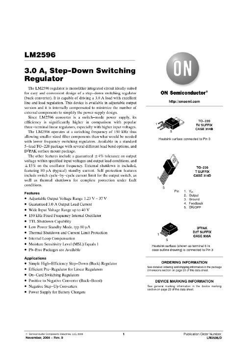
·Regulatorsfrequency卡片上的切换。包括外部关闭,·正到负Convertertypically 80μa 待机电流。自我保护特性包括输出开关的两级频率减少电流限制和完全保护故障状 态下的过热关闭。(1)(1)__专利号5382918。典型应用(固定输出电压版本)请注意,关 于lm2596德州仪器半导体产品和免责lm2596声明的可用性、标准保证和关键应用的 一个重要通知出现在本数据表的末尾。简单切换器是德州仪器的注册商标。所有其 他商标都是其各自所有者的财产。生产数据信息是当前出版日期。版权©1999 - 2013 年,德州仪器IncorporatedProducts符合规格/ TexasInstruments标准保修条款。生产加工 不连接DiagramsFigure 1。5根引线弯曲交错,如图2所示。5-Lead DDPAK/TO-263 (S) PackageThrough Hole TO-220 (T) PackageSee Package Number KTT0005BSee Package Number NDH0005DThese devices have limited内置ESD protection。在储存或处理过程 中,应将引线短接在一起,或将设备置于导电泡沫中,以防止对MOS门的静电损 坏。绝对最大额定参数(1)(2)最大供应Voltage45VON /关销输入电压 0.3 V≤≤+ 25 vfeedback销电压0.3 V≤≤25 + voutput对地电压(稳态) 1 vpower DissipationInternally limitedStorage温度范围 65°C + 150°CESD SusceptibilityHuman身体模型(3)2 kVLead TemperatureDDPAK / - 263 PackageVapor阶段(60秒。)+ 215°CInfrared(10秒)+ 245° 首席技术官- 220包(焊接,10秒)+ 260°CMaximum结温+ 150°C(1)绝对最大额定参数 表明超过这个限制可能发生损坏设备。操作额定值指示设备功能的条件,但不保证 特定的性能限制。(2)如果需lm2596要军用/航空航天专用设备,请与德州仪器销售 办公室/分销商联系,了解其可用性和规格。操作ConditionsTemperature范围 40° C≤TJ≤+ 125°CSupply Voltage4.5V 40 v2submit文档FeedbackCopyright©1999 - 2013年, 德州仪器IncorporatedProduct文件夹链接:LM259图2显示了计时器2自动计数 whenDCEN = 0。在此模式下,bitEXEN2在T2CON中选择两个选项。如果EXEN2 = 0,计时器2计数到0ffh,然后在溢出时设置TF2位。溢出还会导致计时器寄存器被重 新加载,其中包含RCAP2H和RCAP2L中的16位值。捕获ModeRCAP2H和RCAP2L中 的inTimer的值是由软件预先设lm2596定的。如果EXEN2 = 1,那么16位的重载可以 通过溢出或在externalinput T2EX中通过1到0的转换触发。这个转换还设置了EXF2 位。tf2和EXF2位都可以在启用时生成中断。设置DCEN位使定时器2可以向上或向下 计数,如图3所示。在这种模式下,T2EX pin控制了计数的方向。T2EX的逻辑1使计 时器2计数。计时器将在0ffh溢出并设置tf2位。这种溢出还会导致16位值inRCAP2H 和RCAP2L分别被重新加载lm2596到计时器寄存器TH2和TL2中。T2EX的逻辑0使定 时器2倒数。当TH2和TL2等于存储在inRCAP2H和RCAP2L中的值 时,timerunderflows。下流设置TF2位并将0ffh重新加载到计时器寄存器中。EXF2位 可在计时器2溢出或溢出时切换,可lm2596以用作第17位的分辨率。在此操作模式 中,EXF2不标记中断
LM311中文资料_数据手册_参数

D Fast Response Times D Strobe Capability D Maximum Input Bias Current . . . 300 nA D Maximum Input Offset Current . . . 70 nA
LM311D LM311DR LM311PSR
LM311 L311
TSSOP (PW)
Reel of 150 Tube of 2000
LM311PW LM311PWR
L311
PDIP (P)
Tube of 50
LM211P
LM211P
–40°C to 85°C
3 mV
SOIC (D)
Tube of 75 Reel of 2500
SLCS007H – SEPTEMBER 1973 – REVISED AUGUST 2003
D Can Operate From Single 5-V Supply D Available in Q-Temp Automotive
– High-Reliability Automotive Applications – Configuration Control/Print Support – Qualification to Automotive Standards
LM111 . . . JG PACKAGE LM211 . . . D, P, OR PW PACKAGE LM311 . . . D, P, PS, OR PW PACKAGE
(TOP VIEW)
EMIT OUT 1 IN+ 2 IN– 3
lm1117-3.3中文资料_数据手册_参数

LM358中文数据手册
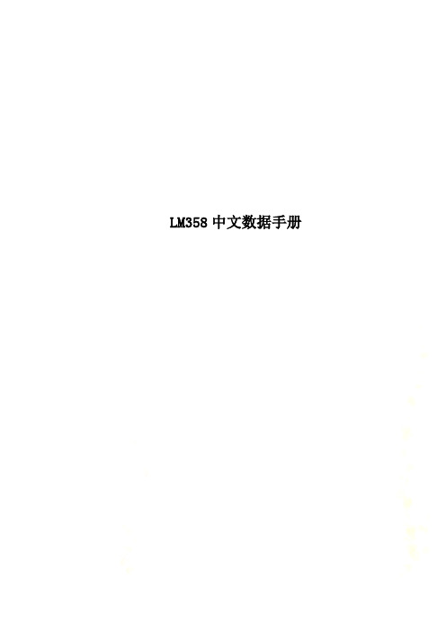
LM358中文数据手册LM358中文资料图1 DIP塑封引脚图引脚功能图2 圆形金属壳封装管脚图图3 内部电路原理图lm358中文资料LM358内部包括有两个独立的、高增益、内部频率补偿的双运算放大器,适合于电源电压范围很宽的单电源使用,也适用于双电源工作模式,在推荐的工作条件下,电源电流与电源电压无关。
它的使用范围包括传感放大器、直流增益模组,音频放大器、工业控制、DC增益部件和其他所有可用单电源供电的使用运算放大器的场合。
LM358的封装形式有塑封8引线双列直插式和贴片式。
特性(Features):*内部频率补偿。
*直流电压增益高(约100dB) 。
*单位增益频带宽(约1MHz) 。
*电源电压范围宽:单电源(3—30V);双电源(±1.5一±15V) 。
*低功耗电流,适合于电池供电。
*低输入偏流。
*低输入失调电压和失调电流。
*共模输入电压范围宽,包括接地。
*差模输入电压范围宽,等于电源电压范围。
*输出电压摆幅大(0至Vcc-1.5V) 。
参数输入偏置电流45 nA输入失调电流50 nA输入失调电压2.9mV输入共模电压最大值VCC~1.5 V共模抑制比80dB电源抑制比100dBLM358应用电路图:图4 直流耦合低通RC有源滤波器图5 LED驱动器图6 TTL驱动电路图7 RC 有源带通滤波器图8 Squarewave振荡器图9 滞后比较器图10 带通有源滤波器图11 灯驱动程序图12 电流监视器图13 低漂移峰值检测器图14 电压跟随器图15 功率放大器外围电路图16 电压控制振荡器VCO图17 固定电流源图18 脉冲发生器图19 交流耦合反相放大器图20 交流耦合非反相放大器图21 可调增益仪表放大器图22 直流放大器图23脉冲发生器图24 桥式电流放大器图25 引用差分输入信号图26 直流差动放大器。
LM331中文资料_数据手册_参数
Sample & Buy
Technical Documents
Tools & Software
ቤተ መጻሕፍቲ ባይዱ
Support & Community
LM231, LM331
SNOSBI2C – JUNE 1999 – REVISED SEPTEMBER 2015
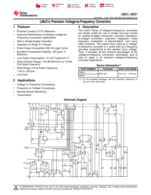
LMx31x Precision Voltage-to-Frequency Converters
1 Hz to 100 kHz • Low-Cost
2 Applications
• Voltage to Frequency Conversions • Frequency to Voltage Conversions • Remote-Sensor Monitoring • Tachometers
LM231, LM331
SNOSBI2C – JUNE 1999 – REVISED SEPTEMBER 2015
Table of Contents
1 Features .................................................................. 1 2 Applications ........................................................... 1 3 Description ............................................................. 1 4 Revision History..................................................... 2 5 Description continued ........................................... 3 6 Pin Configuration and Functions ......................... 4 7 Specifications......................................................... 4
LM337中文资料_数据手册_参数

Normally, only a single 1-µF solid tantalum output capacitor is required unless the device is situated more than 6 inches from the input filter capacitors, in which case an input bypass is required. A larger output capacitor can be added to improve transient response. The adjustment pin can be bypassed to achieve very high ripple rejection ratios, which are difficult to achieve with standard 3-pin regulators.
Product Folder
Sample & Buy
Technical Documents
Tools & Software
Support & Community
LM337L
SNVS780E – MAY 1998 – REVISED DECEMBER 2016
LM337L 3-Terminal Adjustable Regulator
1
SOIC
Copyright © 2016, Texas Instruments Incorporated
1
An IMPORTANT NOTICE at the end of this data sheet addresses availability, warranty, changes, use in safety-critical applications, intellectual property matters and other important disclaimers. PRODUCTION DATA.
LM2903中文资料_数据手册_参数

LM337中文资料_数据手册_参数

LM337中⽂资料_数据⼿册_参数-V IN Copyright ? 2016, Texas Instruments Incorporated TO-92SOICPin 1. Output2.Adjustment3. Input3121ProductFolder Sample &Buy TechnicalDocuments Tools &Software Support &CommunityLM337LSNVS780E –MAY 1998–REVISED DECEMBER 2016LM337L 3-Terminal Adjustable Regulator1FeaturesAdjustable Output Down to 1.2V ?Ensured 100-mA Output Current ?Line Regulation Typically 0.01%/V ?Load Regulation Typically 0.1%?Current Limit Constant With Temperature ?Eliminates the Need to Stock Many Voltages ?Standard 3-Pin Transistor Package ?80-dB Ripple Rejection ?Output is Short Circuit Protected 2Applications ?Industrial Power Supplies ?Factory Automation Systems ?Building Automation Systems ?PLC Systems ?Instrumentation ? IGBT Drive Negative Gate Supplies ?Networking ?Set-Top Boxes 3Description The LM337L is an adjustable 3-pin negative voltage regulator capable of supplying 100mA over a –1.2-V to –37-V output range.The LM337L is easy to use and requires only two external resistors to set the output voltage.Both line and load regulation are better than standard fixed regulators.The LM337L is packaged in a standard,easy-to-use TO-92transistor package.In addition to higher performance than fixedregulators,the LM337L offers full overload protection.Included on the chip are current limit,thermaloverload protection,and safe area protection.Alloverload protection circuitry remains fully functionaleven if the adjustment pin is disconnected.Normally,only a single 1-µF solid tantalum output capacitor is required unless the device is situated more than 6inches from the input filter capacitors,in which case an input bypass is required.A larger output capacitor can be added to improve transient response.The adjustment pin can be bypassed to achieve very high ripple rejection ratios,which are difficult to achieve with standard 3-pin regulators.Besides replacing fixed regulators,the LM337L is useful in a wide variety of other applications.Because the regulator is floating and monitors only the input-to-output differentialvoltage,supplies of severalhundred volts can be regulated as long as themaximum input-to-output differential is not exceeded.The LM337L makes a simple adjustable switchingregulator,a programmable output regulator,or byconnecting a fixed resistor between the adjustmentand output,the LM337L can be used as a precisioncurrent regulator.Supplies with electronic shutdowncan be achieved by clamping the adjustment pin toground,which programs the output to 1.2V,wheremost loads draw little current.The LM337L is available in a standard TO-92transistor package and a standard SO-8surfacemount package.The LM337L is rated for operationover a –25°C to 125°C range.For applications requiring output current in excess of0.5A and 1.5A,The LM137series may be suitable.For the positive complement,the LM117and LM317Lseries are options.Device Information (1)PART NUMBERPACKAGE BODY SIZE (NOM)LM337L SOIC (8)3.91mm ×4.90mm TO-92(3) 4.30mm ×4.30mm (1)For all available packages,see the orderable addendum at the end of the data sheet.1.2-V to 25-V Adjustable Regulator LM337L Available PackagesLM337LSNVS780E–MAY1998–REVISED /doc/c345595427fff705cc1755270722192e453658bd.htmlTable of Contents1Features (1)2Applications (1)3Description (1)4Revision History (2)5Pin Configuration and Functions (3)6Specifications (3)6.1Absolute Maximum Ratings (3)6.2ESD Ratings (3)6.3Recommended Operating Conditions (3)6.4Thermal Information (4)6.5Electrical Characteristics (4)6.6Typical Characteristics (5)7Detailed Description (6)7.1Overview (6)7.2Functional Block Diagram (6)7.3Feature Description (6)7.4Device Functional Modes (6)8Application and Implementation (8)8.1Application Information (8)8.2Typical Applications (8)9Power Supply Recommendations (10)10Layout (10)10.1Layout Guidelines (10)10.2Layout Example (10)11Device and Documentation Support (11)11.1Documentation Support (11)11.2Receiving Notification of Documentation Updates1111.3Community Resources (11)11.4Trademarks (11)11.5Electrostatic Discharge Caution (11)11.6Glossary (11)12Mechanical,Packaging,and OrderableInformation (11)4Revision HistoryNOTE:Page numbers for previous revisions may differ from page numbers in the current version.Changes from Revision D(May2013)to Revision E Page ?Added Applications section,Device Information table,Pin Configuration and Functions section,ESD Ratings table, Recommended Operating Conditions table,Typical Characteristics section,Detailed Description section,Application and Implementation section,Power Supply Recommendations section,Layout section,Device and Documentation Support section,and Mechanical,Packaging,and Orderable Information section (1)Deleted DSBGA Package references throughout the data sheet (1)Deleted soldering information rows from Absolute Maximum Ratings table (3)Added Thermal Information table (4)Changed RθJA values for D(SOIC)package From:180To:111.3and for LP(TO-92)package From:160To:156.9 (4)Changes from Revision C(May2013)to Revision D Page ?Changed layout of National Semiconductor Data Sheet to TI format (1)LM337L/doc/c345595427fff705cc1755270722192e453658bd.html SNVS780E –MAY 1998–REVISED DECEMBER 20165Pin Configuration and FunctionsD Package8-Pin SOICTop View LP Package 3-Pin TO-92Bottom ViewPin FunctionsPINI/O DESCRIPTIONNAMETO-92SOIC ADJ14—Adjust pin NC—5,8—No connection VIN32,3,6,7Input Input voltage pin for the regulator VOUT 21Output Output voltage pin for the regulator (1)Stresses beyond those listed under Absolute Maximum Ratings may cause permanent damage to the device.These are stress ratings only,which do not imply functional operation of the device at these or any other conditions beyond those indicated under Recommended Operating Conditions .Exposure to absolute-maximum-rated conditions for extended periods may affect device reliability.(2)If Military/Aerospace specified devices are required,please contact the Texas Instruments Sales Office/Distributors for availability andspecifications.6Specifications6.1Absolute Maximum RatingsSee (1)(2)MINMAX UNIT Input-output voltage differential40V Power dissipationInternally Limited Storage temperature,T stg–55150°C (1)JEDEC document JEP155states that 500-V HBM allows safe manufacturing with a standard ESD control process.Pins listed as ±1500V may actually have higher performance.(2)Human-body model,1.5k ?in series with 100pF.6.2ESD RatingsVALUEUNIT V (ESD)Electrostatic discharge Human-body model (HBM),per ANSI/ESDA/JEDEC JS-001(1)(2)±1500V 6.3Recommended Operating Conditionsover operating free-air temperature range (unless otherwise noted)MINMAX UNIT Operating junction temperature –25125°CLM337LSNVS780E –MAY 1998–REVISED DECEMBER /doc/c345595427fff705cc1755270722192e453658bd.html(1)For more information about traditional and new thermal metrics,see the Semiconductor and IC Package Thermal Metrics applicationreport.6.4Thermal InformationTHERMAL METRIC(1)LM337LUNIT D (SOIC)LP (TO-92)8PINS 3PINS R θJAJunction-to-ambient thermal resistance 111.3156.9°C/W R θJC(top)Junction-to-case (top)thermal resistance 56.180.2°C/W R θJBJunction-to-board thermal resistance 51.9—°C/W ψJTJunction-to-top characterization parameter 10.624.7°C/W ψJBJunction-to-board characterization parameter 51.3136.2°C/W (1)Unless otherwise specified,these specifications apply –25°C ≤T J ≤125°C for the LM337L;|V IN –V OUT |=5V and I OUT =40mA.Although power dissipation is internally limited,these specifications are applicable for power dissipations up to 625mW.I MAX is 100mA.(2)Regulation is measured at constant junction temperature,using pulse testing with a low duty cycle.Changes in output voltage due toheating effects are covered under the specification for thermal regulation.6.5Electrical Characteristics (1)PARAMETERTEST CONDITIONS MIN TYP MAX UNIT Line regulation (2)T A =25°C,3V ≤|V IN –V OUT |≤40V 0.010.04%/V Load regulation (2)T A =25°C,5mA ≤I OUT ≤I MAX 0.1%0.5%Thermal regulationT A =25°C,10-ms Pulse 0.040.2%/W Adjustment pin current50100µA Adjustment pin current change5mA ≤I L ≤100mA,3V ≤|V IN –V OUT |≤40V 0.25µA Reference voltage3V ≤|V IN –V OUT |≤40V,10mA ≤I OUT ≤100mA,P ≤625mW 1.2 1.25 1.3V Line regulation (2)3V ≤|V IN –V OUT |≤40V 0.020.07%/V Load regulation (2)5mA ≤I OUT ≤100mA 0.3% 1.5%Temperature stabilityT MIN ≤T j ≤T MAX 0.65%Minimum load current|V IN –V OUT |≤40V 3.55mA 3V ≤|V IN –V OUT |≤15V 2.2 3.5mA Current limit3V ≤|V IN –V OUT |≤13V 100200320mA |V IN –V OUT |=40V 2550120mA RMS output noise,%of V OUTT A =25°C,10Hz ≤f ≤10kHz 0.003%Ripple rejection ratioV OUT =–10V,F =120Hz,C ADJ =065dB C ADJ =10µF 6680dB Long-term stabilityT A =125°C 0.3%1%LM337L /doc/c345595427fff705cc1755270722192e453658bd.html SNVS780E–MAY1998–REVISED DECEMBER20166.6Typical CharacteristicsFigure3.Line Transient Response Figure4.Load Transient ResponseINPUTOUTPUTADJUSTCopyright ? 2016,Texas Instruments IncorporatedLM337LSNVS780E –MAY 1998–REVISED DECEMBER /doc/c345595427fff705cc1755270722192e453658bd.html7Detailed Description7.1OverviewThe LM337L devices are adjustable 3-terminal negative-voltage regulators capable of supplying 100mA over anoutput voltage range of –1.2V to –37V.They are exceptionally easy to use,requiring only two external resistorsto set the output voltage and one output capacitor for frequency compensation.In addition,LM337L offers fulloverload protection.Included on the chip are current limit,thermal overload protection and safe area protection.All overload protection circuitry remains fully functional even if the adjustment terminal is disconnected.TheLMx37devices serve a wide variety of applications,including local on-card regulation,programmable output-voltage regulation,and precision current regulation.7.2Functional Block Diagram7.3Feature Description7.3.1Output Voltage AdjustmentThe Adjustment (ADJ)pin serves as a voltage adjustment reference for the output.The ADJ pin can be attachedto a resistor divider circuit to adjust the output voltage level.The reference voltage VADJ will typically be 1.25Vhigher than VO.7.4Device Functional Modes7.4.1Protection DiodesWhen external capacitors are used with any IC regulator,it is sometimes necessary to add protection diodes toprevent the capacitors from discharging through low current points into the regulator.Most 10-µF capacitors havelow enough internal series resistance to deliver 20-A spikes when shorted.Although the surge is short,there isenough energy to damage parts of the IC.When an output capacitor is connected to a negative output regulatorand the input is shorted,the output capacitor pulls current out of the output of the regulator.The current dependson the value of the capacitor,the output voltage of the regulator,and the rate at which VIN is shorted to ground.The bypass capacitor on the adjustment terminal can discharge through a low current junction.Discharge occurswhen either the input,or the output,is shorted.Figure 15shows the placement of the protection diodes.LM337L /doc/c345595427fff705cc1755270722192e453658bd.html SNVS780E–MAY1998–REVISED DECEMBER2016 Device Functional Modes(continued)When CL is larger than20µF,D1protects the LM337L in case the input supply is shorted.When C2is larger than10µF and?VOUT is larger than?25V,D2protects the LM337L in case the output is shorted.Figure5.Regulator With Protection DiodesOUT R2V 1.25V 1240§· ¨?:?1-V IN Copyright ? 2016, Texas Instruments IncorporatedLM337LSNVS780E –MAY 1998–REVISED DECEMBER /doc/c345595427fff705cc1755270722192e453658bd.html8Application and ImplementationNOTEInformation in the following applications sections is not part of the TI componentspecification,and TI does not warrant its accuracy or completeness.TI’s customers areresponsible for determining suitability of components for their purposes.Customers shouldvalidate and test their design implementation to confirm system functionality.8.1Application InformationThe LM337L is a negative output linear regulator with high accuracy and a wide temperature range.An outputcapacitor can be added to further improve transient response,and the ADJ pin can be bypassed to achieve veryhigh ripple-rejection ratios.The device's functionality can be utilized in many different applications that requirenegative voltage supplies,such as bipolar amplifiers,operational amplifiers,and constant current regulators.8.2Typical Applications8.2.1 1.2-V to 25-V Adjustable RegulatorFull output current not available at high input-output voltagesC1=1-µF solid tantalum or 10-µF aluminum electrolytic required for stability*C2=1-µF solid tantalum is required only if regulator is more than 4″from power supply filter capacitorFigure 6. 1.2-V to 25-V Adjustable Regulator Diagram8.2.1.1Design RequirementsThe device component count is very minimal,employing two resistors as part of a voltage divider circuit and anoutput capacitor for load regulation.An input capacitor is needed if the device is more than 4in.from the filtercapacitors.8.2.1.2Detailed Design ProcedureThe output voltage is set based on the selection of the two resistors (R1and R2)as shown in Equation 1.(1)-22 VCopyright ? 2016, Texas Instruments Incorporated LM337L/doc/c345595427fff705cc1755270722192e453658bd.html SNVS780E–MAY1998–REVISED DECEMBER2016 Typical Applications(continued)8.2.1.3Application CurveFigure7.Dropout Voltage across Load Current at25°C(?Vout<100mV8.2.2Regulator With Trimmable Output VoltageFigure8.Regulator with Trimmable Output Voltage Diagram8.2.2.1Design RequirementsThis design uses five resistors with two being used for a voltage divider circuit and the other three used for trimming the output voltage.The benefit is lower cost as compared to using a trim pot.An output capacitor is needed to improve load regulation.8.2.2.2Detailed Design ProcedureThis design will trim the output voltage to within1%of–22V.The parallel combination of R1,R3,R4and R5 serve as the bottom resistance and R2as the top resistance in the voltage divider that sets the output voltage. Trim Procedure:If V OUT is–23.08V or larger,do not use R3,otherwise leave it in.Then if V OUT is–22.47V or bigger,do not use R4,otherwise leave it in.Then if V OUT is–22.16V or bigger,do not use R5,otherwise leave it in.This will trim the output to well within1%of–22V DC,without any of the expense or trouble of a trim pot(see LB-46).This technique can be used at any output voltage level.LM337LSNVS780E–MAY1998–REVISED /doc/c345595427fff705cc1755270722192e453658bd.html 9Power Supply RecommendationsThe input supply to the LM337L must be kept at a voltage level such that its maximum input to output differential voltage rating is not exceeded.The minimum dropout voltage must also be met with extra headroom when possible to keep the LM337L in regulation.TI recommends an input capacitor,especially when the input pin is placed more than4in.away from the power-supply filter capacitor.10Layout10.1Layout GuidelinesSome layout guidelines must be followed to ensure proper regulation of the output voltage with minimum noise. Traces carrying the load current must be wide to reduce the amount of parasitic trace inductance and the feedback loop from VOUT to ADJ must be kept as short as possible.To improve PSRR,a bypass capacitor can be placed at the ADJ pin and must be placed as close as possible to the IC.In cases when VIN shorts to ground, an external diode must be placed from VIN to VOUT to divert the surge current into the output capacitor and protect the IC.Similarly,in cases when a large bypass capacitor is placed at the ADJ pin and VOUT shorts to ground,an external diode must be placed from VOUT to ADJ to provide a path for the bypass capacitor to discharge.These diodes must be placed close to the corresponding IC pins to increase their effectiveness.10.2Layout ExampleFigure9.LM337L Layout ExampleLM337L /doc/c345595427fff705cc1755270722192e453658bd.html SNVS780E–MAY1998–REVISED DECEMBER201611Device and Documentation Support11.1Documentation Support11.1.1Related DocumentationFor related documentation see the following:LM317L-N3-Terminal Adjustable Regulator(SNOSBW2)LM117,LM317-N Wide Temperature Three-Pin Adjustable Regulator(SNVS774)LM317L-N3-Terminal Adjustable Regulator(SNVS775)11.2Receiving Notification of Documentation UpdatesTo receive notification of documentation updates,navigate to the device product folder on /doc/c345595427fff705cc1755270722192e453658bd.html .In the upper right corner,click on Alert me to register and receive a weekly digest of any product information that has changed.For change details,review the revision history included in any revised document.11.3Community ResourcesThe following links connect to TI community resources.Linked contents are provided"AS IS"by the respective contributors.They do not constitute TI specifications and do not necessarily reflect TI's views;see TI's Terms of Use.TI E2E?Online Community TI's Engineer-to-Engineer(E2E)Community.Created to foster collaboration among engineers.At/doc/c345595427fff705cc1755270722192e453658bd.html ,you can ask questions,share knowledge,explore ideas and helpsolve problems with fellow engineers.Design Support TI's Design Support Quickly find helpful E2E forums along with design support tools and contact information for technical support.11.4TrademarksE2E is a trademark of Texas Instruments.All other trademarks are the property of their respective owners.11.5Electrostatic Discharge CautionThis integrated circuit can be damaged by ESD.Texas Instruments recommends that all integrated circuits be handled with appropriate precautions.Failure to observe proper handling and installation procedures can cause damage.ESD damage can range from subtle performance degradation to complete device failure.Precision integrated circuits may be more susceptible to damage because very small parametric changes could cause the device not to meet its published specifications. 11.6GlossarySLYZ022—TI Glossary.This glossary lists and explains terms,acronyms,and definitions.12Mechanical,Packaging,and Orderable InformationThe following pages include mechanical,packaging,and orderable information.This information is the most current data available for the designated devices.This data is subject to change without notice and revision of this document.For browser-based versions of this data sheet,refer to the left-hand navigation.PACKAGING INFORMATION(1) The marketing status values are defined as follows:ACTIVE: Product device recommended for new designs.LIFEBUY: TI has announced that the device will be discontinued, and a lifetime-buy period is in effect.NRND: Not recommended for new designs. Device is in production to support existing customers, but TI does not recommend using this part in a new design.PREVIEW: Device has been announced but is not in production. Samples may or may not be available.OBSOLETE: TI has discontinued the production of the device.(2) Eco Plan - The planned eco-friendly classification: Pb-Free (RoHS), Pb-Free (RoHS Exempt), or Green (RoHS & no Sb/Br) - please check/doc/c345595427fff705cc1755270722192e453658bd.html /productcontent for the latest availability information and additional product content details.TBD: The Pb-Free/Green conversion plan has not been defined.Pb-Free (RoHS): TI's terms "Lead-Free" or "Pb-Free" mean semiconductor products that are compatible with the current RoHS requirements for all 6 substances, including the requirement that lead not exceed 0.1% by weight in homogeneous materials. Where designed to be soldered at high temperatures, TI Pb-Free products are suitable for use in specified lead-free processes.Pb-Free (RoHS Exempt): This component has a RoHS exemption for either 1) lead-based flip-chip solder bumps used between the die and package, or 2) lead-based die adhesive used between the die and leadframe. The component is otherwise considered Pb-Free (RoHS compatible) as defined above.Green (RoHS & no Sb/Br): TI defines "Green" to mean Pb-Free (RoHS compatible), and free of Bromine (Br) and Antimony (Sb) based flame retardants (Br or Sb do not exceed 0.1% by weight in homogeneous material)(3) MSL, Peak Temp. - The Moisture Sensitivity Level rating according to the JEDEC industry standard classifications, and peak solder temperature.(4) There may be additional marking, which relates to the logo, the lot trace code information, or the environmental category on the device.(5) Multiple Device Markings will be inside parentheses. Only one Device Marking contained in parentheses and separated by a "~" will appear on a device. If a line is indented then it is a continuation of the previous line and the two combined represent the entire Device Marking for that device.Addendum-Page 1(6) Lead/Ball Finish - Orderable Devices may have multiple material finish options. Finish options are separated by a vertical ruled line. Lead/Ball Finish values may wrap to two lines if the finish value exceeds the maximum column width.Important Information and Disclaimer:The information provided on this page represents TI's knowledge and belief as of the date that it is provided. TI bases its knowledge and belief on information provided by third parties, and makes no representation or warranty as to the accuracy of such information. Efforts are underway to better integrate information from third parties. TI has taken and continues to take reasonable steps to provide representative and accurate information but may not have conducted destructive testing or chemical analysis on incoming materials and chemicals. TI and TI suppliers consider certain information to be proprietary, and thus CAS numbers and other limited information may not be available for release.In no event shall TI's liability arising out of such information exceed the total purchase price of the TI part(s) at issue in this document sold by TI to Customer on an annual basis.Addendum-Page 2TAPE AND REEL INFORMATION*All dimensions are nominal Device Package Type Package DrawingPinsSPQ Reel Diameter (mm)Reel Width W1(mm)A0(mm)B0(mm)K0(mm)P1(mm)W (mm)Pin1Quadrant LM337LMX SOIC D 82500330.012.4 6.5 5.4 2.08.012.0Q1LM337LMX/NOPB SOIC D 82500330.012.4 6.5 5.4 2.08.012.0Q1*All dimensions are nominalDevice Package Type Package Drawing Pins SPQ Length(mm)Width(mm)Height(mm) LM337LMX SOIC D8*******.0367.035.0 LM337LMX/NOPB SOIC D8*******.0367.035.0PACKAGE OUTLINETO-92 - 5.34 mm max height LP0003A TO-92NOTES:1. All linear dimensions are in millimeters. Any dimensions in parenthesis are for reference only. Dimensioning and tolerancing per ASME Y14.5M.2. This drawing is subject to change without notice.3. Lead dimensions are not controlled within this area.4. Reference JEDEC TO-226, variation AA.5. Shipping method:a. Straight lead option available in bulk pack only.b. Formed lead option available in tape and reel or ammo pack.c. Specific products can be offered in limited combinations of shipping medium and lead options.d. Consult product folder for more information on available options.EXAMPLE BOARD LAYOUTTO-92 - 5.34 mm max heightLP0003A TO-92。
LM358引脚的中文数据手册

LM358LM358的封装形式有塑封引线双列直插式、贴片式和圆形金属封装等。
具有低功耗,低噪声的优点LM358内部包括有两个独立的、高增益、内部频率补偿的双运算放大器,适合于电源电压范围很宽的单电源使用,也适用于双电源工作模式,在推荐的工作条件下,电源电流与电源电压无关。
它的使用范围包括传感放大器、直流增益模组,音频放大器、工业控制、DC增益部件和其他所有可用单电源供电的使用运算放大器的场合产品用途:适用于监视器,充电器,汽车功放,小家电控板,无绳电话机,交换机,集线器,扫描器,民用音响,UPS,防盗器,电磁炉控板等。
性能及优点:LM358由两个独立、高增益和内部频率补偿的运算放大器组成。
可用一个宽范围的单电源供电。
也可用带隙电源供电;低输入电流不依赖供电电压的大小。
在整个频带增益有温度补偿。
输入偏置电流有温度补偿。
兼容所有的逻辑电平。
可用电池供电。
同一增益内部频率补偿。
大DC电压增益,达100 dB。
同一增益带宽:1 MHz。
宽供电电压:单电源供电:3V到32V。
双电源供电:±1.5V到±16V。
非常低的耗电(500 µA)不依赖电源供电。
低偏移电压:2 mV。
输入对地的通用电压。
差分输入电压于供电电压相等。
输出电压范围摆率:0V 到V+- 1.5V*内部频率补偿。
*直流电压增益高(约100dB) 。
*单位增益频带宽(约1MHz) 。
*电源电压范围宽:单电源(3—30V);双电源(±1.5一±15V) 。
*低功耗电流,适合于电池供电。
*低输入偏流。
*低输入失调电压和失调电流。
*共模输入电压范围宽,包括接地。
*差模输入电压范围宽,等于电源电压范围。
*输出电压摆幅大(0至Vcc-1.5V) 。
LM358主要参数输入偏置电流45 nA输入失调电流50 nA输入失调电压2.9mV输入共模电压最大值VCC~1.5 V共模抑制比80dB电源抑制比100dB行情分析LM358该型号,市场上比较常见,在各大网站上,搜索比较频繁,价格一直相对平稳。
LM311中文数据手册(无广告链接)
ÃÄD ?
Å µ' ÆÇ ÈÉ %0
'=>¾?@#j AB? n
`~*%&Ê OX ËOX ÌÍ.
-C DEF&¤'FG- -
Îb %0)ÏÁ Ðw
6
(N?%& %0HIJ
Ñ/ ¾%&`~ GÒÓÔ ÕÖ×Ô
[ %&© @; ª«
%0 G
ª«
G
[ ¥¦%&§¨D
%&
PQ
RSTU
VW
PQ
RSTU
VW
OXYZ[
*
$
%0 @
#$
≥ ! ! °!
#$
$
≥ ! ! °!
#$
$
≥ ! ≤ ≤ " %& Gef ≤ ≤ !
海纳电子资讯网:www.fpga-arm.com 为您提供各种IC中文资料
[ [
'( '(%&
- 1、下载文档前请自行甄别文档内容的完整性,平台不提供额外的编辑、内容补充、找答案等附加服务。
- 2、"仅部分预览"的文档,不可在线预览部分如存在完整性等问题,可反馈申请退款(可完整预览的文档不适用该条件!)。
- 3、如文档侵犯您的权益,请联系客服反馈,我们会尽快为您处理(人工客服工作时间:9:00-18:30)。
LM358中文资料
图1 DIP塑封引脚图引脚功能
图2 圆形金属壳封装管脚图
图3 内部电路原理图
lm358中文资料
LM358内部包括有两个独立的、高增益、内部频率补偿的双运算放大器,
适合于电源电压范围很宽的单电源使用,也适用于双电源工作模式,在推荐的工
作条件下,电源电流与电源电压无关。
它的使用范围包括传感放大器、直流增益
模组,音频放大器、工业控制、DC增益部件和其他所有可用单电源供电的使用运算放大器的场合。
LM358的封装形式有塑封8引线双列直插式和贴片式。
特性(Features):
*内部频率补偿。
*直流电压增益高(约100dB) 。
*单位增益频带宽(约1MHz) 。
*电源电压范围宽:单电源(3—30V);双电源(±1.5一±15V) 。
*低功耗电流,适合于电池供电。
*低输入偏流。
*低输入失调电压和失调电流。
*共模输入电压范围宽,包括接地。
*差模输入电压范围宽,等于电源电压范围。
*输出电压摆幅大(0至Vcc-1.5V) 。
参数
输入偏置电流45 nA
输入失调电流50 nA
输入失调电压2.9mV
输入共模电压最大值VCC~1.5 V
共模抑制比80dB
电源抑制比100dB
LM358应用电路图:
图4 直流耦合低通RC有源滤波器
图5 LED驱动
器图6 TTL驱动电路
图7 RC有源带通滤波器
图8 Squarewave振荡
器
图9 滞后比较器
图10 带通有源滤波器
图11 灯驱动程
序图12 电流监视器
图13 低漂移峰值检测器
图14 电压跟随
器图15 功率放大器外围电路
图16 电压控制振荡器VCO
图17 固定电流
源图18 脉冲发生器
图19 交流耦合反相放大器
图20 交流耦合非反相放大器
图21 可调增益仪表放大器
图22 直流放大
器
图23脉冲发生器
图24 桥式电流放大
器
图25 引用差分输入信号
图26 直流差动放大器。
