Alias初级教程一 操作环境介绍
Alias入门教程 1-1界面介绍
每個視窗的左上角都會顯示視窗名稱,其如下圖所示。
10、系統座標 (System Coordinates)
系統座標位於每個視窗的左下方,主要是讓使用者清楚現在的視窗座標位置,紅 色代表 X 軸,綠色代表 Y 軸,藍色代表 Z 軸。另外在使用 Xform 變形指令時, 也要注意左下方視窗的座標軸向,因為滑鼠的左中右三鍵,也分別代表 XYZ 軸 向。
8
4、選取狀態 (Selected State)
位於下拉式功能表的下方,其功能是顯示欲在繪圖區中選取的曲線、曲面或其他 物件的形式。使用者可於工具箱點選選取工具列中的任意指令,此時,欲選取的 物件形式將會在該欄位中顯示。
5、提示列 (Prompt Line)
下拉式功能表下方有一個粉紅色的欄位,此欄位叫做 Prompt Line,也就是提示 列的意思,如下圖所示。在繪圖的過程中,使用者應該常注意這一行,因為 alias 會在此處顯示輸入、警告或下個步驟的操作訊息,讓讀者了解軟體的操作模式, 許多人 alias 學不好的原因,就是沒有注意這欄位的訊息。按下粉紅色欄位的左 邊按鈕,將顯示之前所出現的提示,其如下圖所示。
8、繪圖區 (Workspace)
3
顧名思義就是繪圖的視窗區域,可執行下拉式功能表的【Layouts -> All windows -> All(Studio)】(所有視窗),系統將顯示四個視窗,分別為上視圖、前視圖、透 視圖、右視圖。當視窗正為繪圖狀態時,視窗的周圍將顯示白色的色框,如下圖 的透視窗所示。
6、鎖定鍵 (Locked Key)
此三個按鈕的功能,是用來吸附控制點、編輯點、格線與曲線。 ︰吸附的位置將會在最接近的控制點或編輯點上。 ︰吸附的位置將會在最接近的格線交點上。 ︰吸附的位置將會在曲線上。
1.Alias入门--基础介绍

• 图层
• 窗口显示
• 捕捉
• 标记菜单 marking menu
Component(部件):单独存在的某种元素,如点、线、面等
Component(物体):范围广,点、线、面、图片、取消物体
• 物体基本操作
Ctrl+Shift+鼠标中间
➢Alias从本质上有别于绝大多数CAD软件,位于产品设计 的前端,提供了强大、具有高度逻辑性的柔性建模工具。
➢Alias强大的曲线、曲面处理能力为设计师提供了无限的 造型空间。
➢Alias软件最初的开发是作为影视后期处理软件而开发的, 后被开发应用于汽车设计的独立软件。 ➢1992年Alias发布的AutoStudio成为汽车设计的工业标准。 ➢2005年Alias被Autodesk公司收购。
工作窗口(默认视图):透视图、俯视图、左视图、后视图
配合产品设计的流程,将软件分为: Paint、Modeling和Visualize三个主要阶 段 Default缺省模式下,菜单最全,工具 数目最多
长、短菜单
诊断着色显示
工具箱 工具架布局
长、短菜单
• 窗口操作 • 透视窗口
差异:正交窗口 透视窗口
• 双手操作,常用快捷方式
Pick:捕捉,拾取 Transformer:变换 Paint:绘画 Paint Edit:绘画编辑 Curves :曲线 Curve Edit:曲线编辑 Object Edit:对象编辑、物体编辑 Surfaces :曲面
Surface Edit:曲面编辑 Mesh:网格曲面 View:视图 Construction:构建 Locators:标注 Evaluate:分析 Point clouds:点云
Autodesk Alias Automotive 2014 WIN 32位 Autodesk Alias Automotive 2014 WIN 64位 Autodesk Alias Automotive 2014 mac
Alias官方中文入门教程

剪切 取消剪切 插入 拆分 关键线 复制曲线 切换重建历史 删除构造历史 壳体缝合
抓取约束:
(在转换过程中暂时按下:对齐点、网格和曲线)
Ctrl Alt Ctrl Alt
点捕捉 网格捕捉 曲线捕捉
按住 Shift - (在 转换过程中) 暂时进入拾取遮盖状态
拾取 遮盖
S+A
相机 运动
C
S+A
转换 约束
C
S+A
S+C
标记 菜单
C
S+A
S+C
控制选择
(已拾取和未拾取)
滚动
(仅用于透视图)
X 约束
拾取 -> 组件 拾取 -> 点_类型 -> Hull 拾取 -> 点_类型 -> CV
C
拾取 -> 对象 转换 -> 移动
仅拾取
(不选择便不拾取)
A
平移
A
Y 约束
A
转换 -> 旋转
转换 -> 非比例调整
A
转换 -> 按比例调整 拾取 -> 对象_类型 -> 曲面上的曲线
垃圾: 用于从工具架 中删除图标
实心笔刷: 画一大笔实 心颜色
锐化刷: 用笔刷 锐化
清除: 清除整 个层
新画布: 创建新画布 (具有透明背 景)
新层: 创建新图层
2H铅笔: 用2H铅笔绘图
喷枪: 用多个喷枪 绘图
染色: 用颜色填充所 选区域和整 个层
涂抹刷: 用多个笔刷 涂抹
拼接: 根据曲面选择 创建外壳模 型(在导出 IGES之前) >alt 1
*关键点线组类似于传统的CAD工具, 在传统工具中理解它们基本的空间信 息和3D方位,这些信息可以在信息 窗口编辑。它们还具有一致的“中 点”关键点,可对其进行交互式更 新,而且可用来通过关键点拖拉工具 来直接操作曲线。
Alias初级教程
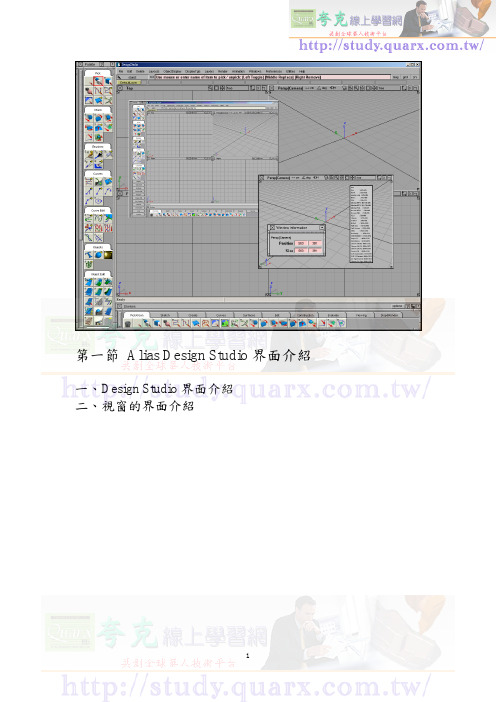
本节课将介绍使用者的环境及界面,主要是让使用者认识Alias的工作环境,以及图形化对话框式的操作界面,使用者必须充分了解这些环境界面,才能发挥Alias软件的强大功能。
一、Alias操作界面介绍1、alias的界面环境Alias具有非常亲和性的操作步骤工作环境,更有强大的曲面建模和彩像功能。
因此,与大多数CAD类的软件相比之下,更容易受到设计师的青睐。
首先来认识一下Alias的界面环境,如下图所示。
2、主题栏与其他的一般软件相同,在界面的最上方,主要是显示该软件的模组与版本,以及目前的档案名称和档案的存放路径,如下图所示。
3、下拉式功能表下拉式功能表位于主题栏的下方,主要提供使用者基本的绘图编辑指令与其他工具。
4、选取状态位于下拉功能表的下方,其功能是显示欲在绘图区选取的曲线、曲面或其他物件的形式。
使用者课与工具箱点选选取工具列中的任意指令,此时,欲选取的物件形式将会在该栏位中显示。
5、提示列下拉功能表下方有一个分色的栏位,此栏位叫做Prompt Line,也就是提示列的意思,如下图所示。
在绘图的过程中,此处显示输入、警告、或下个步骤的操作信息,按下左边的按钮,将显示之前所出现的提示,如下图所示。
6、锁定键位于提示列右侧,此三个按钮的功能是用来吸附控制点、编辑点、格线与曲线。
第一个代表吸附的位置将会在最近的控制点或编辑点上。
第二个代表吸附的位置将会在最近的格线交点上。
第三个代表吸附的位置将会在曲线上。
7、图层列图层列是让使用者组织与归类各种不同种类的物件,包括点、曲线、曲面等物件。
透过图层的管理,所有的物件才不会混乱不清,另外图层的颜色可帮助使用者更好的辨别各种不同的物件元素,让不同属性的物件有专属的图层。
8、绘图区顾名思义就是绘图的视窗区域,可执行下拉功能表的Layouts>>All windows>> All windows (所有视窗),系统将显示四个视窗,分别为顶视图、前视图、透视图、右视图。
alias入门教程

想学到更多欢迎加入群385297399
1. 目前最先进的工业设计造型软件 2. 汽车行业最常用的解决方案 3. 最高效的工作界面 4. 设计师思想最有效的表达工具之一
想学到更多欢迎加入群385297399
1.Palette详解
想学到更多欢迎加入群385297399
想学到更多欢迎加入群385297399
8,将上述操作完的空隙用自由桥接连接起来,注意一段G2,一段G0,并 且末端方式为default,并且把连接好的这块面对称过去,效果如右图:
ห้องสมุดไป่ตู้
想学到更多欢迎加入群385297399
好多人都说alias学起来很难,而不敢靠近它,我的观点是alias要想用好确实 不易,但是它终究是一个工具,对人类来说掌握一门新工具不是特别难,多 学多练即可,况且alias高效友好的界面实在诱人,所以想学还没动手的孩纸 别犹豫了!!还有人说alias没有官方版的中文,其实这不是重点,软件里边 就那么些单词而且好多都是初级词汇,真正碰到alias关于英文的问题是国内 alias相关资料少之又少,好多你得去国外网站搜索资料,当然,当你真正因 为一个alias问题不得已去国外网站找资料的时候,那么,骚年alias你已经很 牛X了!!! 那这个简单教程就讲到这里,后期我估计还会给大家对于一些细节问题以 PPT或PDF格式写点教程,希望大家喜欢。 祝大家中秋节快乐! 谢谢。 教程里边所有图片打包下载:/s/1csjCU
想学到更多欢迎加入群385297399
2,这条曲线我们是在front视图中绘制的,接下来我们进入top视图继续 对曲线进行调节。使它变成如图所示形状。并且对称复制一条。如右图;
想学到更多欢迎加入群385297399
linux中alias的用法

linux中alias的用法在Linux操作系统中,别名(alias)是一种便捷的工具,可以帮助用户更轻松地访问和管理文件和命令。
别名是一个已存在的文件或命令的别称,它可以简化命令行输入,提高工作效率。
下面我们将详细介绍Linux中别名的用法、创建方法以及注意事项。
一、Linux中alias的概述在Linux系统中,别名本质上是一个文本字符串,它指向一个文件或命令。
别名可以简化复杂的命令,使得用户可以更容易地访问常用的功能。
别名不仅可以用于文件,还可以用于目录和命令。
通过使用别名,用户可以自定义自己的命令行环境,使其更加符合个人需求。
二、创建和使用别名的方法1.创建别名:在Linux系统中,可以使用`alias`命令创建别名。
例如,如果你想要为`ls`命令创建一个别名`l`,可以使用以下命令:```alias l="ls"```2.使用别名:创建别名后,可以在命令行中直接使用新的别名。
例如,使用上面创建的别名`l`,可以这样输入:```l```这将执行与`ls`命令相同的功能。
3.删除别名:如果不再需要某个别名,可以使用`unalias`命令删除。
例如,要删除上面创建的别名`l`,可以使用以下命令:```unalias l```三、别名的优势和注意事项1.别名的优势:- 简化命令行输入,提高输入速度;- 自定义命令行环境,使操作更加便捷;- 帮助新手更快地熟悉常用命令。
2.注意事项:- 别名不影响原命令的执行,只是改变了命令的调用方式;- 别名对于不同用户是独立的,一个用户创建的别名另一个用户无法直接使用;- 别名不影响系统默认的命令,如果需要更改默认命令,需要修改配置文件。
四、举例说明别名的应用场景1.简化常用命令:对于一些频繁使用的命令,如`ls`、`cd`等,可以创建别名,提高输入速度。
2.方便快捷地切换目录:可以使用别名创建一个指向常用目录的别名,例如`~/work`,从而方便地在不同目录间切换。
Alias教学-基础篇 基本选项

Alias教学-基础篇基本选项01Pick:Pick object(选取物体)鼠标左/右选择/取消Pick component(选取组件)鼠标左/右选择/取消Pick template (选取模板)鼠标左/右选择/取消Pick edit point(选取编辑点)鼠标左/右选择/取消Pick CV (选取角度) 鼠标左/右选择/取消Pick curve-on-surface (选取曲面上的线) 鼠标左/右选择/取消Pick locator (选取定位) 鼠标左/右选择/取消Pick visible (选取可见的) 鼠标左/右选择/取消Transform :Move (移动) 移动模型按住Alt移动物体可捕捉网格线,按住右键拖动鼠标是把所选物体沿着z轴移动,按住中间键是沿着x轴移动。
Rotate (旋转)左键沿x轴方向中键沿Y轴方向右键沿z轴方向Scale (同比测量)改变模型的大小长短按左键Nonproportional Scale (不同比例测量)改变模型的大小长短按左键左键=自由缩放中间键=水平缩放右键=垂直缩放Proportional modification (成比例修改)Set pivot (建立支点)Drag keypoints (拖曳关键点)Zero transforms (零转换)使所有转换归零Place (移动到指定位置)Paint :Pencil (铅笔)Marker Ink (马克水笔)Airbrush soft (喷枪)Brush Felt (笔刷)Eraser soft (橡皮)Sharpen brush (锐化笔刷)FloodFill (油漆桶)Pick lay By color (根据颜色选图层)Magic Wand (魔术棒)Make image shape outline (描边)Text image (文字图层)Modify canvas brush symmetry (对称修改)Color Editor (颜色编辑)Paint Editor :Transform layer (变换图层)Deform image layer (改变图像有点像PS里的Ctrl-T)make warp shape (弯曲)Brightness & contrast (亮度对比度)Sharpen layer (锐化图层)New image layer (新建图层)Curves :Circle (圆形)New curves (CVs) (新建曲线)Blend curve toolbox (混合曲线工具库)New curve –on-surface (在面上新建曲线)Line (直线)Arc(3 point) (3个点的圆弧)Line tangent to curve (直线曲线点画圆弧)Line –arc (直线画圆弧)Text (文字)Curves Edit :Duplicate curve (复制曲线)Transform curve (曲线变形)Break curve at keypoint (在基点处分开曲线)Rebuild curve (重组曲线)Project tangent (投影切线)curve planarize (将曲线延伸成平面)section a group of curve (剪切一组曲线)Fit curve (适合的曲线)Sorts curve sections (曲线段分类)02Object Edit :2008-5-27 16:15:13 上传下载附件(1.06 KB) Attach (连接)2008-5-27 16:15:13 上传下载附件(1023 Bytes) Insert (插入)2008-5-27 16:15:13 上传下载附件(1.03 KB) Extend (延伸)2008-5-27 16:15:13 上传下载附件(1.01 KB) Align (排列)2008-5-27 16:15:13 上传下载附件(1.02 KB) Offset (平移)2008-5-27 16:15:13 上传下载附件(1.14 KB) Reverse direction (反向)2008-5-27 16:15:13 上传下载附件(1.04 KB) Lattice Rig (网格变形)2008-5-27 16:15:13 上传下载附件(1.12 KB)Object editor (对象编辑)2008-5-27 16:15:13 上传下载附件(1.1 KB)close (闭合)2008-5-27 16:15:13 上传下载附件(1 KB)Edit comment (编辑评语)2008-5-27 16:15:13 上传下载附件(1.11 KB)Patch precision (平滑面片)2008-5-27 16:15:13 上传下载附件(1.01 KB)Query edit (查询编辑器)Surfaces :2008-5-27 16:32:46 上传下载附件(1.08 KB) Sphere (球体)2008-5-27 16:32:46 上传下载附件(1.08 KB)Set planar (平面设置)2008-5-27 16:32:46 上传下载附件(1.11 KB) Revolve surface (旋转平面)2008-5-27 16:32:46 上传下载附件(1.06 KB)Skin surface (肤覆曲面)2008-5-27 16:32:46 上传下载附件(1.09 KB)Rail surface (轨面成形)2008-5-27 16:32:46 上传下载附件(1.09 KB)Square surface (四方平面)2008-5-27 16:32:46 上传下载附件(1.08 KB) Surface fillet (表面倒角)2008-5-27 16:32:46 上传下载附件(1.08 KB) Freeform blend (任意弯曲)2008-5-27 16:32:46 上传下载附件(1.07 KB)Fillet flange (边缘倒角)下载附件(1.06 KB)Round (圆角)2008-5-27 16:32:46 上传下载附件(1.11 KB)Multi-surface draft (多边形草图)2008-5-27 16:32:46 上传下载附件(1.09 KB)Curve networks (网格曲线)2008-5-27 16:32:46 上传下载附件(1.1 KB)Combine surfaces (连接曲面)Surfaces Edit :2008-6-24 16:14:29 上传下载附件(1.14 KB)Project (投影)2008-6-24 16:14:29 上传下载附件(1.09 KB)Trim (剪切)2008-6-24 16:14:29 上传下载附件(1.15 KB)Shell stitch (缝合外形)下载附件(1.08 KB)Shell subtract (布尔运算)2008-6-24 16:14:29 上传下载附件(1.1 KB)Planarize hull (实体表面平面化)2008-6-24 16:14:29 上传下载附件(1.07 KB)Rebuild surface (重建曲面)Mesh :2008-6-24 16:18:31 上传下载附件(1.06 KB)Nurbs to mesh (Nurbs网格)2008-6-24 16:18:31 上传下载附件(1.17 KB)Mesh subset (网格子集)2008-6-24 16:18:31 上传下载附件(1.13 KB)Mesh project curve (网格投影)2008-6-24 16:18:31 上传下载附件(1.05 KB)Mesh weld vertices (定点连接)下载附件(1.07 KB)Mesh repair (网格修复)2008-6-24 16:18:31 上传下载附件(1.17 KB)Mesh Reverse Normal (反方向)2008-6-24 16:18:31 上传下载附件(1.08 KB)Polyset to mesh (将polyset转换为网格)View :2008-6-24 16:28:18 上传下载附件(1.18 KB)Tumble (翻转)2008-6-24 16:28:18 上传下载附件(1.15 KB)Twist (螺旋)2008-6-24 16:28:18 上传下载附件(1.09 KB)Zoom (放大缩小)2008-6-24 16:28:18 上传下载附件(1.07 KB)Look out (查看)下载附件(1.08 KB)Previous (返回上一级菜单)2008-6-24 16:28:18 上传下载附件(1018 Bytes)Reset view (重新安排视图)2008-6-24 16:28:18 上传下载附件(1.05 KB)New camera (新建相机)2008-6-24 16:28:18 上传下载附件(1.04 KB)Adjust clipping plane (调整被剪平面)2008-6-24 16:28:18 上传下载附件(1.09 KB)1:1calibrate (1:1校对)Construction :2008-6-24 16:31:52 上传下载附件(1.11 KB)Point (点)2008-6-24 16:31:52 上传下载附件(1016 Bytes)Vector (向量)下载附件(1.08 KB)Plane (平面)2008-6-24 16:31:52 上传下载附件(1.01 KB)Set construction plane (建立组合平面)2008-6-24 16:31:52 上传下载附件(1.05 KB)Toggle construction plane (连接平面)2008-6-24 16:31:52 上传下载附件(1.04 KB)Grid preset (删格形式)Locators :2008-6-24 16:36:27 上传下载附件(1.08 KB)Move locator (移动位置)2008-6-24 16:36:27 上传下载附件(990 Bytes)Annotate (注释)2008-6-24 16:36:27 上传下载附件(1.11 KB)Measure distance (测量距离)下载附件(1.11 KB)Closest point deviation (最近点偏差)2008-6-24 16:36:27 上传下载附件(1.09 KB)Curve curvature (曲线曲率)Evaluate :2008-6-24 16:45:17 上传下载附件(1.12 KB)Surface continuity (连续表面)2008-6-24 16:45:17 上传下载附件(1.14 KB)Horizon (地平线)2008-6-24 16:45:17 上传下载附件(1.12 KB)Cross section (横截面)2008-6-24 16:45:17 上传下载附件(1.17 KB)Parting line (分缝线)2008-6-24 16:45:17 上传下载附件(1.17 KB)Min/Max curvature (最大最小曲率)Mass properties (人工扫描)2008-6-24 16:45:17 上传下载附件(1.18 KB)Check model (检查模型)2008-6-24 16:45:17 上传下载附件(1.07 KB) Deviation map (反差图)。
ALIAS手册
Alias V8.0繪圖基礎課程手冊閆嬰紅著Alias/Wavefront目錄第一章ALIAS入門 (1)第二章MODEL的基本知識 (5)第三章基本幾何形狀建構 (7)第四章繪製茶壺 (8)第五章繪製音箱 (11)第六章RENDER模組基本介紹 (16)第七章繪製眼鏡 (18)第八章蠟燭檯 (23)第九章ANIMATION模組基本介紹 (31)第十章使用桌燈的動畫說明 (34)第一章Alias入門第一節學習內容歡迎使用Alias 8.0版,在這本書中您將在3D工作環境中學習如何構建模型、設定材質、動畫模擬等技巧。
首先,本章將帶領您認識Alias 的模組以及使用者介面(User Interface)。
第二節模組定義Alias是由加拿大Alias/Wavefront公司所設計、開發出來的軟體,主要應用在工業設計以及動畫的領域,本套軟體不論任何等級,都具有以下三個模組:1. 模型模組:主要是建構、編輯以及分析的工具,可以產生2D以及3D的模型,以面架構(Surface Model)作為軟體構建基礎。
2. 彩像模組:設定模型的色彩、材質、燈光、背景等,透過Quick Render、Raycast、Raytracing算圖程式,可以將設計的物體如相片般呈現出來。
3. 動畫模組:將3D模型以動態的方式呈現,目的在讓觀賞者能更瞭解設計者的意圖。
第三節使用者介面說明Alias使用者介面設計是採用圖示與文字並列的方式編排,,User可以依照自己習慣的方式使用,這些工具包含選單(Menu)、熱鍵(Hot Key)、調色盤(Palette)以及新的工具架(Shelf)。
1. 執行Alias軟體在簽入電腦系統之後,在螢幕中會看到Alias 的icon,若要執行Alias,請在icon上雙響(Double-Click)。
2. 等待數秒後,在螢幕上會出現Alias工作環境,再按下<Alt + w>,會出現如下繪圖環境。
- 1、下载文档前请自行甄别文档内容的完整性,平台不提供额外的编辑、内容补充、找答案等附加服务。
- 2、"仅部分预览"的文档,不可在线预览部分如存在完整性等问题,可反馈申请退款(可完整预览的文档不适用该条件!)。
- 3、如文档侵犯您的权益,请联系客服反馈,我们会尽快为您处理(人工客服工作时间:9:00-18:30)。
Alias初级教程一操作环境介绍
特别鸣谢:老A
整理:中国汽车工程群(7234594)
本节课将介绍使用者的环境及界面,主要是让使用者认识Alias的工作环境,以及图形化对话框式的操作界面,使用者必须充分了解这些环境界面,才能发挥Alias软件的强大功能。
一、Alias操作界面介绍
1、alias的界面环境
Alias具有非常亲和性的操作步骤工作环境,更有强大的曲面建模和彩像功能。
因此,与大多数CAD类的软件相比之下,更容易受到设计师的青睐。
首先来认识一下Alias的界面环境,如下图所示。
2、主题栏
与其他的一般软件相同,在界面的最上方,主要是显示该软件的模组与版本,以及目前的档案名称和档案的存放路径,如下图所示。
3、下拉式功能表
下拉式功能表位于主题栏的下方,主要提供使用者基本的绘图编辑指令与其他工具。
4、选取状态
位于下拉功能表的下方,其功能是显示欲在绘图区选取的曲线、曲面或其他物件的形式。
使用者课与工具箱点选选取工具列中的任意指令,此时,欲选取的物件形式将会在该栏位中显示。
5、提示列
下拉功能表下方有一个分色的栏位,此栏位叫做Prompt Line,也就是提示列的意思,如下图所示。
在绘图的过程中,此处显示输入、警告、或下个步骤的操作信息,按下左边的按钮,将显示之前所出现的提示,如下图所示。
6、锁定键
位于提示列右侧,此三个按钮的功能是用来吸附控制点、编辑点、格线与曲线。
第一个代表吸附的位置将会在最近的控制点或编辑点上。
第二个代表吸附的位置将会在最近的格线交点上。
第三个代表吸附的位置将会在曲线上。
7、图层列
图层列是让使用者组织与归类各种不同种类的物件,包括点、曲线、曲面等物件。
透过图层的管理,所有的物件才不会混乱不清,另外图层的颜色可帮助使用者更好的辨别各种不同的物件元素,让不同属性的物件有专属的图层。
8、绘图区
顾名思义就是绘图的视窗区域,可执行下拉功能表的Layouts>>All windows>>All windows(所有视窗),系统将显示四个视窗,分别为顶视图、前视图、透视图、右视图。
当视窗正为绘图状态时,视窗的周围将显示白色的色框,如下图的透视图所示。
9、视窗名称
每个视窗的左上角都会显示视窗名称,如图所示
10、系统坐标
系统坐标位于每个视窗的左下方,主要是让使用者清楚现在的视窗坐标位置,红色代表X轴,绿色代表Y轴,蓝色代表Z轴。
另外在使用Xform变形指令时,也要注意左下方视图的坐标轴向,因为鼠标的左中右三键,也分别代表XYZ轴向。
11、指令功能说明
指令功能说明位于绘图区的下方,可将游标随意移至任一个指令列的图示,此栏位将会显示指令的功能说明,比如我鼠标移动至新建画线工具位置,如下图会显示。
12、工具箱
所有的指令图示都存放在Palette工具箱中,并且依照其指令功能的相似性分层,以类似档案夹的标签来存放,每个标签内含有数目不等的指令图示。
点选工具箱的标签可缩放整个工具列。
如下图所示。
13、自定工具箱
Shelves称为自定工具箱,此工具箱的用途是将平时教常用的指令图示,依照自己的习惯使其分门别类,规划合适的标签,并自行增加或删除,以减少寻找或点选指令的时间,提高工作效率。
如下图
二、Alias视图窗口介绍
视窗的界面介绍
本节课说明视窗的界面,在每个视窗上有许多的功能图示,大部分都是控制视窗的状态,以下将分别说明其功能与操作方法。
1、关闭视窗
此按钮用来关闭视窗
2、视窗名称
每个视窗的左上方都会有视窗的名称
3、线性单位
系统空间坐标的线性单位,也就是网格的距离是以mm为基本单位。
使用者若需更改系统的线性单位,可执行下拉功能表的Preferences>>Construction option(建构选项),此时将显示建构选项对话框,如下图所示。
在对话框中可重新设定线性的比例值、主单位、次单位、定位单位、格线。
4、网格间距
格线与格线间的距离
下课待续.......。