WT_SOM9854_S1核心板说明书(1)
海克智动 智能主控板说明书
海克智动智能主控板说明书
1、简介
智能主控板是新风机中控制风机、风阀等主控电路板,我们目前有两种主控板,即220VAC电容调速三档、220VAC强控三档。
新风机就是客户自己的新风主机,我们帮助客户设计新风主机的主控电路板,主控板控制风机、新风阀、电击离子、通信接口(RS-485)等。
新风机可以通过B3工业空气质量监测仪的空气质量数据自动运行,也可以通过液晶触控屏手动控制新风机运行状态。
具体运行状态可根据客户实际要求设计。
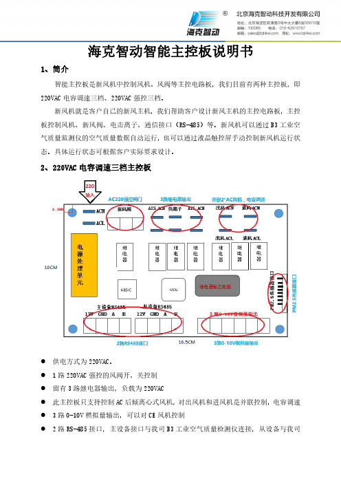
2、220VAC电容调速三档主控板
●供电方式为220VAC。
●1路220VAC强控的风阀开、关控制
●留有3路继电器输出,负载为220VAC
●此主控板只支持控制AC后倾离心式风机,对出风机和进风机是并联控制,电容调速●3路0-10V模拟量输出,可以对CE风机控制
●2路RS-485接口,主设备接口与我司B3工业空气质量检测仪连接,从设备与我司
X3液晶触控屏连接
●1路PM2.5传感器接口,可以与我司PM2.5传感器连接
3、220VAC强控三档主控板
●供电方式,交流220V
●风机控制是220VAC强控三档调速
●3路继电器输出,负载为220VACV
●2组风阀220VAC强控开、闭
●2路模拟量输入,0-10V的AD转换
●4路数字量输入,高达10V的数字量
●2路0-10V模拟量输出,可以对CE风机控制
●2路RS485接口,主设备接口与我司B3工业空气质量监测仪连接,从设备与我司X3
液晶触控屏连接。
AD9850_1模块使说明书

串并模式转 换插针 数据接口
正弦波输出 RF-OUT
矩形波输出
正弦波幅度 调节 200mV-2V 电源接反保 护 AD9850 125M AD9851 30M 70M 滤波器
矩形波输出
插入跳线帽短路为串行 模式,断开为并行模式。
模块测试============================================================
1:朋友拿到模块后,先不急着调电位器,电位器出厂已调到幅度调到 2V VPP。朋友调试 出信号后,如果有需要再调节电位器,调幅度。 2:问我按照你的方法接怎么不出信号。 答:给大家的模块和程序都是已经调试成功程序是标准 51 C 程序。如果是别的类型单片机 如 STM32,AVR,MSP430 请朋友自行移值。朋友要注意一些比如自已的单片机 IO 口是不 是连其它器件,比如 DS18B20 DS1302 数码管等一些器件。这些器件会影响时序,导致出 不来信号。 3:为什么程序给了 1K 的信号,但出来频率相差很多。 答:这里由于 D0-D7 数据口跟单片机数据口没有连好导致。请朋友仔细检查核对后,肯定 OK! 4:你的模块可以用 3.3V 供电吗? 答:模块设计在 5V 供电,在 3.3V 勉强能用,但不建议! 5:我用示波器量,出来的波形幅度怎么用 20 多 V? 答:模块采用 5V 供电,不可能出 20 多 V,唯一可能就是示波器表笔打到*1 档,再把示波 器打到*10 就恢复了。 6:为什么我的正弦波出来了,但方波出不来 答:可能是调节占空比电位器调的太多了,重新调试即可解决
J2)
RF_OUT 端能测试到对应输出 1KHz 正弦波信号幅度 2V VPP。如需测试方波,调节可 变电位器,在 VOUTP 和 VOUTN 端测试到方波。电位器调节占空比
集特核心板GCE-2001-01说明书

说明除列明随产品配置的配件外,本手册包含的内容并不代表本公司的承诺,本公司保留对此手册更改的权利,且不另行通知。
对于任何因安装、使用不当而导致的直接、间接、有意或无意的损坏及隐患概不负责。
订购产品前,请向经销商详细了解产品性能是否符合您的需求。
本手册所涉及到的其他商标,其所有权为相应的产品厂家所拥有。
本手册内容受版权保护,版权所有。
未经许可,不得以机械的、电子的或其它任何方式进行复制。
温馨提示1、产品使用前,务必请仔细阅读产品说明书。
2、对未准备安装的主板,应将其保存在防静电保护袋中。
3、在从包装袋中拿主板前,应将手先置于接地金属物体上一会儿,以释放身体及手中的静电4、在使用前,宜将主板置于稳固的平面上。
5、请保持主板的干燥,散热片的开口缝槽是用于通风,避免机箱内的部件过热。
请勿将此类开口掩盖或堵塞。
6、在将主板与电源连接前,请确认电源电压值。
7、请将电源线置于不会被践踏的地方,且不要在电源线上堆置任何物件。
8、当您需连接或拔除任何设备前,须确定所有的电源线事先已被拔掉。
9、为避免人体被电击或产品被损坏,在每次对整机、板卡进行拔插或重新配置时,须先关闭交流电源或将交流电源线从电源插座中拔掉。
10、请留意手册上提到的所有注意和警告事项。
11、为避免频繁开关机对产品造成不必要的损伤,关机后,应至少等待30秒后再开机。
12、设备在使用过程中出现异常情况,请找专业人员处理。
13、请不要将本设备置于或保存在环境温度高于70℃上,否则会对设备造成伤害。
目录目录 (1)1.产品简介 (1)1.1概述11.2产品特点 (2)1.3产品指标 (2)2.细参数说明 (4)2.1COMe外形尺寸 (4)2.2COMe连接器接口定义 (5)1.产品简介1.1概述GCE-2001-01基于飞腾D2000-8处理器的COMe模块,模块按照PICMG COMExpress 规范设计,符合COMExpress Type6Rev2.0接口类型定义,尺寸规格为Basic规格。
Omega CSC32K Benchtop Controller产品说明书

P
CSC32K Benchtop Controller shown with LHM Series Heating Mantle, $139, (Flask not included), and KMTXL-125G-12 Thermocouple Probe, $27.95. See page A-45.
0.5 (0.9) 0.25 (4.5)
0 to 50 mV (1 Ω shunt resistor
Copper-Constantan
-200 to -250°C/-273 to 482°F
0.25 (4.5)
supplied for mA inputs) Calibration Accuracy: ±0.25% of Full Scale ±1.5°C (±2.7°F)
• In addition, up to 12 controllers can be displayed on a single chart, or individual charts can be set up for each instrument.
• A virtual full color chart recorder can log process variables such as: °C, °F, Bar, PSI, pH, rH, or user defined engineering units
RTD, Process Voltage or Current Input
ߜ Two 5 Amp 120 Vac SSR Outputs Standard
ߜ Second Output May be Used for Control or One of Five Types of Alarms
智能TFT-LCD模块STWI104WT-01设备说明书

Intelligent TFT-LCD ModuleModelSTWI104WT-01Equipment ManualContentsPreface (3)1 Introduction (5)2 Technical Parameters (10)3 Interface Description (15)4 Accessories (16)5 Physical Dimensions (18)6 Electrical Components (19)7 Naming Rule (20)8 International Certification (21)APPENDIX (22)Glossary (24)PrefaceThis equipment manual is part of our Intelligent TFT-LCD Module documentation. It provides the information in regards of operation, installation, configuration, function, system as well as its technical design and working principle.Organization of the manualThe STWI104WT-01 equipment manual is organized into the following chapters:Products through its Online services as follows:- Official website: https:///https://- Official forum: https:///- Telephone: 0086-10-84351669Other supportIn need of technical queries, please contact STONE representatives in the subsidiaries and branches responsible for your area.PrefaceTrademarksSTONE registered trademarks are as below:- STONE- STONE TECH- Intelligent HMI- Intelligent TFT-LCD Module- Smart TFT-LCD ModuleAbbreviationsThe abbreviation table in this equipment manual is as below:LED Light Emitting DiodeCPU Central Processing UnitESD Electrostatic Sensitive DeviceHMI Human Machine InterfaceIF InterfaceLCD Liquid Crystal DisplayUART Universal Asynchronous Receiver/TransmitterCOM CommercialDIN Data InputDOUT Data OutputVIN Voltage InputGND GroundTP Touch PanelA list of all the technical terms together with their explanations is provided in the glossary at the end of this manual.1IntroductionThis chapter contains general information of:- Brief Introduction- Warranty- Product Characteristics- Application Area- Working principle- Operation Processing- Software OperationIntroduction1.1 Brief IntroductionThe STWI104WT-01 has been used as Equipment TFT dispaly & Touch controller. It includes processor, control program, TFT driver, flash memory, UART port, touch screen, power supply etc., and the important is it can supply the Json Code & Hex Code instruction sets, so that it can be controlled by Any MCU.The STWI104WT-01 can perform all basic functions, such as Vector font display, image display, curve display as well as touch function, Video & Audio function etc. The User Interface can be more abundant and various. And the flash memory can store your data, configuration files, image file, font file, video file and audio file etc.1.2 WarrantyAll products purchased from our company are guaranteed to keep in good repair for3 years. If quality problems (except human error) happen in guarantee period, our company will maintain for free to replace the broken one unconditionally.1.3 Product Characteristics- With Cortex A8 CPU / 256MB Flash / TFT Driving device- Controlled by any MCU via Json & Hex Code Instruction- Display Image / Text / Curve / Video- 262K (18bit) colour TFT display- With / without Touch Screen- RS232 / RS422 / RS485 / TTL UART Interface & USB port Downloading- Ethernet port / WIFI Remote Control- Wide voltage range / Strong Working Temperature- Easy to use! Powerful function! Saving Much Development cost and time!1.4 Application AreaWidely used in various industrial field- Medical & Beauty Equipment- Engineering Machinery and Vehicle Equipment- Electronic Instrument- Industrial Control System- Electric Power Industry- Civil Electronic Equipment- Automation Equipment- Traffic Field- New energy project- IOT applicationsEtc.Introduction1.5 Working PrincipleThe Intelligent TFT-LCD Module communicates with the Customer’sMCU / CPU / FPGA / PLC via JSON Code and HEX Code Instructions, then the MCU can control its connected equipment to work according to the received instructions.Figure 1.3-1 Configuration and process control phaseIntroduction1.6 Operation ProcessingOnly 3 steps to operate our TFT-LCD Module:⚫Build a new project by STONE GUI Design Software.⚫Connect with customer’s MCU through RS232,RS422,RS485,TTL directly, Plug & Play. ⚫Write a simple program for MCU to control the TFT-LCD Module via Instruction Sets.The communication protocol is built with 2 parts:1)Initiative Instruction - JSON Code (MCU→TFT-LCD Module)Frame header instruction code widget type widget name data Frame tail ST< {"cmd_code":"set_value","type":"label","widget":"label2","value":5} >ET 2)Passive Instruction - HEX Code (TFT-LCD Module→MCU)Frame header CMD LEN DATA Frame tail CRC16 53 54 3C 10 62 00 096C 61 62 65 6C 3F A1 47 AE3E 45 54 6C 8B More information, please refer to the document of Instruction Sets.Introduction.7 Software OperationWe will offer a simple & powerful "Stone GUI design Software" to help you to design the new project for Intelligent TFT-LCD Module basic on Windows system or MacOS system.2Technical ParametersThis chapter contains technical data on:- Physical Parameters:Physical ParametersDisplay- Hardware Parameters:ProcessorMemoryInterfacePower Supply- Storage & TestElectrical CharacteristicsAmbient ConditionsNoise ImmunityRadio Interference- Support DeviceSupport DeviceTechnical ParametersTechnical ParametersTechnical ParametersTechnical Parameters3Interface DescriptionThis chapter contains the description of the interfaces:- VVC- NC- DOUT- DIN- GNDCommunication Interface DefinitionI: Input O: Output P: Power: 1. Adopting the 8 Pin 2mm spacing socket. Model Code: A2008WR-S-8P2. Direction of the signal was defined with TFT-LCD Module;“I” refers to the signal from the user’s MCU transmitted to the TFT-LCD Module.3. Pins with the same definition are connected together in the module inside.4. RS232, RS422, RS485, TTL port can be default which need to point out in the order.: The selection of Baud rate for the serial interfaceBaud rate120024004800)Serial Port Defind:4AccessoriesThis chapter contains the accessories:- Double 8-pin Connect Cable- 8-pin Socket- Type A USB Cable- Converter: USB ⇌ RS232 / RS422 / RS485 / TTL - IP65 Plastic Box (optional)- Metal Bezel (optional)This chapter contains the information of Physical Dimensions.Figure 5-1 STWI104WT-01 dimensionThis chapter contains the brands of the components:- TFT Panel- Touch Screen- CPU- LCD Controller- Flash memory- Connecter- Capacitance- IC7Naming RuleThis chapter contains the naming rule: As sample STWI070WT-01E8International CertificationThis chapter contains the certification we passed:- CE Certificate- ROHS Certificate- FCC Certificate- ISO9001:2008 Quality SystemCE Certificate FCC CertificateRoHS Certificate ISO9001:2008APPENDIXAPPENDIXESD GuidelinesWhat does ESD mean?Virtually all present-day modules incorporate highly integrated MOS devices or components. For technological reasons, these electronic components are very sensitive to overvoltages and consequently therefore to electrostatic discharge:These devices are referred to in German as Elektrostatisch GefährdetenBauelemente/ Baugruppen: ºEGBºThe more frequent international name is:ºESDº (E lectrostatic Sensitive Device)The following symbol on plates on cabinets, mounting racks or packages draws attention to the use of electrostatic sensitive devices and thus to the contact sensitivity of the assemblies concerned:ESDs may be destroyed by voltages and energies well below the perception threshold of persons. Voltages of this kind occur as soon as a device or an assembly is touched by a person who is not electrostatically discharged . Devices exposed to such overvoltages cannot immediately be detected as defective in the majority of cases since faulty behavior may occur only after a long period of operation.Precautions against electrostatic dischargeMost plastics are capable of carrying high charges and it is therefore imperative that they be kept away from sensitive components.When handling electrostatic sensitive devices, make sure that persons, workplaces andpackages are properly grounded.APPENDIX Handling ESD assembliesA general rule is that assemblies should be touched only when this cannot be avoided owing to the work that has to performed on them. Under no circumstances should you handle printed-circuit boards by touching device pins or circuitry.You should touch devices only if● you are grounded by permanently wearing an ESD wrist strap or●you are wearing ESD shoes or ESD shoe-grounding protection straps in conjunctionwith an ESD floor.Before you touch an electronic assembly, your body must be discharged. The simplest way of doing this is to touch a conductive, grounded object immediately beforehand ± for example, bare metal parts of a cabinet, water pipe etc.Assemblies should not be brought into contact with charge-susceptible and highly insulating materials such as plastic films, insulating table tops and items of clothing etc. containing synthetic fibers.Assemblies should be deposited only on conductive surfaces (tables with an ESD coating, conductive ESD cellular material, ESD bags, ESD shipping containers).Do not place assemblies near visual display units, monitors or television sets (minimum distance to screen > 10 cm).Measuring and modifying ESD assembliesPerform measurements on ESD assemblies only when● the measuring instrument is grounded ± for example, by means of a protective conductor± or● the measuring head has been briefly discharged before measurements are made with a potential-free measuring instrument ± for example, by touching a bare metal control cabinet.When soldering, use only grounded soldering irons.Shipping ESD assembliesAlways store and ship assemblies and devices in conductive packing ± for example, metallized plastic boxes and tin cans.If packing is not conductive, assemblies must be conductively wrapped before they are packed. You can use, for example, conductive foam rubber, ESD bags, domestic aluminum foil or paper (never use plastic bags or foils).With assemblies containing fitted batteries, make sure that the conductive packing does not come into contact with or short-circuit battery connectors. If necessary, cover the connectors beforehand with insulating tape or insulating material.GlossaryBaud rateRate of speed at which data is downloaded. Baud rate is specified in Bit/s.BootA loading process which downloads the operating system in the working memory of the operating unit.Command SetHex Code, the MCU can control the TFT Module via the command set.Configuration fileIt can be created by the softwares.DownloadDownload the image, configuration files and data through mini USB port or USB port.Download modeThrough mini USB port or USB port.GlossaryFlash memoryProgrammable memory which can be electrically deleted and written to again segment-by-segment.Half Brightness LifeThe period of time after which the brightness tube only achieves 50% of the original value.Input fieldEnables the user to enter values which are subsequently sent to the MCU.MCUMicro Control Unit, it is widely used in the industrial control.Normal operationOperating unit operating mode in which messages are displayed and screens can be operated.GlossaryOutput fieldDisplays current values from the MCU on the operating unit.Process screenThe display of process values and process progress on the operating unit in the form of screens, which may contain graphics, texts and values.RS485Standard interface for serial data transfer at a very high transmission rate.ScreenA screen displays all the logically related process data on the operating unit, wherebythe individual values can be modified.Touch panelThis is an operating unit without a keyboard. The touch panel (abbreviated to TP) is operated via the contact-sensitive screen elements.。
高科特实际产品说明书
4
Specifications are subject to change without notice (21.06.2021)
Solid State Relays Accessories, Screw Kits Types SRWKIT…
Ordering Key
Screw Kit Screw size Screw length
0.5 Nm -20° to + 70°C [-4 to +158°F] -40° to + 100°C [-40° to +212°F] DIN EN 50022, 50035
DIN Adaptor for 1-phase SSRs
DIN rail adaptor module for mounting the 1-phase SSR series RA, RD, RM, RS and RAM directly on DIN rail.
Type
UL style 2547 UL style 2464 UL style 2464 UL style 2464 UL style 2464 UL style 2464
Cable size
0.14mm2 0.14mm2 0.14mm2 0.25mm2 0.14mm2 0.14mm2
Termination
- Width x Height x Thickness = 35 x 43 x 0.25 mm
- Packing qty. 50 pcs.
RZHT
- Graphite thermal pad for RZ3 series with adhesive on one side
- Width x Height x Thickness = 70 x 77 x 0.25 mm
华克仕 K-FT2K-Core 核心板说明书

使用产品之前请仔细阅读产品说明书K-FT2K-Core核心板说明书版本:v1.1版本更新表目录1注意事项 (1)2产品概述 (2)3产品规格 (3)4实物接口介绍 (4)4.1主板正反面图 (4)4.2主板加散热器图 (5)4.3主板尺寸图 (6)5接口功能定义 (7)5.1功能分布图 (7)5.2丝印描述 (8)5.3接口定义 (9)1注意事项商标本手册所提及的商标与名称都归其所属公司所有。
注意1. 使用前,请先详细阅读说明书,避免误操作导致产品损坏;2. 请将此产品放置在-20℃<=工作环境<=+60℃、90%RH的环境下,以免因过冷、热或受潮导致产品损坏;3 请勿将此产品做强烈的机械运动,以及在没有作好静电防护之前对此产品操作;4. 在安装任何外接卡或模组之前,請先关闭电源;5. 禁止对主板产品进行私自更改、拆焊,对此所导致的任何后果我司不承担任何责任;K-FT2K-Core是一款基于飞腾FT-2000/4处理器,采用采用COM Express Basic板型的核心板,尺寸为125*95mm。
K-FT2K-Core采用飞腾FT-2000/4四核芯处理器。
板载2条DDR4 SO-DIMM内存插槽。
K-FT2k-Core的COMe插槽,集成2路MAC,可外加PHY芯片扩展出2路千兆网口;集成1*PCIe-X16、2*PCIe-X8、2*PCIe-X1扩展资源,集成4*UART接口,可扩展RS232串口;集成I2C、LPC、HDA等总线资源。
主板特点:★飞腾FT-2000/4四核芯处理器;★COM Express Basic核心板小尺寸;★板载DDR4笔记本内存插槽;★丰富的PCIe扩展资源;4实物接口介绍4.1主板正反面图4.2主板加散热器图4.3主板尺寸图注意:上图单位统为毫米(mm)5接口功能定义5.1功能分布图5.2丝印描述5.3接口定义主板插针、跳线定义续1。
核星说明书
这会引起变频器内部半导体元件的损坏
-3-
1、验收
当心
l 不要安装或运行任何已经损坏或带有故障零件的变频器。 否则会导致人身伤害或设备损坏。
本章叙述变频器交付用户后的检验方法。
1-1、检验
1-1-1、验收检查 下表为检查项目: 检查项目
变频器型号是否和订单上一致? 有无部件损坏?
3、接线………………………………………………………………………………7
3-1、外围设备和任选件的接线…………………………………………………9 3-2、连接图………………………………………………………………………10 3-3、主回路的接线………………………………………………………………11 3-4、接地…………………………………………………………………………14 3-5、控制电路的接线……………………………………………………………15 3-6、接线检查……………………………………………………………………17
★ 放射性材料会影响本设备的使用。
★ 易燃物品、稀释剂、溶剂应远离本设备。
2-4、安装间隙
HX0886 系 列 变 频 器 垂 直 安 装 时 , 要 留 有 足 够 的 散 热 空 间 , 以 保 证 有 效 地 冷
却
.
-6-
出风口
出风口
大于 mm
FWD REV JOG LCL RUN FLT
MO N NEG Hz S % A
-2-
安全运行的注意事项
HX0886 系列变频器 安装、运行、维护或检查之前要认真阅读本说明书。
说明书中有关安全运行的注意事项分类成“警告”或“当心”。
警告 指出潜在的危险情况,如果不避免,可能会导致人身伤亡。
Eaton 198942 商品说明书

Eaton 198942Eaton Moeller® series Rapid Link - Speed controllers, 2.4 A, 0.75 kW, Sensor input 4, Actuator output 2, 230/277 V AC, PROFINET, HAN Q4/2, STO (Safe Torque Off)Allgemeine spezifikationEaton Moeller® series Rapid Link Speed controller198942157 mm270 mm 220 mm 3.45 kgRoHS UL approval IEC/EN 61800-5-1 CE UL 61800-5-14015081970001RASP5-2422PNT-4120010S1Product NameCatalog NumberProduct Length/Depth Product Height Product Width Product Weight Certifications Catalog Notes EANModel Code3 fixed speeds and 1 potentiometer speedcan be switched over from U/f to (vector) speed control Connection of supply voltage via adapter cable on round or flexible busbar junctionParameterization: drivesConnectParameterization: FieldbusParameterization: drivesConnect mobile (App) Parameterization: KeypadInternal DC linkKey switch position AUTOKey switch position OFF/RESETSelector switch (Positions: REV - OFF - FWD)IGBT inverterPC connectionTwo sensor inputs through M12 sockets (max. 150 mA) for quick stop and interlocked manual operationPTC thermistor monitoringThermo-click with safe isolation2 Actuator outputsControl unitKey switch position HAND3 fixed speedsSTO (Safe Torque Off)1 potentiometer speedFor actuation of motors with mechanical brake NEMA 12IP651st and 2nd environments (according to EN 61800-3)IIISpeed controllerPROFINET IOC1: for conducted emissions onlyC2, C3: depending on the motor cable length, the connected load, and ambient conditions. External radio interference suppression filters (optional) may be necessary.2000 VPhase-earthed AC supply systems are not permitted.AC voltageCenter-point earthed star network (TN-S network)Vertical15 g, Mechanical, According to IEC/EN 60068-2-27, 11 ms, Half-sinusoidal shock 11 ms, 1000 shocks per shaftResistance: 10 - 150 Hz, Oscillation frequencyResistance: 6 Hz, Amplitude 0.15 mmResistance: According to IEC/EN 60068-2-6Resistance: 57 Hz, Amplitude transition frequency on acceleration Above 1000 m with 1 % performance reduction per 100 m Max. 2000 m-10 °C40 °C-40 °C70 °CFeatures Fitted with:Functions Degree of protectionElectromagnetic compatibility Overvoltage categoryProduct categoryProtocolRadio interference classRated impulse withstand voltage (Uimp) System configuration typeMounting position Shock resistance Vibration AltitudeAmbient operating temperature - min Ambient operating temperature - max Ambient storage temperature - min Ambient storage temperature - max Climatic proofing< 95 %, no condensationIn accordance with IEC/EN 50178Current limitationAdjustable, motor, main circuit0.2 - 2.4 A, motor, main circuitDelay time< 10 ms, On-delay< 10 ms, Off-delayEfficiency97 % (η)Input current ILN at 150% overload2.5 ALeakage current at ground IPE - max3.5 mAMains current distortion120 %Mains switch-on frequencyMaximum of one time every 60 secondsMains voltage - min380 VMains voltage - max480 VMains voltage tolerance380 - 480 V (-10 %/+10 %, at 50/60 Hz)Operating modeBLDC motorsSensorless vector control (SLV)Synchronous reluctance motorsU/f controlPM and LSPM motorsOutput frequency - min0 HzOutput frequency - max500 HzOverload currentAt 40 °CFor 60 s every 600 sOverload current IL at 150% overload3.6 A45 Hz66 Hz0.75 kW400 V AC, 3-phase480 V AC, 3-phase0.1 Hz (Frequency resolution, setpoint value)200 %, IH, max. starting current (High Overload), For 2 seconds every 20 seconds, Power section50/60 Hz8 kHz, 4 - 32 kHz adjustable, fPWM, Power section, Main circuitPhase-earthed AC supply systems are not permitted.AC voltageCenter-point earthed star network (TN-S network)1 HP≤ 0.6 A (max. 6 A for 120 ms), Actuator for external motor brake≤ 30 % (I/Ie)Adjustable to 100 % (I/Ie), DC - Main circuit230/277 V AC -15 % / +10 %, Actuator for external motor brake10 kAType 1 coordination via the power bus' feeder unit, Main circuit24 V DC (-15 %/+20 %, external via AS-Interface® plug)230/277 V AC (external brake 50/60 Hz)PROFINET, optionalPlug type: HAN Q4/2Max. total power consumption from AS-Interface® power supply unit (30 V): 250 mANumber of slave addresses: 31 (AS-Interface®) Specification: S-7.4 (AS-Interface®)C2 ≤ 5 m, maximum motor cable length C1 ≤ 1 m, maximum motor cable length C3 ≤ 25 m, maximum motor cable lengthMeets the product standard's requirements.Rated frequency - minRated frequency - maxRated operational power at 380/400 V, 50 Hz, 3-phase Rated operational voltageResolutionStarting current - maxSupply frequencySwitching frequencySystem configuration type Assigned motor power at 460/480 V, 60 Hz, 3-phase Braking currentBraking torqueBraking voltageRated conditional short-circuit current (Iq)Short-circuit protection (external output circuits) Rated control voltage (Uc)Communication interfaceConnectionInterfacesCable length10.2.2 Corrosion resistanceMeets the product standard's requirements.Meets the product standard's requirements.Meets the product standard's requirements.Meets the product standard's requirements.Does not apply, since the entire switchgear needs to be evaluated.Does not apply, since the entire switchgear needs to be evaluated.Meets the product standard's requirements.Does not apply, since the entire switchgear needs to be evaluated.Meets the product standard's requirements.Does not apply, since the entire switchgear needs to be evaluated.Does not apply, since the entire switchgear needs to be evaluated.Is the panel builder's responsibility.Is the panel builder's responsibility.Is the panel builder's responsibility.Is the panel builder's responsibility.Is the panel builder's responsibility.Generation change from RA-SP to RASP 4.0 Elektromagnetische Verträglichkeit (EMV)Generation change RAMO4 to RAMO5Generation change from RA-MO to RAMO 4.0 Generationswechsel RASP4 zu RASP5Configuration to Rockwell PLC for Rapid LinkConfiguration to Rockwell PLC Rapid Link 5 Generationenwechsel RA-SP zu RASP5Generationentausch RAMO4 zu RAMO5Generation Change RA-SP to RASP5Firmware Update RASP 4.0Generationentausch RA-SP zu RASP4.0Generation Change RASP4 to RASP5Generationentausch RA-MO zu RAMO4.0Anschluss von Frequenzumrichtern an GeneratornetzeMN040003_DEMN034004_DERapid Link 5 - brochureDA-SW-drivesConnectDA-SW-drivesConnect - InstallationshilfeDA-SW-USB Driver DX-COM-STICK3-KITDA-SW-USB Driver PC Cable DX-CBL-PC-1M5DA-SW-Driver DX-CBL-PC-3M0DA-SW-drivesConnect - installation helpMaterial handling applications - airports, warehouses and intra-logistics ETN.RASP5-2422PNT-4120010S1.edzIL034093ZUDE | Rapid Link 5Sortimentskatalog Antriebstechnik-DE10.2.3.1 Verification of thermal stability of enclosures10.2.3.2 Verification of resistance of insulating materials to normal heat10.2.3.3 Resist. of insul. mat. to abnormal heat/fire by internal elect. effects10.2.4 Resistance to ultra-violet (UV) radiation10.2.5 Lifting10.2.6 Mechanical impact10.2.7 Inscriptions10.3 Degree of protection of assemblies10.4 Clearances and creepage distances10.5 Protection against electric shock10.6 Incorporation of switching devices and components10.7 Internal electrical circuits and connections10.8 Connections for external conductors10.9.2 Power-frequency electric strength10.9.3 Impulse withstand voltage10.9.4 Testing of enclosures made of insulating material Anmerkungen zur AnwendungBenutzerhandbücherBroschüreneCAD model Installationsanleitung InstallationsvideosKatalogeEaton Konzern plc Eaton-Haus30 Pembroke-Straße Dublin 4, Irland © 2023 Eaton. Alle Rechte vorbehalten. Eaton ist eine eingetrageneMarke.Alle anderen Warenzeichen sindEigentum ihrer jeweiligenBesitzer./socialmediaThe panel builder is responsible for the temperature rise calculation. Eaton will provide heat dissipation data for the devices.Is the panel builder's responsibility. The specifications for the switchgear must be observed.Is the panel builder's responsibility. The specifications for the switchgear must be observed.The device meets the requirements, provided the information in the instruction leaflet (IL) is observed.ramo5_v39.dwgrasp5_v39.stpeaton-bus-adapter-rapidlink-speed-controller-dimensions-003.eps eaton-bus-adapter-rapidlink-speed-controller-dimensions-002.eps eaton-bus-adapter-rapidlink-speed-controller-dimensions.eps eaton-bus-adapter-rapidlink-speed-controller-dimensions-004.eps10.10 Temperature rise10.11 Short-circuit rating10.12 Electromagnetic compatibility 10.13 Mechanical function mCAD model Zeichnungen。
瑞丰WI-E-045 A1 产品说明书.pdf_1718725410.5614424

applications which has special requirement in quality and reliability. 如产品需要用在有特殊质量要求及可靠性要求的地方,请提前咨询瑞丰的销售人员以取得相关信息。
4. Without Refond permission, customer shouldn’t disassemble and analyze the LEDs. If the customer find invalid product, please notice Refond in written form.在取得瑞丰的同意前,客户不应该对产品进行拆解分析,如发现失效产品,请直接书面通知瑞丰。
Features 特征Extremely wide viewing angle.发光角度大Suitable for all SMT assembly and solder process.适用于所有的SMT 组装和焊接工艺 Moisture sensitivity level: Level 3.防潮等级 Level 3Package:4000pcs/reel.包装每卷4000pcsRoHS compliant. 满足RoHS 要求Description 描述The White LED which was fabricated by using a blue chip and the phosphor 该产品为白光LED ,是由蓝光芯片激发荧光粉而形成Applications 应用Optical indicator.光学指示Switch and Symbol,Display.开关和标识、显示器等General use.其他应用Package Dimension 外观尺寸NOTES:1.All dimensions units are millimeters. (所有尺寸标注单位为毫米)2.All dimensions tolerances are ±0.2mm unless otherwise noted. (除特别标注外,所有尺寸公差为±0.2毫米)Electrical / Optical Characteristics at Ts=25°C 电性与光学特性-- -- 450Note:备注Vr=5V For test conditions. Vr=5v为测试分选条件。
Ergotron 3 8英寸1 4-20线性1.5英寸橱柜墙壁杆装置说明书
888-60-502-M-00 rev. C • 08/19 Steel Stud Mounting Kit| USA: 1-800-888-8458 | Europe: +31 (0)33-45 45 600 | China: 400-120-3051 | Användarhandbok Guida per l’utente Benutzerhandbuch 用户指南ユーザーガイドGebruikersgids Manuel de l’utilisateur Guía del usuarioUser Guide888-60-502-M-00 rev. C • 08/193 of 4888-60-502-M-00 rev. C • 08/19 1a bWARNING:Center holes must gointo the steel stud.1/2" (13mm)33/8"Fastenerssupplied withErgotroncomponentorderedseparately.1/4-20 x 1-1/2"6x a a c bb d2NOTE: Fasteners may unwind due to vibration causedby movement of mounting solution over time. Inspectmounting solution for loose fasteners on a routine basis.If desired, apply a light duty thread locking adhesive tofasteners before installation to prevent back-out.888-60-502-M-00 rev. C • 08/19 © 2010 Ergotron, Inc. All rights reserved. | USA: 1-800-888-8458 | Europe: +31 (0)33-45 45 600 | China: 400-120-3051 | Japan:*************************För lokala kundtjänstnummer, gå till: För service, gå till: För garanti, gå till: /warranty För den senaste Installationshandboken se: Per conoscere i numeri di telefono dell’assistenza clienti locale, visitare: Per assistenza visitare: Per la garanzia visitare: /warranty Per la versione più recente della Guida all’installazione per l’utente, visitare il sito web: Plaatselijke telefoonnummers voor de klantendienst kunt u vinden op: Ga voor service naar: Ga voor garantie naar: /warranty De nieuwste Gids voor installatie door de gebruiker kunt u vinden op: 若需当地客户服务电话号码,请访问: 对于上门服务: 为保证参观: /warranty 若需最新的用户安装指南,请访问: 最寄りのカスタマー ケアの電話番号については、こちらをご覧ください: サービスをご覧ください: 保証書をご覧ください: /warranty 最新のユーザー インストール ガイドは、 でご確認いただけます。
TITAN GER -400 4系统1设备用户手册说明书

3D Imaging SystemIonic Search SystemLong Range SystemMagnetoMeter System400-TITAN GER 4 System 1 DeviceCritical Warning•••Please be sure that all precautionstaken against risksDo not use your device while it is raining or on extremely wet floorTurn on your device after you make sure that all parts are in placeMake sure that the device battery is fully charged before searchingIf the battery start to give a peep sound, close the device and recharge the batteryDo not start the pulse induction system without connecting the coil cable to the device, other ways the device will stop in the middle of openingIt is recommended to read the user manual before start working on the device to understand everything and to avoid mistakes doing the searchAfter the device start make sound and turn off automatically put the battery on charge and do not try to start the device without charging the batteryOverview➢Dear customer, thank you for choosing the TITAN GER – 400 ➢This device enables you to detect underground gold &Treasures ➢TITAN GER – 400 designed to reach 35 meters under the ground ➢and 2500 meters front range➢In addition, it contain five systems to confirm your target➢and identify the target underground and its depthBe aware of high voltage resources, and do not use any charger other than the original charger that come with the deviceMain unit of the device is under warranty against all electronic breakdowns for two (2) yearsAny damages caused by user errors (laying open the main unit, hits, harms etc.) are not within this warrantyBattery , antenna and tablet are also not within this warrantyYou should follow the instructions inthis user manual strictly to minimize the faults and to use your device correctlyFigure (1) the long range system componentsThe Long Range System1Signal RecipientSignal TransmitterDispatcher AntennaRecipient AntennaThis system specializes to cover vast areas and locate the target with in 1 meter Square up to depths of 35 meters below the surface of the ground and Front Range up to 2,500 meters. Connect the DispatcherAntennaFigure (2) Dispatcher AntennaThe long-range system partsConnect the SignalTransmitterFigure (3) : Signal Transmitter Connect the SignalRecipientFigure (4) : Signal Recipient Connect the RecipientAntennaFigure (4) : Recipient Antenna- Open the DeviceScreen and Start TheSwitch the devicethrough ON / OFFFigure (5): Switch the device through ON / OFFCLICK ON THE SCREEN OF THE DEVICE TO DISPLAY THE LANGUAGES LIST THE DEVICE WORKS ON FOUR LANGUAGES:(GERMAN-ENGLISH-FRENCH-ARABIC)Figure (6) : languages listAfter selecting the language, you want to work in (English for example) The search systems menu will appear (Select long-range search system )Figure (7):search systems menuAfter selecting the long-range system, the metals that this system can detect will appear :Choose the metal to be search for from a list of metals through pressure on the metal name, (BURIED GOLD FOR EXAMPLE)Figure (8) :metals menuAfter selecting, the metal to be searched for, the Front Range Options will appearChoose the Front Range according to the area you want to reachYou can select between (0500 M - 1000 M - 1500 M - 2000 M - 2500 M) Choose 2500 M for example.Figure (9) :Front Range OptionsAfter selecting the Front Range, the search screen will appear which contain an indicator, which will guide you directly to the target. Make sure that the antenna is pointing aheadAdjust the antenna with the indicator on the screen to receive accurate signalFigure (10) : search screenIncrease the length of the antennas receiving a signalTo able the device to detects targets even to 2500 metersFigure (11) : Increasing the length of the antennasStar the search by holding the device as follow:If the target on the right side the indicatorWill Point to the right side and the seam to the left side as followFigure (11) : indicator in left side Figure (12) : indicator in right sideNorth to SouthSouth to NorthEast to WestWest to EastTo determine the depth of the discovered target Stand above target and After detecting the target, confirm the target from four direction turn 45 degreesWalk straight ahead until the antenna reverse to the backFigure (13) :determine the depthMeasure the distance between the antennas reversing back and the target center point.The distance between the antennas reversing back and the center point is equal the target depthFor example, if the distance is 10 m the depth of the target is 10.Figure (14) :determine the depth2The Ionic Search SystemIonic sensorIonic sensorThis system specializes to cover vast areas and locate the target with In 1 meter Square up to depth of 35 meters below the surface ofThe ground and Front Range up to 2500 meters verticalConnect componentConnect theDispatcher AntennaConnect the IonicSensorFigure (16) Switch on the device through ON / Off button- Open the Device Screen and Start the Device through ON / OFF switchFigure (17) languages listClick on the screen of the device to display the languages listthe device works on four languages:(GERMAN-ENGLISH-FRENCH-ARABIC)After selecting the language, you want to work in (English for example)The search systems menu will appear, Select IONIC search systemFigure (18) search systems menuAfter selecting the ionic system, the search screen will appear.Point the device to the ground if the device start to make a sound you must calibrateThe device with the ground by pressing on the calibration button as follow:Figure (18) calibration buttonAfter you finish the calibration, start the search by moving the device 180 degrees right and left.When the device detect a target, it will start to make a sound. In addition, the indicter will start to move to alert you about the target discovered.The sound will start Accelerating when you will be close to the target.Figure (19) indicter movementYOU CAN ALSO USE THE IONIC SEARCH SYSTEM DURING THE DRIVING IN A MOVING VEHICLE... AS FOLLOW:Figure (20) use ionic during drivingIn the event of lack of vision, you can operate the laser to locate the target place.Through the laser ON OFF, buttonFigure (21) operating laserAfter detecting the target, confirm the target from four directionNorth to SouthSouth to NorthEast to WestWest to EastNote:When you use the Ionic Search System the researcher should avoid directing device northward never, because the device will make a sound (This is because the device in this case will be Reverse of magnetic fields, which is directing from north to south)3D Imaging System3This system specializes to show you the area scanned on the tablet screen in three-dimensional photo and through which you can specify the target size, shape and depth of the target underground up to 45 meters.3D SensorDispatcher AntennaTablet HolderTabletFigure (21) 3D Imaging System componentsConnect componentFigure (22) Dispatcher AntennaConnect the Dispatcher AntennaConnect the 3DImaging SensorFigure (23)Imaging SensorInstall the TabletHolder To TheDeviceFigure (24)Tablet HolderFix the tablet that supplied with the device on the tablet holder which Contains analysis program to display the photoFigure (25) Fixing the tablet-Turning to the tablet to make a Bluetooth connection between the device and the analysis program.-Click on the Desktop optionFigure (26) Turning tablet onThe desktop screen will appear.1-Touch the arrow to revel the hidden icons.2-Click on the Bluetooth icon.3-Chose add a Bluetooth deviceFigure (27) tablet desktop screenThe tablet will start to search for any devices with Bluetooth in the area. When the device Bluetooth appear click on pair.Figure (28) search for devicesNOTE:The Bluetooth password is 1000Now select the 3D IMAGING system from the systems menu in the device.Figure (29) systems menuAfter selecting the 3D imaging system, the search screen will appear.Figure (30) search screenOpen the 3D GER Analyzer that installed on the tabletFigure (31) Opening the 3D GERStart a new project to scan the ground by clicking on new scanFigure (32) Start new scanThe connection settings window will appear on the screen.Figure (33) connection settingsEnter the settings as follow1-CHOSE DEVICE : TITAN GER2-INTER FACE : OPEN THE BLUETOOTH SETTINGS AND ENTER THE COM NUMBER ( OUT GOING ) FOR EXAMBLE COM 17Figure (34) connection settings3-TRANSMISSION METHOD : BLUETOOTH4-OPERATING MODE : GROUND SCAN5-IMPULSES PER LINE : 10 TO 50 ( EACH IMPULSE = 30 CM ) 6-NUMBER OF LINES : 1 TO 15 ( EACH IMPULSE = 30 CM ) 7-SCAN DIRECTION : OPTIONALAfter you enter the sittings, click on connect and shift to the device. Therefore, the device will start taking pictures as follow:Figure (35) starting taking picturesNO Explaining1 Start new scan and disconnect after scanning finish2 Open file from your tablet already existing in your tablet3 Cancel the scanning or delete the photo4 Save the photo as a .GER file to re-open it any time you want5 Save as a photo with no option to change anything in the photo shape6 Print report allowed you to see the where about of the metal and the other elements7 To return the photo as it is was before you start analyzing8 To hide and appear the grid which Represent the number of photo in the scan9 zoom to make the picture bigger10 Miniature to make the picture smaller11 A Tool you use it in case of not clear target to see the correct shape ( - )12 A Tool you use it in case of not clear target to see the correct shape ( + )13 to make the target in high size14 to make the target in low size15 move between the grid squares to pin point the area that you want to know its depth16 move between the grid squares to pin point the area that you want to know its depth17 The value which will deferent between the metals and the cavity and the ground18 when you pin point the target will allowed you to now in which line is your target exactly19 when you pin point the target will allowed you to now in which line is your target exactly20 Depth when you can see the target exact depth21 This options allowed you to see the target in 2D & 3D shape and you can hide the soil forexample or the metals and keep the cavity22 Another way to see the target from down23 Another way to see the target from the side24 Another way to see the target from the angleAfter you finish the scanning you can save the scan on the tablet as a project to be able to analyze again also you can save it as a photoFiger: press save after you choice typeIf you want to have printed report you can press on the print icon, the report will appear, and you can print it (the number in the report it is the value of the ground – metals – cavities4The Magnetometer SystemMagnetometerSensorFigure (36) magnetometer system componentsConnect componentConnect the Sensor to the DeviceFigure (37) Connecting SensorClick on the screen of the device to display the languages listThe device works on four languages:(GERMAN-ENGLISH-FRENCH-ARABIC)Figure (39) languages listFigure (39) search systems menuAfter selecting the language, you want to work in (English for example) The search systems menu will appearSelect MAGNETOMETER search systemFigure (40) calibration buttonAfter selecting the magnetometer system, the search screen will appear. Point the device to the ground if the device start to make a sound youmust calibrateThe device with the ground by pressing on the calibration button as follow:After you finish the calibration, start the search by moving the device forward and back agents the groundFigure (41) moving the deviceWhen the device detect a target, it will start to make a sound.In addition, the indicter will start to move to alert you about the target discovered.The sound will start Accelerating when you will be close to the target.Note:When you use the magnetic system the researcher should avoid directing device northward never, because the device will make a sound (This is because the device in this case will be Reverse of magnetic fields, which is directing from north to south)WarningIf you want the device work well without errors you have to follow next steps When using the device please do not wear the watchWhen using the device please do not wear the jewelryWhen using the device please get away from metal, lighter and mobile phone Please take off the beltThe shoes shoud not contain any metalStay away from the carStay away from electrical ground power lines or any surfacing electricOnly you can use the ionic system, while you are driving the car。
STI防火设备防护产品服务手册说明书

Who We AreWhat We DoWhere We Came From® pull station Rely on STI!®Learn more at It all started with The Original Stopper®ENCLOSURES, COVERS & CAGESEnviroArmour® Waterproof Enclosures 8 Metal Protective Cabinetwith AC/Heat 12 Heated Polycarbonate Enclosure 12 Stopper® Heated Enclosures 12 Universal Stopper® Dome andLow Profile 14 Polycarbonate Covers/Enclosures/Cabinets 16WIRELESSPRODUCTSWireless Entry Alert®28 Wireless Motion-ActivatedTransmitter 28 Wireless Doorbell Chime 28Metal Protective Cabinets 16 MED Protective Cabinets 17 Bopper Stoppers®17 Single-Gang Protective Cover 17 Smoke Detector Cages 19 Exit, Clock/Bell, Camera, Light, Motion Detector Cages 20 Custom Cages 21ALARMS &ALERTSExit Stopper®30 Fire Extinguisher Theft Stopper®30 Select-Alert Alarms 31For specs & details go to | 31. Stopper II ®Protective cover prevents false fire alarms. Does not restrict legitimate access. Self-contained alarm.STI-1100 Horn, Flush STI-1130 Horn, Surface STI-1200 Flush STI-1230 Surface2. Universal Stopper ®Indoor/outdoor cover protects pull stations, push buttons and more.STI-13010FR FlushSTI-13020FR Horn, Flush STI-13210FR SurfaceSTI-13220FR Horn, Surface3. Universal Stopper ® Low ProfileIndoor/outdoor protective cover flashes and sounds when lifted. Protects pull stations, push buttons and more.STI-14320FR Horn, Sealed Back BoxSTI-14420FR Horn, Encl. Back Box, Sealed Mounting Plate STI-14520FR Horn, Encl. Back Box, Open Mounting Plate123For specs & details go to | 5Stopper II & Weather Stopper ® 6-Packs available. Call for information.1232. Stopper ® DomePolycarbonate cover slotted for horn/strobe or speaker/strobe units.STI-1215 Flush Mount STI-1217Open Back Box STI-1219Enclosed Back Box1. horn/Strobe Damage Stopper ®Polycarbonate cover, slotted for horn and/or strobe appliances. STI-1210DOpen Back Box, Conduit KnockoutSTI-1210AEncl. Back Box, 4” Deep STI-1210BEncl. Back Box, Double-Gang Outlet BoxSTI-1210COpen Back Box, External Mounting Tabs STI-1210EOpen Back Box, Flush3. horn/Strobe/Speaker Damage Stopper ®Wire guard provides protection for System Sensor SpectrAlert ® series notification appliances.Available in flush or surface mount, red or white coated steel wire.STI-9705Flush Mount, White STI-9705-RFlush Mount, Red STI-9708Surface Mount, White STI-9708-RSurface Mount, Red6|Questions?248-673-9898·****************123 Part #s = Dimensions1. enviroArmour® with AC/heatWaterproof enclosures. 120VAC, 60Hz A/C and heater unit. Rated UL50 Type 3R, 4, 4X, 6P, 12, IP66. Three sizes and two door options.EP242410-* PolycarbonateEF181610-* FiberglassEF201610-* Fiberglass-O1 Opaque, A/C-O2 Opaque, A/C & Heat-T1 Tinted, A/C (Polycarbonate models)-T2 Tinted, A/C & Heat (Polycarbonate models)-W1 Window, A/C (Fiberglass models)-W2 Window, A/C & Heat (Fiberglass models)2. enviroArmour® with neMA 3r Filter FanWaterproof enclosures. NEMA 3R filter fan with filter vent– 120VAC, 60Hz with thermostat. Rated UL50 Type 3R,4, 4X, 6P, 12, IP66. Eight sizes and two door options.polycarbonate fiberglassEP161409-* EF141208-*EP181611-* EF161408-*EP201608-* EF181610-*EP242410-* EF201610-*-O3 Opaque -O3 Opaque-T3 Window -W3 Window3. enviroArmour® neMA 3r Filter FanNEMA 3R filter fan with filter vent for use withEnviroArmour enclosures. 120VAC, 60Hz withthermostat.KIT-530FFFilter Fan8|Questions?248-673-9898·****************** *opaque doorwindow door1. Waterproof Fiberglass enviroArmour ® enclosuresNon-metallic multipurpose lockable fiberglass enclosures help guard against vandalism, dirt, dust and grime. Has a removable opaque or window door. 10 sizes to choose from.EF060604EF080604 EF080804 EF100806 EF121006Add -O for opaque, -W for windowPart #s = Dimensions2. Waterproof Polycarbonate enviroArmour ® enclosuresNon-metallic multipurpose lockable polycarbonate enclosures help guard against vandalism, dirt, dust and grime. Has a removable opaque or tinted door. 13 sizes to choose from.EP060605 EP080605EP080805EP100806EP100807EP101006EP12100712NEMA 4XEP141207 EP161409EP181604EP181611EP201608EP242410Add -O for opaque, or -T for tintedEF141206EF141208EF161408EF181610EF201610opaque doortinted doorFor specs & details go to | 9NEMA 4XenviroArmour® Accessories For use with fiberglass orpolycarbonate enclosures. Heater, AC, heater/AC, panels, thermostats, vents, hygrostats, filter fans, pole mount brackets and more.1. Temperature ControlA range of heaters andthermostats available.2. Mounting PanelsAluminum, fiberglass orpolycarbonate panels withbrackets for height variance andswing options.3. Pole Mount KitsKits allow EnviroArmourEnclosures to mount to poles.STI-PMK0608STI-PMK1012STI-PMK1416STI-PMK18244. ventsSmall and large vents forfiberglass and polycarbonateenclosures.KIT-REV60 SmallKIT-REV80 Large123410|Questions?248-673-9898·****************1. Metal Protective Cabinet Heavy-duty metal enclosure withA/C & heat.STI-7560ACA/C, WindowSTI-7560AHA/C, Heat, WindowSTI-7561ACA/C, No WindowSTI-7561AHA/C, Heat, No Window 2. heated PolycarbonateenclosureTough polycarbonate cover withheat.STI-7520-HTRKey LockSTI-7521-HTRThumb Lock3. heated PolycarbonateenclosureTough polycarbonate cover withheat.STI-7510A-HTRKey Lock, Encl. Deep Back BoxSTI-7510F-HTRKey Lock, Encl. Back BoxThumb Lock Models Available4. Stopper II® heatedenclosureCover protects devices wheretemperatures or environmentalconditions exceed operatingrange.STI-1200A-HTRHeated Enclosure, 110 VACSTI-1200A-HTR240Heated Enclosure, 240 VAC132455. Stopper® Dome heatedenclosureType 4X environmental enclosurewith heater for strobes only.STI-1229HTR110 VACSTI-1229HTR240240 VAC12|Questions?248-673-9898·****************1. Universal Stopper®Tough indoor/outdoordome polycarbonate cover protects devices.STI-13310CG - Green Enclosed Flush Back Box, Custom LabelSTI-13320CG - Green Horn, Enclosed Flush Back Box, Custom Label 2. Universal Stopper®Flat Low ProfileTough indoor/outdoor lowprofile polycarbonate coverprotects devices.STI-14420NY – YellowEnclosed Back Box,Sealed Mounting Plate,Horn Housing, No LabelSTI-14500NY - YellowEnclosed Back Box, OpenMounting Plate, No Label3. Universal Stopper®DomeTough indoor/outdoordome clear polycarbonatecover protects devices.STI-13000NCFlush MountSTI-13200NCSurface MountSTI-13300NCEnclosed Flush Back Box4. Universal Stopper®Flat Low ProfileTough indoor/outdoor lowprofile polycarbonate coverprotects devices.STI-14000NCFlush MountSTI-14200NCSurface MountSTI-14300NCEnclosed Flush Back Box 1324Shown are examplesof our many differentcover options.Use our onlineconfigurator to buildyour perfect cover./c1 14|Questions?248-673-9898·****************CONSTRUCTIONTough, clear UV-stabilized polycarbonate material.ELECTRONICSSelect models available with a choice of alarm.214351. Polycarbonate Cover Polycarbonate cover protectsagainst vandalism and accidental damage. Clear or white polycarbonate.STI-7730Enclosed Back Box, Gasket, Lock STI-7700Open Back BoxSTI-7710Open Back Box, Lock 2. PolycarbonateenclosureMultipurpose lockable enclosurewith six back box options. Clearor white polycarbonate.STI-7510A-FSeveral Surface and Flush MountOptions: Enclosed Deep BackBox, Open Back Box, OpenConduit Back Box, and more.3. Type 4X ProtectiveCabinetMultipurpose lockable cabinetprotects fire alarm controls andmore against abuse and theenvironment.STI-7520Key LockSTI-7521Thumb Lock4. Metal ProtectiveCabinetsFor electrical and electronicequipment. Provides protectionfrom hazardous parts.STI-EM07123.5STI-EM08073.5STI-EM111103STI-EM111504STI-EM121204STI-EM1518045. Type 4 Metal ProtectiveCabinetsFor electrical and electronicequipment. Provides protectionfrom hazardous parts.STI-7560With WindowSTI-7561No Window16|Questions?248-673-9898·****************1. MeD Protective CabinetClear polycarbonate cabinet for remote MED units requiring physical protection.STI-7535MEDThumb Lock, Siren/StrobeSTI-7531MEDThumb Lock 2. Bopper Stopper®Cover with spring loaded hinge protects everythingfrom electrical outlets to push buttons. Fits single-gangappliances.STI-6518Polycarbonate Cover3. Single-gang Protective CoverHinged polycarbonate cover has mounting plate moldedinto frame.STI-6519Polycarbonate Cover123 For specs & details go to | 17Quick and easy installation,51. Steel Web Stopper ®Steel wire guard helps protect smoke detectors where abuse is severe. Six sizes available.STI-9604Flush STI-9605SurfaceSee website for other sizes.2. Beam Smoke Damage Stopper ®Protects costly sensor units of beam type smoke detectors from damage leading to misalignment. STI-9706 Flush Mount STI-9707Surface Mount3. Steel Web Stopper ®Steel wire guard protectsphotoelectric smoke detectors from abuse and damage. STI-9712For Photoelectric Smoke Detector, Surface Mount STI-9713Flush Mount, UL Listed4. Smoke Detector Damage Stopper ®Heavy-duty steel cover for smoke detectors where abuse is severe. STI-8200-WFlush, Coated SteelSTI-8230-W Surface, Coated Steel Stainless Steel also available.5. Smoke Detector Damage Stopper ®Tough polycarbonate cover extremely effective in reducingmalfunctions to smoke detectorswhere abuse is severe. Availablein smoke, white and clear.STI-8100 Flush Mount STI-8130Surface Mount1324For specs & details go to | 191. exit Sign DamageStopper®Protects a wide range of exit signs from vandalism and damage.STI-9640SmallSTI-9740LargeSTI-9741Ceiling MountSTI-9742Wall Mount 2. Clock/Bell Damage Stopper®Highly recommended forgymnasiums and other areaswhere abuse is severe.STI-963110.5” DiameterSTI-963216.5” DiameterSTI-963320” Diameter3. Wire guard DamageStopper®Designed to protect a widevariety of devices from vandalismand damage.STI-9729SmallSTI-9730Large4. Light Damage Stopper®Protects outdoor lights wherevandalism and damage areprevalent.STI-97039-gauge Steel Wire Guard5. Motion Detector DamageStopper®Protects PIRs from vandalismand accidental damage.STI-96209-gauge Steel Wire GuardSTI-96219-gauge Steel Wire GuardSTI-96229-gauge Steel Wire Guard 1324520|Questions?248-673-9898·****************Contact our sales department to assist in developing custom wire cages to your specifications. Previous custom guards include protection for: windows, cameras, speakers, lights, signs and more.1. Speaker Wire guardsCages help protect speakers from theft, damage,and vandalism. Constructed of 9-gauge steel wire,they take tough knocks in stride.STI-282121STI-241416Protect appliances from vandalism and accidentaldamage. Available in stainless steel or corrosionresistant polyester coated steel wire.1B41.592 in.(1056.44mm)WC41151.5 WIRE A(ALL VERTICAL WIRES)(19 REQUIRED)WC41151.5 WIRE B(ALL HORIZONTAL WIRES)(7 REQUIRED)1 in. (25.40mm)WC41151.5 WIRE CWC41151.5 WIRE CFor specs & details go to | 211. Stopper® StationADA Compliant, multipurpose button/switch covers a wide range of applications.SS2042PS-ENKey-to-Reset Illuminated, Red, FUEL PUMP SHUT-DOWN Label, Universal Stopper® Cover 2. Weather resistantStopper® Station2” button designed for indoor/outdoor use. UL/cUL Type NMrated.SS2307PO-ENMomentary Illuminated,White, EMERGENCY POWEROFF Label3. Stopper® Station withCoverCovers provide added protectionfrom accidental activation orintentional damage.SS2229EV-ENTurn-to-Reset, Yellow,EVACUATION Label,Stopper® Station Shield4. Stopper® StationUL/cUL Listed, ADA Compliantbutton/switch for multipurposeuse.SS2505AB-ENMomentary Illuminated,Orange, ABORT LabelAvailable in Spanish & FrenchWireless available1234Models shown are examples. visit our website to see over 3000 buttons.For specs & details go to | 23Stopper® Station 3-Packs3-in-1 kits offer three complete push buttons with shields in one package. Includes snap-in messages and three activation choices (momentary, turn-to-reset, key-to-reset) per button. Offers optional illumination (red, green, white). Three (3) kits available in blue, green, yellow. UL/cUL Listed, ADA Compliant.1. Blue Stopper® Station 3-PackIncludes: 3 buttons, 3 protectiveshields, 3 snap-in messages per button(EMERGENCY, Blank, LOCKDOWN).CP-SS43-EN2. green Stopper® Station 3-PackIncludes: 3 buttons, 3 protectiveshields, 3 snap-in messages per button(EMERGENCY EXIT, Blank, EXIT).CP-SS13-EN3. yellow Stopper® Station 3-PackIncludes: 3 buttons, 3 protectiveshields, 4 snap-in messages per button(EMERGENCY POWER OFF, HVAC SHUT-DOWN, EMERGENCY, Blank).CP-SS23-EN1233 Buttons in 1 Kit M o n e yS a v i ng241. Universal ButtonMomentary push button offers over 300 combinations in one convenient package.UB-1Universal Button KitUB-22” Universal ButtonUB-1-LTULUniversal Button with Latching TimerUB-2-LTUL2” Universal Button with Latching Timer 2. Universal Touch Free ButtonButton with NoTouch® technology allows user to exitprotected door without the touch of a button.UB-1TFUniversal Touch Free ButtonUB-2TF2” Universal Touch Free Button3. Universal Pneumatic ButtonPneumatic adjustable timer opens or closes a circuit andhas a timed delay before reset.UB-1PNPneumatic ButtonUB-2PN2” Pneumatic Button132For specs & details go to | 251. global reSetIndoor/outdoor, latching resettable push button switch simulates break glass activation with no broken glass. When activated, indicator drops into view. Simple reset with provided key for immediate re-use. Housing available in five colors with choice of standard or custom phrases. Rated for outdoor use. Surface back box available.Visit website for part numbers2. Protective Covers Several protective covers provide further defense against accidental and malicious activations, and vandalism. Available in many colors with standard or custom phrases, and with or without an optional horn and/or visual notification.Visit website for options3. Mounting PlateVersatile mounting plate hole pattern fits U.S. single-gang, double-gang, 4” square electrical boxes, and European electrical box.12326|Questions?248-673-9898·****************1. Wireless entry Alert®Alerts when a door is opened. 500’ operating range. STI-3360Transmitter with ReceiverSTI-3551Additional Transmitter 2. Wireless Motion-Activated TransmitterAlerts when someone enters detection zone. 500’operting range.STI-3610Transmitter with Receiver3. Wireless Doorbell ChimeAlerts when doorbell button is pressed. 500’ opertingrange.STI-3350Transmitter with Receiver12L o n g e s t r a ng eo n t h e m a r ket328|Questions?248-673-9898·****************11. exit Stopper®Highly effective multifunction door alarm flashes and alerts to any unauthorized exits or entries through protected door. Includes 21 labels to warn in a second language. Alarm can be set to sound for 30 seconds, 3 minutes, or indefinitely. May be programmed for 15 second entry delay or immediate alarm. 95/105 dB alarm when activated. Easy to install – mount on top, right, left or next to almost any door.STI-6400Multifunction Door AlarmSTI-6402Double Door Alarm 2. Fire extinguisher Theft Stopper®Sturdy, tamperproof, self-contained alarm helps deter theft, misuse or vandalism to fire extinguishers and other equipment. It leaves the extinguisher accessible for emergencies and does not interfere with firefighting in any way. Add warning in a second language with provided labels (21 languages). 95/105 dB alarm when activated. Deactivation cable provided for maintenance.STI-6200Theft Alarm230|Questions?248-673-9898·****************1. round Select-Alert Siren/StrobeWeather resistant combination of alarm and flashing LEDs. 32 siren choices and 8 flash patterns with strobe speed control. Battery option with low battery signal and an open circuit. 85/105 dB alarm, 9-24 VDC. Can be used with push buttons, protective covers and more. IP66 Projected Rating.STI-SA5500-* IP66 Projected Rating2. rectangle Select-Alert Siren/Strobe Combination of alarm and flashing LEDs. 32 siren choices, 8 flash patterns and strobe only or sounder only control. Offers lens tamper resistance, and an alarm trigger on power. 85/105 dB alarm, 12-24VDC. Can be used with push buttons, protective covers and more. IP54 Projected Rating.STI-5600-* IP54 Projected Rating3. Select-Alert Alarm Mini Controller Alarm and flashing LEDs alert to any unauthorized use of important devices. Offers 32 siren choices, 5 colors. Separate alarm and strobe timing. Can be used for: access control buttons, alarm with cabinet, exit strobe, and more.STI-SA5000-*123For specs & details go to | 31*Add ‘A’ for amber/orange, ‘B’ for blue,‘C’ for clear (SA5500 only),‘G’ for green, ‘R’ for red, ‘W’ for whiteunauthorized entries. stop vandalism and dam damage to property. get easy wireless solution solutions. protect devices in extreme climates and weather. prevent false fire alarms. prevent theft and unauthorized entries. stop vandalism and damage to property. get easy wireless so solutions. protect devices in extreme climates and weather. prevent false fire alarms. prevent theft and unauthorized entries. stop vandalism and damage to property. get easy wireless so solutions. protect devices in extreme climates and weather. prevent false fire alarms. prevent theft and unauthorized entries. stop vandalism and damage to property. get easy wireless so。
大核心环流机产品说明书
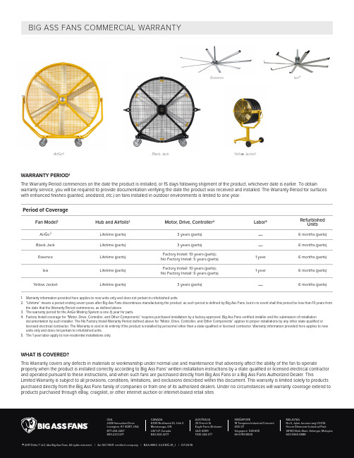
WARRANTY PERIOD 1The Warranty Period commences on the date the product is installed, or 15 days following shipment of the product, whichever date is earlier. To obtainwarranty service, you will be required to provide documentation verifying the date the product was received and installed. The Warranty Period for surfaces with enhanced finishes (painted, anodized, etc.) on fans installed in outdoor environments is limited to one year.WHAT IS COVERED?This Warranty covers any defects in materials or workmanship under normal use and maintenance that adversely affect the ability of the fan to operateproperly when the product is installed correctly according to Big Ass Fans’ written installation instructions by a state qualified or licensed electrical contractor and operated pursuant to these instructions, and when such fans are purchased directly from Big Ass Fans or a Big Ass Fans Authorized Dealer. ThisLimited Warranty is subject to all provisions, conditions, limitations, and exclusions described within this document. This warranty is limited solely to products purchased directly from the Big Ass Fans family of companies or from one of its authorized dealers. Under no circumstances will warranty coverage extend to products purchased through eBay, craigslist, or other internet auction or internet-based retail sites.AirGo ®Black Jack BIG ASS FANS COMMERCIAL WARRANTYPeriod of CoverageFan Model 1Hub and Airfoils 2Motor, Drive, Controller 4Labor 5RefurbishedUnitsAirGo 3Lifetime (parts) 3 years (parts)— 6 months (parts)Black Jack Lifetime (parts)3 years (parts)—6 months (parts)Essence Lifetime (parts)Factory Install: 10 years (parts);No Factory Install: 5 years (parts) 1 year 6 months (parts)Isis Lifetime (parts)Factory Install: 10 years (parts);No Factory Install: 5 years (parts)1 year6 months (parts)Y ellow JacketLifetime (parts)3 years (parts)—6 months (parts)1. Warranty information provided here applies to new units only and does not pertain to refurbished units.2. “Lifetime” means a period ending seven years after Big Ass Fans discontinues manufacturing the product, as such period is defined by Big Ass Fans, but in no event shall this period be less than 10 years from the date that the Warranty Period commences, as defined above.3. The warranty period for the AirGo Misting System is one (1) year for parts.4. Factory Install coverage for “Motor, Drive, Controller, and Other Components” requires purchased installation by a factory-approved, Big Ass Fans certified installer and the submission of installation documentation by such installer. The No Factory Install Warranty Period defined above for “Motor, Drive, Controller, and Other Components” applies to proper installations by any other state-qualified or licensed electrical contractor. The Warranty is void in its entirety if the product is installed by personnel other than a state-qualified or licensed contractor. Warranty information provided here applies to new units only and does not pertain to refurbished units.5. The 1 year labor apply to non-residential installations only.Yellow JacketIsis ®EssenceWHO IS COVERED?This Warranty extends to the original purchaser and subsequent owners, but only while the fan remains at the site of the original installation. This Warranty extends through the first installation of the fan and terminates if the fan is moved or reinstalled at a new location.WHAT WILL BIG ASS FANS DO?1. During the Warranty Period, Big Ass Fans will, at its option:a. Repair or replace the affected components of any defective product;b. Repair or replace the defective product; orc. Refund the price you paid for the product upon return of the product to Big Ass Fans, shipping and insurance prepaid.2. During the first 12 months of the Warranty Period, with purchase of factory installation for a commercial installation, Big Ass Fans will pay reasonable laborcosts, as defined below, for repairing or replacing a defective fan or any defective components of the fan at the installation location. Alternatively, Big Ass Fans may, at its option, require return of the fan to Big Ass Fans for repair or replacement.BIG ASS FANS WILL SHIP THE REPAIRED PRODUCT OR REPLACEMENT TO YOU AT NO CHARGE; HOWEVER, YOU ARE RESPONSIBLE FOR ALL COSTS OF REMOVAL, REINSTALLATION, AND SHIPPING OF THE PRODUCT TO THE BIG ASS FANS SERVICE CENTER.The foregoing constitutes your exclusive remedy and the limit of liability for Big Ass Fans, and for any and all losses in connection with this product.WHAT STEPS ARE REQUIRED TO OBTAIN WARRANTY SERVICE?1. If the fan is operating, immediately turn off the fan.2. Contact Big Ass Fans’ Technical Support Department as soon after the issue is discovered as possible by:a. Visiting the Big Ass Fans website and submitting a technical support form; orb. Calling the Technical Support phone number listed for your region.3. Once the Technical Support Representative has received your warranty claim, a case will be processed. In order to process this case, please have thefollowing information available:a. Y our name, address, phone number, and installation address;b. Product brand name, serial number, purchase price, and verification of product installation or premises possession date;c. Detailed description of the problem you have experienced.4. If the Technical Support Representative determines that the warranty claim is valid and that a replacement part is required, the Representative willprocess the claim and the replacement part will be shipped to you. Included in the shipment of the replacement part will be any shipping labels and documents needed to return the original part, including a Return Materials Authorization (RMA) number.Y our receipt of the replacement part constitutes your agreement to return the failed part to Big Ass Fans within 15 days of the receipt of the replacement part delivery. If Big Ass Fans does not receive the original part, you will be invoiced for the retail cost of the replacement part, and you will be responsible for payment for the replacement part upon receipt of the invoice. Big Ass Fans reserves all rights it retains under law to collect the retail cost of the replacement part if the original is not returned as specified above.5. Obtaining service may involve contacting a contractor to remove, repair, or replace the fan, or to remove the fan and return it to us. The cost of laborincurred, for factory installed fans, to remove, repair, or reinstall the fans will be covered only during the first 12 months after the warranty becomes effective, and only pursuant to the terms of the definition of “Labor” detailed in this Warranty.6. If we ask you to ship the fan back to Big Ass Fans for repairs or replacement, we will prepay the shipping and insurance for factory installed fans duringthe first 12 months after the warranty becomes effective; however, you will have to repackage the fan in such a way that there is no damage to the fan in transit. Y ou will be sent any return shipment documentation necessary to help you return the fan to Big Ass Fans. If we determine that no warrantable failure occurred or defect exists, we may invoice you for these shipping costs.Please be patient while we arrange for or undertake the necessary warranty service. We will provide you with regular status updates, as well as shipment dates, if appropriate, until your fan is back in service.CONDITIONS1. Big Ass Fans reserves the right to make the final determination, based on its own evaluation of the fan and all components, as to whether:a. The problem in question is the result of a defect in design, workmanship, or materials, and not a result of error, misuse, or abuse on the part of thecustomer as set forth under the exclusions detailed in this Warranty;b. Noise heard during operation is within normal operating levels, in which case this Warranty would be inapplicable. Note: Certain electrical, motor,or other operating noise may be impossible to eliminate due to the fan design and/or site conditions. Dissatisfaction with normal operating noise levels is not covered by this Warranty, and return of any fans for this reason will be subject to Big Ass Fans’ Return Policy (see below).c. Adverse site conditions, (including, but not limited to, excessive dust, heat, humidity, unstable electric service, or any other unknown or unforeseencondition that affects the proper operation of the products) improper application, or improper installation is determined to be the basis for the failure.d. The problem or defect is material and requires action under this Warranty; ande. The remedy of repair, replacement, or refund is appropriate.2. If Big Ass Fans determines, in its sole discretion, that the appropriate remedy under the Warranty is a refund, the refund amount will be limited to theprice paid by the customer for the product alone, and under no circumstances will it include the cost of labor, shipping, handling, packaging, or any other incidental or consequential costs incurred or anticipated by the customer.3. With respect to replacement or repair rendered, Big Ass Fans reserves the right to use replacement parts that are refurbished. Big Ass Fans warrantsthat the parts replaced or repaired, whether or not they have been refurbished or are original equipment, will operate properly and be free from defects in materials and workmanship for a period of 90 days from the date of shipment to the customer, or for the remainder of the original warranty period, whichever is longer.4. A service fee, parts replacement fee, and shipping charges may be imposed if any fan is returned for warranty service that is missing components orthat has been modified in any way. Such fees and charges will vary based upon the actual material and labor costs necessary to replace missing or modified parts and to return the fan to its original factory condition.RETURN POLICYReturns must be received within 90 days of shipment. The customer will be responsible for return freight charges. A restocking fee of 25% for unopened boxes and 50% for opened boxes applies to all returns.WHAT IS NOT COVERED?This warranty is only valid within Australia, Singapore, and Malaysia. No other written or oral warranties apply, and no employee, agent, dealer, or other person is authorized to give any warranties on behalf of Big Ass Fans.ATTENTION: Under no circumstances will the Big Ass Fans be responsible for remedial work necessary to correct installation procedures by others that do not conform to those established by the instructions, codes, and standards described under items 2 through 3.d below.1. Units purchased from any entity other than Big Ass Fans or a Big Ass Fans Factory Authorized Dealer.2. Units or components where the serial number or part number sticker has been removed or defaced.3. Defects, malfunctions, failure or physical damage caused by unauthorized service/parts and improper installation, adverse site conditions (including,but not limited to, excessive heat, dust or humidity, unstable electric service, or any other unknown or unforeseen condition that affects the proper operation of the products), mishandling, modifications, or damage while in your possession including failure to provide reasonable and necessary maintenance, which shall include, but not be limited to:a. Failure to follow the required installation procedures specified in the Big Ass Fans-supplied Installation Manual and in all other documentationsupplied with the fans and related equipment;b. Failure to follow all relevant codes and ordinances including, but not limited to, any applicable electric codes or similar codes and otherjurisdictional (including provinces and localities) local building codes;c. Failure to follow electrical engineering industry standards regarding the approved method of installing solid-state electrical equipment having thecharacteristics of the fan, the fan control, and their related components, even if such standards are not specifically referenced in any instructions or literature supplied by Big Ass Fans;d. Failure to use properly all installation and mounting hardware supplied by Big Ass Fans;e. Any modification or alteration of, or adjustment to the fans, fan control, and/or mounting and installation hardware and/or any disassembly of themajor components of the fans and fan controls for any purpose whatsoever, including any attempt to diagnose and/or repair any problem, without prior written authorization from Big Ass Fans’ Technical Support Department;f. Misuse, abuse, accidents, unreasonable use, or Acts of God;g. Incorrect electric current, voltage, or supply;h. Failure to use fan controls supplied by Big Ass Fans unless:i. Big Ass Fans’ Technical Support Department has provided written permission prior to installation; andii. The fan controls are built, operated, and maintained according to specifications provided to and approved by Big Ass Fans’ Technical Support Department.i. Failure to perform periodic maintenance as detailed in the Big Ass Fans-supplied installation manual.5. Consequential or incidental damages sustained by any person, entity, or structure as a result of any breach of these warranties, except where suchdamages may not be excluded by law.6. Claims made for products that have not been paid for in full.7. Damage caused by premises structural defects, structural movement or settlement, exposure to chemicals, salt water, acid rain or other corrosiveelements, excessive humidity, and/or wind.8. Normal changes to the finish caused by ordinary use or damage to non-factory applied finishes.9. Damage or failure caused by subjection of the product to conditions outside its design limitations.10. Defects reported more than 90 days from when they were discovered or should have been discovered.11. With regard to electrical and electronic components provided by Big Ass Fans that comprise part of the products, including motors, motor drives, andvariable frequency drives, Big Ass Fans relies on the determination by the original manufacturer as to whether the failure of such component was the result of a defect. If the manufacturer of such component determines that there was no defect and therefore refuses to cover it under warranty, Big Ass Fans likewise will not warranty such item unless Big Ass Fans determines that the failure of such electrical or electronic component was the result of a defect of design, workmanship, or material within some other part of the products.DEFINITIONS1. “Labor” shall mean on-site technical service provided by Big Ass Fans during the first year that the product is in service. At Big Ass Fans sole discretion,this may be employees of Big Ass Fans or qualified technicians contracted by Big Ass Fans. Big Ass Fans will not reimburse customers or independentcontractors without prior written approval from Big Ass Fans. Reimbursement will be limited to the Big Ass Fans customer in whose building the product(s) are installed of all reasonable cost paid by the customer to an independent contractor employed to remove, dismantle, reassemble, or reinstall any of the warrantied products during the first year that the product is in service. Big Ass Fans may request proof of payment by the customer to the independent contractor of all the charges, and will reimburse the customer only to the extent of those charges that are determined by Big Ass Fans, in its sole discretion, to be reasonable and necessary under the circumstances. Under no circumstances will labor apply to:a. Residential installations; andb. Installations where the product has been moved subsequent to its initial installation, unless not permanently installed (portable), or where any of theother warranty exclusions apply.2. “Operate properly” applies to mechanical, electrical, and structural functions only. No guarantee, unless and except by separate written agreement, ismade regarding the dimensions or air movement generated or the appropriateness of the effectiveness of any product for its intended purpose or for the customer’s particular application.ADDITIONAL RIGHTSThe benefits given to you under this warranty are in addition to and do not affect any other rights or remedies that you have under any law which relates to this product.THIS WARRANTY IS EXPRESSL Y IN LIEU OF ALL OTHER WARRANTIES, EXPRESSED OR IMPLIED, INCLUDING WARRANTIES OF MERCHANTABILITY OR FITNESS FOR PARTICULAR PURPOSE, AND OF ALL OTHER OBLIGATIONS AND LIABILITIES ON BIG ASS FANS’ PART, AND BIG ASS FANS NEITHER ASSUMES NOR AUTHORIZES ANY PERSON TO ASSUME FOR IT ANY OTHER LIABILITY IN CONNECTION WITH THE SALE OF THE PRODUCTS. NO OTHER WARRANTY, EXPRESSED OR IMPLIED, WHETHER OF FITNESS FOR A PARTICULAR PURPOSE OR OF MERCHANTABILITY OR OF ANY OTHER KIND, WHETHER OR NOT SIMILAR IN NATURE TO ANY PREVIOUSL Y SPECIFIED, SHALL EXIST WITH RESPECT TO SUCH PRODUCTS, ALL SUCH WARRANTIES BEING HEREBY DISCLAIMED BY BIG ASS FANS AND WAIVED BY CUSTOMER. UNDER NO CIRCUMSTANCES SHALL BIG ASS FANS COMPANY BE LIABLE FOR ANY LOSS, DAMAGE, COST OF REPAIR, OR INCIDENTAL OR CONSEQUENTIAL DAMAGES OF ANY KIND IN CONNECTION WITH THE USE, SALE, OR REPAIR OF ANY PRODUCTS PURCHASED FROM BIG ASS FANS, UNLESS SUCH DAMAGES CANNOT BE EXCLUDED BY LAW.Big Ass Fans reserves the right to change this warranty at any time without advance notice.。
Unitronics 1 SambaOPLC 平板触摸显示PLC系列技术参数及订购信息说明书
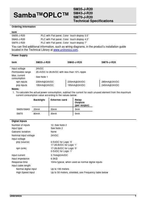
Samba™OPLC™ SM35-J-R20SM43-J-R20SM70-J-R20Technical SpecificationsOrdering InformationItemSM35-J-R20 PLC with Flat panel, Color touch display 3.5’’SM43-J-R20 PLC with Flat panel, Color touch display 4.3’’SM70-J-R20 PLC with Flat panel, Color touch display 7’’You can find additional information, such as wiring diagrams, in the product’s installation guide located in the Technical Library at .Power SupplyItem SM35-J-R20 SM43-J-R20 SM70-J-R20Input voltage 24VDCPermissible range 20.4VDC to 28.8VDC with less than 10% rippleMax. currentconsumptionSee Note 1npn inputs 235mA@24VDC 235mA@24VDC 285mA@24VDCpnp inputs 195mA@24VDC 195mA@24VDC 240mA@24VDCNotes:1. To calculate the actual power consumption, subtract the current for each unused element from the maximumcurrent consumption value according to the values below:Backlight Ethernet card RelayOutputs(per output)SM35/SM43 20mA 35mA 5mASM70 80mA 35mA 5mADigital InputsNumber of inputs 12. See Note 2Input type See Note 2Galvanic isolation NoneNominal input voltage 24VDCInput voltagepnp (source) 0-5VDC for Logic ‘0’17-28.8VDC for Logic ‘1’npn (sink) 17-28.8VDC for Logic ‘0’0-5VDC for Logic ‘1’Input current 3.7mA@24VDCInput impedance 6.5KΩResponse time 10ms typical, when used as normal digital inputsInput cable lengthNormal digital input Up to 100 metersHigh Speed Input Up to 50 meters, shielded, see Frequency table below2/15 Samba™ OPLC™High speed inputs Specifications below apply when wired as HSC/shaft-encoder.See Note 2Frequency (max) See Note 3Cable length (max.) HSC Shaft-encoder pnp Shaft-encoder npn10m 30kHz 20kHz 16kHz25m 25kHz 12kHz 10kHz50m 15kHz 7kHz 5kHz Duty cycle 40-60%Resolution 32-bitNotes:2. This model comprises a total of 12 inputs. Input functionality can be adapted as follows.All 12 inputs may be used as digital inputs. They may be wired in a group via a single jumperas either npn or pnp.In addition, according to jumper settings and appropriate wiring:- Inputs 5 and 6 can function as either digital or analog inputs.•If the digital inputs function as npn, analog option is not available.- Input 0 can function as a high-speed counter, as part of a shaft-encoder,or as normal digital inputs.- Input 1 can function as either counter reset, normal digital input, or as part of a shaft-encoder.- If input 0 is set as a high-speed counter (without reset), input 1 can functionas a normal digital input.3. pnp/npn maximum frequency is at 24VDC.Analog InputsNumber of inputs 2, according to wiring as described above in Note 2Input type Multi-range inputs: 0-10V, 0-20mA, 4-20mAInput range 0-20mA, 4-20mA 0-10VDCInput impedance 243Ω>150KΩMaximum input rating 25mA, 6V 15VGalvanic isolation NoneConversion method Successive approximationResolution (except 4-20mA) 10-bit (1024 units)Resolution (at 4-20mA) 204 to 1023 (820 units)Conversion time One configured input is updated per scan. See Note 4Precision 0.9%Status indication Yes – if an analog input deviates above the permissible range,its value will be 1024.Note:4. For example, if 2 inputs are configured as analog, it takes 2 scans to update all analog values.SMxx-J-R20 Technical Specifications 2/15Digital OutputsNumber of outputs 8 relay (in 2 groups). See Note 5Output type SPST-NO (Form A)Isolation By relayType of relay Tyco PCN-124D3MHZ or compatibleOutput current (resistive load) 3A maximum per output8A maximum total per commonRated voltage 250VAC / 30VDCMinimum load 1mA, 5VDCLife expectancy 100k operations at maximum loadResponse time 10ms (typical)Contact protection External precautions required (see Increasing Contact Life Span in theproduct’s Installation Guide)Note:5. Outputs 0, 1, 2 and 3 share a common signal. Outputs 4, 5, 6, and 7 share a common signal.Graphic Display ScreenItem SM35-J-R20 SM43-J-R20 SM70-J-R20 LCD Type TFT, LCD display TFT, LCD display TFT, LCD display Illumination backlight White LED White LED White LED Display resolution 320x240 pixels 480x272 pixels 800x480 pixels Viewing area 3.5" 4.3" 7"Colors 65,536 (16-bit) 65,536 (16-bit) 65,536 (16-bit) Touchscreen Resistive, analog Resistive, analog Resistive, analog Screen brightness control Via software (Store value to SI 9, values range: 0 to 100%)Virtual Keypad Displays virtual keyboard when the application requires data entry.ProgramItem SM35-J-R20 SM43-J-R20 SM70-J-R20 Memory sizeApplication Logic 112KB 112KB 112KBImages 1MB 2MB 5MBFonts 512KB 512KB 512KBOperand type Quantity Symbol ValueMemory Bits 512 MB Bit (coil)Memory Integers 256 MI 16-bit signed/unsignedLong Integers 32 ML 32-bit signed/unsignedDouble Word 32 DW 32-bit unsignedMemory Floats 24 MF 32-bit signed/unsignedFast Bits 64 XB Fast Bits (coil) – not retainedFast Integers 32 XI 16 bit signed/unsigned (fast, not retained)Fast Long Integers 16 XL 32 bit signed/unsigned (fast, not retained)Fast Double Word 16 XDW 32 bit unsigned (fast, not retained)Timers 32T Res. 10 ms; max 99h, 59 min, 59.99sCounters 16 C 32-bitData Tables 32K dynamic data (recipe parameters, datalogs, etc.)16K fixed data (read-only data, ingredient names, etc)HMI displays Up to 24Program scan time 15µs per 1kb of typical application2/15 Samba™ OPLC™Communication PortsPort 1 1 channel, RS232 (SM35) , USB device (SM43/SM70)Galvanic isolation SM35 and SM43 – NoSM70 - YesBaud rate 300 to 115200 bpsRS232 (SM35 only)Input voltage ±20VDC absolute maximumCable length 15m maximum (50’)USB device (SM43,SM70 only)Port type Mini-BSpecification USB 2.0 complaint; full speedCable USB 2.0 complaint; up to 3mPort 2 (optional) See Note 6CANbus (optional) See Note 6Notes:6. The user may order and install one or both of the following modules:- A serial RS232/RS485 isolated/non-isolated interface module, or an Ethernet Interface module in port 2.- A CANbus modulemodules documentation is available on the Unitronics website.MiscellaneousClock (RTC) Real-time clock functions (date and time)Battery back-up 7 years typical at 25°C, battery back-up for RTC and system data, includingvariable dataBattery replacement Yes. Coin-type 3V, lithium battery, CR2450DimensionsItem SM35-J-R20 SM43-J-R20 SM70-J-R20Size 109 x 114.1 x 68mm(4.29 x 4.49 x 2.67”).See Note 7 136 x 105.1 x 61.3mm(5.35 x 4.13 x 2.41”).See Note 7210 x 146.4 x 42.3mm(8.26 x 5.76 x 1.66”).See Note 7Weight 210g (7.4 oz) 350g (12.34 oz) 640g (22.57 oz) Notes:7. For exact dimensions, refer to the product’s Installation Guide.EnvironmentOperational temperature 0 to 50ºC (32 to 122ºF)Storage temperature -20 to 60ºC (-4 to 140ºF)Relative Humidity (RH) 10% to 95% (non-condensing)Mounting method Panel mounted (IP65/66/NEMA4X)DIN-rail mounted (IP20/NEMA1)Operating Altitude 2000m (6562 ft)Shock IEC 60068-2-27, 15G, 11ms durationVibration IEC 60068-2-6, 5Hz to 8.4Hz, 3.5mm constant amplitude,8.4Hz to 150Hz, 1G acceleration.SMxx-J-R20 Technical Specifications 2/15 The information in this document reflects products at the date of printing. Unitronics reserves the right, subject to all applicable laws, at any time, at its solediscretion, and without notice, to discontinue or change the features, designs, materials and other specifications of its products, and to either permanently ortemporarily withdraw any of the forgoing from the market.All information in this document is provided "as is" without warranty of any kind, either expressed or implied, including but not limited to any implied warranties of merchantability, fitness for a particular purpose, or non-infringement. Unitronics assumes no responsibility for errors or omissions in the information presented inthis document. In no event shall Unitronics be liable for any special, incidental, indirect or consequential damages of any kind, or any damages whatsoever arising out of or in connection with the use or performance of this information.The tradenames, trademarks, logos and service marks presented in this document, including their design, are the property of Unitronics (1989) (R"G) Ltd. or other third parties and you are not permitted to use them without the prior written consent of Unitronics or such third party as may own them.DOC17018-A5 02/15。
易维斯 泽尼斯 热升华塑料卡打印机操作手册说明书

FLEXIBILITY• W ith Zenius, you can choose to insert your cards individually or with the automatic feeder.• T he «Expert» version of Zenius features combinable encoding functions: magnetic encoding, contact and contactless chips. It takes just a few minutes to install these modules!EASE OF USE• W ith the Evolis Premium Suite ®software, you can receive notifications and easily control the printer from your computer.• E volis High Trust ® ribbons are easy to install and automatically recognized and set by the printer.SMALL FOOTPRINT• H ardly larger than a standard sheet of paper, Zenius fits perfectly into any environment, be it the office or a customer service counter.• Z enius is an eco-designed printer: very efficient sleep mode and low energy consumption.The Zenius printer is designed for single sided printing and encoding of a very large variety of plastic cards. Zenius generates color or monochrome cards, individually or in small runs, with top quality results. Zenius is a user-friendly, compact and cost-effective solution for delivering your personalized cards.ZENIUSTHE COMPACT AND AGILE CARD PRINTER©2015 Evolis. All rights reserved. Actual product(s) may differ from information stated in this document. All specifications or pictures are subject to change without prior notice. All trademarks mentioned herein belong to their respective owners. Pictures: Olivier Calvez. 07/2015. KB-ZEN1-064-ENG-A4 Rev D0. MK000494EUROPE - MIDDLE-EAST - AFRICAEvolis - 14 avenue de la Fontaine - ZI Angers-Beaucouzé 49070 Beaucouzé - FranceT +33 (0) 241 367 606 - F +33 (0) 241 367 612 - info @AMERICAS - Evolis Inc. - Fort Lauderdale - evolisinc @ ASIA-PACIFIC - Evolis Asia Pte Ltd - Singapore - evolisasia @ CHINA - Evolis China - Shanghai - evolischina @ INDIA - Evolis India - Mumbai - evolisindia @MANUAL OR AUTOMATIC CARD FEEDERGENERAL FEATURES• Direct-to-card dye-sublimation/Resin thermal transfer • Single-sided printing, edge-to-edge • 300 dpi print head (11.8 dots/mm)• 16 million colors• 16 MB memory (RAM)PRINTING PERFORMANCES• C olor (YMCKO): 120 - 150 cards/hour 1• Monochrome: 400 - 500 cards/hourINTERFACES• U SB (1.0, 1.1, 2.0, 3.0), cable supplied • E thernet TCP-IP 10BaseT, 100BaseT (Traffic Led) on the Expert versionCARD MANAGEMENT AND SPECIFICATIONS• A utomatic or manual feeding• Feeder capacity: 50 cards (0.76 mm – 30 mil)• O utput hopper capacity: 20 cards (0.76 mm – 30 mil)• C ard thickness: 0.25 to 0.76 mm (10 to 30 mil), gauge adjustment • C ard types: PVC cards, composite PVC cards, PET cards, ABS cards 1, special varnished cards 1• C ard format: ISO CR80 - ISO 7810 (53.98 mm x 85.60 mm)OPTIONAL FEATURES• C olors available: fire red & grey brown• E xpert version: Ethernet TCP-IP, encoding modules as optionsADDITIONAL ENCODING MODULES•A vailable modules:- Magnetic stripe encoder ISO 7811 HiCo/LoCo, JIS2 - Smart contact station ISO 7816-2- Contact smart card encoder - PC/SC, EMV 2000-1- C ontactless smart card encoder - ISO 14443A, B, ISO15693, MIFARE, DESFire, HID iCLASS - Other specific encoders upon request • I nternal USB or IP ports • O ptions can be combined • F actory-installed or installed on siteSAFETY• S upport for Kensington ® security lock • D ata encryption for magnetic encodingDISPLAY•P rinter LEDs• G raphical notifications from the printer 2: cleaning alerts, empty/low level ribbon and card alerts, etc.EVOLIS HIGH TRUST ® RIBBONSTo maximize the quality and durability of printed cards, the lifespan of the print head and the overall printer reliability, use Evolis High Trust ® ribbons.• A utomatic identification and setting • D elivered in a drop-in cassette for easy handling • R ibbon saver for monochrome printing List of ribbons available on SOFTWARE• D elivered with Evolis Premium Suite ® for Windows ®:- Printer driver - E volis Print Center for administration and settings - Evolis Printer Manager for graphical notification 3 - 24/7 online support - C ompatible with Windows ® (32/64 bits): XP SP3, Vista, W7, W8, W10• D elivered with cardPresso XXS Lite for designing and editing badges:- Internal database up to 50 records- Windows ® (from XP onwards) and Mac OS X • D elivered with a driver for Mac OS X (from 10.5 onwards)• L inux OS upon request • E volis Premium SDK for remote supervision of the printer, while facilitating and speeding up integration into IT systemsECO-FRIENDLY DESIGN, CERTIFICATIONS AND STATEMENT OF COMPLIANCE• S tandby, sleep modes & reduced energy consumption • C E, FCC, IEC, VCCI, CCC, KC, BIS, EAC •R oHSSIZE AND WEIGHT• S ize (H x W x D): 195 x 205 x 315 mm (7.68’’ x 8.07’’ x 12.4’’)• W eight: 3.3 kg (7.3 lbs)WARRANTY• 2-year warranty (printer and print head)4• W arranty extension available as an optionMAIN FEATURES / Full technical specifications on Easy handling, automatic ribbonrecognition and setupW eight: 3.3 kg (3.64 lbs)315 mm (12.4’’)195 mm (7.68’’’)205 mm (8.07’’)1 Under specific conditions /2 Depends on the Windows version /3 Requires the .net 4.0 client profile version4 Warranty subject to observance of specific conditions and use of Evolis High Trust ribbonsALC Technologies Pte LtdBlk 998 Toa Payoh North #07-07/08/09318993 Singapore SingaporeTel : 63541650Fax : 63544595E-mail:*******************Web : 。
工写斯特 工位中心 产品说明书
color & trIm oPtIonsHeight Adjustable WorkcentersT ask LightingMonitor ArmsAdjustable Keyboard Platforms159159Color & Trim Options160Silhouette Edge ProfilesErgoS1BlockS2CraftS3Height Adjustable Workcenters: Laminate ColorsClassic Collection–Workrite Sierra HX, HXL and ProliftixFolkstone GraySG241Opti GraySG213BlackSE101Ice FishinWF181White SpectrumAW785Gateway to the FutureAV100Cavalcade SouthAT650Tropical GetawayAV110Summer Heat WaveAO360IL Palio PapelAV981Coriander FiberAT981Leave LikatreWP120Looks LikatreWP110Appears LikatreWP115Seems LikatreWP125Hardrock MapleWM791PearwoodWX031Shaker CherryWC521Oiled CherryWC421Jewel MahoganyWY351Black AshwoodSZ101Silhouette Collection–Workrite Sierra HX & HXLHardrock Maplewith brown coreWM791Appears Likatrewith brown coreWP115Seems Likatrewith brown coreWP125Oiled Cherrywith brown coreWC421Folkstone Graywith black coreSG241White Spectrumwith black coreAW785Looks Likatrewith black coreWP110Blackwith black coreSE101All Silhouette worksurfaces are made of GREENGUARD® certified material.Color & Trim Options161 800.959.9675Note: Due to printing limitations, colors are not guaranteed to be accurately reproduced. For best results, refer to actual finish samples available from your Workrite sales representativeor by calling 1.800.959.9675Lead Times:Classic Collection: 10 working days for quantity 20 or less.Designer Collection: 20 working days for quantity 10 or less.Silhouette Collection: 10 working days for quantity 10 or less.Height Adjustable Workcenters: Metal Finishes & Trim OptionsMetal FinishesSierra HX and HXLProliftixSierra Silver SCharcoal CEdge Treatments for Classic & Designer LaminatesStandardWedgeRippleBlack 07Height Adjustable Workcenters: Laminate Colors (cont.)Designer Collection–Workrite Sierra HX and HXLSpa White S740T Almond ST655Putty Gray SG209Taupe ST606Sage SV720Cubicle Papel AG561Gray Santos AG291Negotiating in Geneva PFA60Beige Crepe AT251Opti Gray Crepe AG341Vanilla Fiber AW871Wheat Fiber AT991Oatmeal Fiber AT101Thyme Fiber AV721Pepper Fiber AG581Manila Linen AT231Gridlock in LA PFA51Travlin Light AT680Gold Pannin AT710Passin Through AV250Blue Sandstone AB191Caramel Crepe AT111Amber Raffia II AO355Brick by Brick AR350Anigre WX041Millwork Cherry WC431Honey Maple WM951Yorkshire Cherry WC411Moroccan Fresco AT121Sipping Seattle Java PFA48Color & Trim Options162Adjustable Keyboard PlatformsGlide 2All OthersPlatform Palm Support PlatformPalm SupportCharcoalCCool GrayGCharcoal11Cool Gray12BLight GrayG25Dove Gray26Monitor ArmsWillowWorkrite Poise, SwingArm & SteadyArmSilverSGraphiteBSilverSTask LightingDazz—SL Fino, Verano & AstraLincolnD1N1N2G1G2G4W1CSterlingS WSilverSNote: Due to printing limitations, colors arenot guaranteed to be accurately reproduced.For best results, refer to actual finish samplesavailable from your Workrite sales representativeor by calling 1.800.959.9675 Height Adjustable Workcenters: Sierra Modesty PanelFabric ColorSierra HX, HXL and ProliftixWhite01Pearl02Bronze03Dove04Linen05Pewter06Charcoal07。
WT_SOM9854_S1核心板说明书(1)

WT_SOM9854_S1核心板说明书(1)WT_SOM9854_S1 核心板说明书深圳市启明云端科技深圳市海创超能科技一.产品介绍WT_SOM9854_S1是一款搭载智慧触控型SOC IT9854E的邮票孔封装核心板产品. SOC内置3个CPU( ARM9 400MHZ + 2* RISC 200MHZ) ,内置64MB DDRII, 支持最大1280*800 24bit LCD显示屏, 支持720P H.264 视频硬件解码, 2D硬件绘图引擎,JPEG和音频硬件编解码引擎. 丰富的外围接口包括: 10/100M以太网接口, USB*2, SPI*2, UART*4, PWM*6, SD/MMC *1, IIC *2 , IIS*1, MAC*1, CSI*1等.WT_SOM9854_S1核心板实物图片WT_SOM9854_S1工业级核心板, 具有极低的成本和极高的性能,适用于以下行业和产品: ●大型家电,如触控式洗衣机,空调,冰箱等.●厨房家电,如触控式烤箱,微波炉,咖啡机,饮水机等.●运动器材,如跑步机按摩椅等触控显示.●工业控制,如电梯, UPS, 电子称和工业触摸设备.●其他HMI (人机界面)的触控设备.WT_SOM9854_S1工业级核心板的主要特点:◆易于使用,方便客户快速定制产品, 核心板处理了SOC的PDN,晶体,SPI FLASH等敏感和通用电路,只需要提供5V供电即可稳定工作.◆核心板对外提供3.3V@1A电源输出,底板无须单独设3.3V逻辑用电,避免系统上电时序错误和电流回灌等问题.◆超小封装: 35mm*35mm , 1.27mm 间距邮票孔.◆严格优化和测试的电源完整性设计和信号完整性设计.◆核心板可选屏蔽罩,背面无任何信号走线,可最优化最终产品的EMI/EMC性能.◆大厂四层PCB, 沉金工艺, 品质保证.◆长期批量稳定出货, 为中小批量客户降低生产和供货风险,节省成本.二.应用说明2.1 WT_SOM9854_S1 核心板的系统结构:WT_SOM9854_S1 系统结构示意图2.2 基于WT_SOM9854_S1 核心板的应用电路设计:基于WT_SOM9854_S1的典型应用电路2.3 电路设计要点:1)供电输入: *******, 去耦电容至少100uF,选用低ESR钽电容或者铝电解电容+22uFMLCC并联放置, 去耦电容靠近核心板供电引脚放置.2) 3.3V输出: 核心板输出3.3V@1A , 与核心板共用3.3V电压. 输出引脚通过磁珠(3A电源型)和电容构成π型滤波或者LC滤波电路. 使得核心板与底板3.3V 不产生相互干扰. 滤波电容至少22uF MLCC.3)底板所有与核心板互连的IC的3.3V逻辑电平应使用核心板3.3V 输出. 底板其他电源应在3.3V供电输出后使能供电.4)核心板所有GND引脚, 与底板GND平面充分连接, 以最小感抗路径返回电源GND.5)LCD 数字RGB接口, 24bit RGB, HS, VS , DE, PCLK信号线在靠近核心板引脚处串接端接电阻,22R~33R. 其他高速走线如SPI, SDIO, IIS等类似处理,串联端接电阻请靠近驱动端引脚放置.6)USB差分线差分阻抗控制在90 ohm ±10%, 其余单端信号线阻抗控制在50 ohm±10% .7)LCD, 高速SPI, SDIO, IIC, CSI总线应按组等长走线,等长容限±200mil .三.W T_SOM9854_S1 引脚定义WT_SOM9854_S1核心板引脚定义* 说明:1.HOST_CFG[1:0],上拉或者下拉10K电阻,决定SOC的启动模式,配置定义:01 – SPI FLASH 启动11 – USB2SPI下载模式HOST_CFG0默认设计为上拉. 通过控制HOST_CFG1上下拉切换FLASH启动模式或者下载模式.2.PLL_CFG , DCXO_CFG 核心板已经放置了默认的下拉电阻, 底板上请勿引入改变引脚上电期间默认电平的电路,如各种直接或者间距拉高该引脚的电路.3.GPIO0~GPIO4 为调试下载相关引脚,应避免用于其他用途.4.SDDAT0~SDDAT2 在核心板上已经作为SPI0连接SPI NOR FLASH . 可以复用连接SD卡, 请参考评估板电路!5.UART1~UART3 TXD/RXD引脚可以配置在任意GPIO引脚上,但请避开上述特殊用途引脚!四.封装结构24 x 4 = 96 Pins , 35mmX35mmPin Pitch = 1.27 mm详细尺寸如下: (单位mm)。
Ergotron 1 of 9888-45-334-W-01 四脚架桌面LCD臂说明书
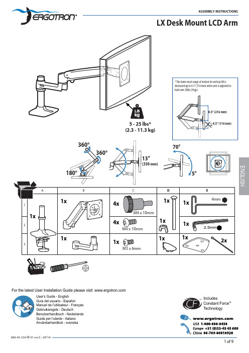
User's Guide - English Guía del usuario - EspañolManuel de l’utilisateur - Français Gebruikersgids - DeutschBenutzerhandbuch - Nederlands Guida per l’utente - Italiano Användarhandbok - svenska 用户指南 : 汉语IncludesConstant Force ™TechnologyFor the latest User Installation Guide please visit: These symbols alert users of a safety condi-tion that demands attention. All users should be able to recognize and understand the signi fi cance of the following Safety Hazards if encountered on the product or within the documentation. Children who are not able to recognize and respond appropriately to Safety Alerts should not use this product with-out adult supervision!Hazard Symbols ReviewSafetyImportant! You will need to adjust this product after installation is complete. Make sure all your equipment is properly installed on the product before attempting adjustments. This product should move smoothly and easily through the full range of motion and stay where you set it. If movements are too easy or dif fi cult or if product does not stay in desired positions, follow the adjustmentinstructions to create smooth and easy movements. Depending on your product and the adjustment, it may take many turns to notice a difference. Any time equipment is added or removed from thisproduct, resulting in a change in the weight of the mounted load, you should repeat these adjustment steps to ensure safe and optimum operation.enough to handle mounted product and equipment.Caution:To avoid the potential to pinch cables it is important to follow the cable routing instructions in this manual. Failure to follow these instructions may result in equipment damage or personal injury.12WARNING! Stored Energy Hazard: The arm mechanism is under tension and will move up rapidly, on its own, assoon as attached equipment is removed. For this reason, DO NOT remove equipment unless the arm has beenmoved to the highest position! Failure to follow this instruction may result in serious personal injury and/orequipment damage!3ENGLISH6360°0°dRotate – Portrait/LandscapeFor local customer care phone numbers visit: Learn more about ergonomic computer use at:Set Your Workstation to Work For YOU!Height Position top of screen slightly below eye level.Position keyboard at about elbow height with wrists fl at.Distance Position screen an arm's length from face—at least 20” (508mm).Position keyboard close enough to create a 90˚ angle in elbow. Angle Tilt screen to eliminate glare.Tilt the keyboard back 10° so that your wrists remain fl at.To Reduce FatigueBreathe - Breathe deeply through your nose.Blink - Blink often to avoid dry eyes.Break • 2 to 3 minutes every 20 minutes• 15 to 20 minutes every 2 hours.。
- 1、下载文档前请自行甄别文档内容的完整性,平台不提供额外的编辑、内容补充、找答案等附加服务。
- 2、"仅部分预览"的文档,不可在线预览部分如存在完整性等问题,可反馈申请退款(可完整预览的文档不适用该条件!)。
- 3、如文档侵犯您的权益,请联系客服反馈,我们会尽快为您处理(人工客服工作时间:9:00-18:30)。
WT_SOM9854_S1 核心板说明书
深圳市启明云端科技
深圳市海创超能科技
一.产品介绍
WT_SOM9854_S1是一款搭载智慧触控型SOC IT9854E的邮票孔封装核心板产品. SOC内置3个CPU( ARM9 400MHZ + 2* RISC 200MHZ) ,内置64MB DDRII, 支持最大1280*800 24bit LCD显示屏, 支持720P H.264 视频硬件解码, 2D硬件绘图引擎,JPEG和音频硬件编解码引擎. 丰富的外围接口包括: 10/100M以太网接口, USB*2, SPI*2, UART*4, PWM*6, SD/MMC *1, IIC *2 , IIS*1, MAC*1, CSI*1等.
WT_SOM9854_S1核心板实物图片
WT_SOM9854_S1工业级核心板, 具有极低的成本和极高的性能, 适用于以下行业和产品: ●大型家电,如触控式洗衣机,空调,冰箱等.
●厨房家电,如触控式烤箱,微波炉,咖啡机,饮水机等.
●运动器材,如跑步机按摩椅等触控显示.
●工业控制,如电梯, UPS, 电子称和工业触摸设备.
●其他HMI (人机界面)的触控设备.
WT_SOM9854_S1工业级核心板的主要特点:
◆易于使用,方便客户快速定制产品, 核心板处理了SOC的PDN,晶体,SPI FLASH等敏感和通
用电路,只需要提供5V供电即可稳定工作.
◆核心板对外提供3.3V@1A电源输出,底板无须单独设3.3V逻辑用电,避免系统上电时序
错误和电流回灌等问题.
◆超小封装: 35mm*35mm , 1.27mm 间距邮票孔.
◆严格优化和测试的电源完整性设计和信号完整性设计.
◆核心板可选屏蔽罩,背面无任何信号走线,可最优化最终产品的EMI/EMC性能.
◆大厂四层PCB, 沉金工艺, 品质保证.
◆长期批量稳定出货, 为中小批量客户降低生产和供货风险,节省成本.
二.应用说明
2.1 WT_SOM9854_S1 核心板的系统结构:
WT_SOM9854_S1 系统结构示意图
2.2 基于WT_SOM9854_S1 核心板的应用电路设计:
基于WT_SOM9854_S1的典型应用电路
2.3 电路设计要点:
1)供电输入: 5V@1.5A , 去耦电容至少100uF,选用低ESR钽电容或者铝电解电容+22uF
MLCC并联放置, 去耦电容靠近核心板供电引脚放置.
2) 3.3V输出: 核心板输出3.3V@1A , 与核心板共用3.3V电压. 输出引脚通过磁珠(3A
电源型)和电容构成π型滤波或者LC滤波电路. 使得核心板与底板3.3V 不产生相互干扰. 滤波电容至少22uF MLCC.
3)底板所有与核心板互连的IC的3.3V逻辑电平应使用核心板3.3V输出. 底板其他电
源应在3.3V供电输出后使能供电.
4)核心板所有GND引脚, 与底板GND平面充分连接, 以最小感抗路径返回电源GND.
5)LCD 数字RGB接口, 24bit RGB, HS, VS , DE, PCLK信号线在靠近核心板引脚处串接端
接电阻,22R~33R. 其他高速走线如SPI, SDIO, IIS等类似处理,串联端接电阻请靠近驱动端引脚放置.
6)USB差分线差分阻抗控制在90 ohm ±10%, 其余单端信号线阻抗控制在50 ohm
±10% .
7)LCD, 高速SPI, SDIO, IIC, CSI总线应按组等长走线,等长容限±200mil .
三.W T_SOM9854_S1 引脚定义
WT_SOM9854_S1核心板引脚定义
* 说明:
1.HOST_CFG[1:0],上拉或者下拉10K电阻,决定SOC的启动模式, 配置定义:
01 – SPI FLASH 启动
11 – USB2SPI下载模式
HOST_CFG0默认设计为上拉. 通过控制HOST_CFG1上下拉切换FLASH启动模式或者下载模式.
2.PLL_CFG , DCXO_CFG 核心板已经放置了默认的下拉电阻, 底板上请勿引入改变引
脚上电期间默认电平的电路,如各种直接或者间距拉高该引脚的电路.
3.GPIO0~GPIO4 为调试下载相关引脚,应避免用于其他用途.
4.SDDAT0~SDDAT2 在核心板上已经作为SPI0连接SPI NOR FLASH . 可以复用连接SD卡, 请
参考评估板电路!
5.UART1~UART3 TXD/RXD引脚可以配置在任意GPIO引脚上,但请避开上述特殊用途引脚!
四.封装结构
24 x 4 = 96 Pins , 35mmX35mm
Pin Pitch = 1.27 mm
详细尺寸如下: (单位mm)。