MT05 台架标定手册V03解析
作业五号平台设备及操船手册

胜利作业五号平台概述1.平台基本信息平台名称:胜利作业五号平台型式:齿轮齿条升降的三腿自升式修井作业平台业主:中国石化集团胜利石油管理局井下作业公司国籍:中国注册港籍:东营港入级:CCS入级符号:★ CSA Self-elevating Work Over Unit,HELDK2.设计与建造设计方:胜利石油管理局钻井工艺研究院海洋所建造方:胜利石油化工建设有限责任公司竣工日期:2010年7月3.平台型式及功能a)平台型式胜利作业五号平台该平台是一艘齿轮齿条升降的三腿自升式修井作业平台,钢质非自航。
由平台主体、桩腿(带桩靴)、升降系统三部分组成。
平台主体平面形状接近三角形,三根圆柱形桩腿成艉二艏一布局,桩靴为八边形。
平台主甲板尾部布置有悬臂梁系统,平台首部设有四层生活楼和直升飞机平台。
b)平台功能平台的主要任务是对水深5~25m范围内的油井进行修井作业。
4.设计原则1)按CCS规范设计,入CCS级;2)平台稳性满足油田内移位和风暴拖航的要求;3)先进性与适用性相结合的原则;4)可靠性、安全性与创新性相结合的原则;5)结构设计优化的原则;6)配套设施操作维护方便的原则;7)生活设施完善舒适的原则;8)满足HSE(健康、安全、环保)要求。
5.适用范围1)本平台适用于4500 m深度内的直、斜井的大修、小修作业(用3—1/2〞钻杆)。
2)作业范围:渤海湾水深5~25 m(含天文潮和风暴潮)内泥砂质海底的海域或相类似海域。
3)平台为无冰期作业。
1.1 主要指标及性能6.平台坐标系为了更好的描述本平台,在本手册中给出坐标系。
坐标系原点位于平台中心线尾端基线处,X轴向首为正,Y轴向左舷为正,Z轴向上为正。
特别注意:在本手册的计算过程中,计算数据都应为该坐标系中的数据。
图 1 平台坐标系7.主要设计指标表 1 主要参数表说明:○1许用钻台最大可变载荷组合:指钻台立根盒油管重量、大钩载荷、转盘载荷以及钻台其他活动件重量的组合。
高标定台架标定介绍完整版

高标定台架标定介绍 HEN system office room 【HEN16H-HENS2AHENS8Q8-HENH1688】标定技术介绍绪论标定的必要性电控柴油机为了满足工程目标,在满足严格排放的前提下,获得有竞争力的燃油经济性指标和高可靠性的要求。
电控软件中所有的变量都是可调的,将所有变量赋予优化值的过程称之为标定。
可以通过标定最大限度地发挥柴油机潜力,达到追求的工程目标。
因为赋予了更大的灵活性和可调性,标定很差的发动机性能甚至会比机械泵发动机还差。
相对汽油机的标定,柴油机的标定难度更高更具挑战性。
柴油机的压燃式燃烧,与喷油器、增压器、气道以及配气机构等参数息息相关,而标定只能控制燃油喷射,标定工作是柴油机性能和排放开发的重点工作内容。
柴油机的标定必须与燃烧系统开发同步进行。
标定的基本概念发动机电控系统的标定工作是电控发动机应用开发的一个重要阶段。
研发人员之所以要对电控系统进行标定,其原因在于发动机电控工作过程的复杂性,而这种复杂性具体体现在如下方面:(1)发动机电控系统需要实现众多的控制项目,如控制起动、怠速、调速等运行工况;(2)发动机电控系统的控制要使发动机的潜力充分发挥,使功率、油耗、排放和汽车操纵性等多方面的性能达到综合最佳的状态;(3)影响发动机性能的因素众多、变动范围大,如发动机的负荷与转速、冷却液的温度、进气温度、燃油温度、机油温度、增压压力等,电控系统对所有这些因素的变化都要作出相应的调整;(4)发动机电控系统必须适应复杂的外界环境变化,如季节变化以及海拔高度的变化等等。
从控制技术的角度来看,发动机是一个动态、多变量、高度非线性、具有响应滞后的时变系统,其工作过程包含十分复杂的动力学、热力学、流体力学、化学反应动力学等过程。
正是由于发动机系统严重的非线性等原因,一方面,采用经典的线性控制理论来控制参数优化值的方法已不可能。
另一方面,通过实时计算求得的控制参数值的方法,在目前的硬件技术上也是根本不可能满足的,所以在开发电控发动机时,只能先通过大量的试验,把所获得的各种工况下的动力性、燃油经济性、以及排放性能等试验数据,按照一定的优化准则和相关法规的要求,采取适当的优化方法,最终获得的控制参数和各种修正参数随发动机转速和负荷等因素变化的规律,并采用三维图、二维曲线等方式,把按照这种规律变化的控制参数值存贮在电控单元中,即所谓的MAP图。
MT-3505产品安装说明书
INSTALLATION OVERVIEW:_____________________________________________These installation instructions are for the MT-3505. Some parts are shipped separately and need to be installed before the unit can be used. These parts are listed below in the parts and accessories list.Please follow the installation instructions below and then perform the checkout procedure to ensure the unit is operating properly.PARTS & ACCESSORIES LIST FOR:______________________________________PART NUMBER DESCRIPTION QTY 1-5680BARB FITTING 12-5857CABLE CLAMP 12-7551FUSE, 1 AMP16-2421AC POWER CORD10301-0944-01PRIMARY FILTER ELEMENT, 75 MICRON 10301-0945-01SECONDARY FILTER ELEMENT, 8 MICRON 10692-1834-01QUALITY CONTROL QUESTIONNAIRE 17049-0130-01NO CELL1MT60A08A TACHOMETER PICKUP ASSEMBLY 1MT3000210A DC POWER LEAD SET ASSEMBLY 17049-0004-01O 2 CELL1MT310018EXHAUST PROBE TIP 1MT310020EXHAUST HOSE1MT310032EXHAUST PROBE LEAK CHECK CAP 1MT310047EXHAUST PROBE HANDLE1MT350090TACHOMETER ADAPTER LEAD 1SC33REGISTRATION CARD 1SF327WARRANTY CERTIFICATE 1ZMT3505OPERATORS MANUAL1REQUIRED TOOLS:____________________________________________________• STANDARD TOOL KITINSTALLATION INSTRUCTIONS:_________________________________________NOTE:FOR THE FOLLOWING INSTALLATION INSTRUCTIONS PLEASE REFER TO FIGURE 1.Model:MT-3505UNIT SETUP Page:1 of 31. Remove the MT-3505, and accessories box, from the carton it was shipped in. Discard allpackaging material.2. Remove the tag from the AC line filter / fuse assembly.3. Open the Accessories Box and assemble the Exhaust Probe Assembly by following the stepsbelow:a.Attach the Exhaust Probe Tip (MT310018) to the Exhaust Probe Handle (MT310047).b. Attach the above Assembly to the Exhaust Hose (MT310020).c. Attach the Exhaust Probe / Hose assembly to the Primary Filter Bowl.4. Attach the Tachometer Pickup Assembly (MT60A08A), to the Tachometer Adapter Lead(MT350090).5. Attach the above Assembly to the back panel port labeled “TACH”.6. Attach the Barb Fitting (1-5680) to the back panel port labeled “CAL”.7. Attach the DC Power Lead Set Assembly (MT3000210A) to the back panel port labeled“POWER 12VDC”.Figure 18. Remove the cover from the O2 / NO Manifold Block.9. Remove the O2 Cell (7049-0004-01) from its plastic bag, and attach the O2 cell to the O2 / NOManifold Block, on the back of the Analyzer.10. Plug the three pin O2 Harness into the O2 Cell, making sure the connector is oriented properly.This can be accomplished by making sure the O2 Harness notch is placed against the mating plate on the O2 Cell.CAUTION:DO NOT TOUCH THE NOX CELL EDGE CONNECTOR WITH YOUR FINGERS! 11. Remove the NO Cell (7049-0130-01) from the packing material, and insert it into the O2 / NOManifold Block. Ensure the male edge inserts properly and fully into the female edge connector.12. Re-install the cover onto the O2 / NO Manifold Block.13. Remove the following items from the accessories box and store them in a safe place.• Primary Filter Element (0301-0944-01)• Secondary Filter Element (0301-0945-01)• Fuse, 1 AMP (2-7551)• Exhaust Probe Leak Check Cap (MT310032)• Cable Clamp (2-5857)14. An explanation of the above components follows:NOTE:The Primary and Secondary Filter Elements are simply to be used as replacements when the existing elements are dirty. The Exhaust Probe Leak Check Cap is used to plug theend of the Exhaust Probe during a leak check. The 1 Amp Fuse should be used whenthe Analyzer is used in an application that requires 240 Volts. The Cable Clamp is usedto secure the moisture drain tube to a fixture, such as an optional stand. CHECKOUT PROCEDURE:______________________________________________1. Attach the AC Power Cord to the back of the Analyzer.2. Turn ON the Analyzer by placing the Power Switch on the side panel of the unit in the “I”position.3. The Snap-on logo will appear. Now press <GAS ANALYZER>.4. Wait until the “ANALYZER WARM-UP IN PROGRESS” message at the top of the five gas pagedisappears. This will take approximately 15 minutes.5. Now press <F4> “MANUAL ZERO”.6. All gas readings, except O2 should read approximately 0. O2 should read 20.8% ±0.3%. If anyof the readings are inaccurate, place a service call by dialing, 1-800-CALL SUN.7. Ensure that the Operator’s Manual is stored in a safe place and that the Registration card isproperly filled out and sent in.8. Leave the Analyzer turned on continuously for 15 hours to insure that the internal battery is fullycharged. This prepares the Analyzer for normal use.。
奥特维050系列工装板标定

奥特维050系列工装板标定
奥特维050系列工装板标定是指对奥特维050系列工装板进行校准或标定的过程。
在标定工装板之前,需要准备好相应的标定工具和设备,例如标准测量器具、校准仪器等。
标定的过程包括以下几个步骤:
1. 清洁工装板:确保工装板表面干净无污染。
2. 安装工装板:将工装板按照规定的方法安装到标定设备上。
3. 校准测量仪器:使用标准测量仪器对工装板进行校准,记录下标定数值。
4. 比对校准数值:将校准数值与厂家提供的标定数值进行比对,确保校准结果符合标准要求。
5. 校准记录:将标定数值记录在标定证书或标签上,以方便使用者查询和查证。
标定的目的是为了确保工装板的测量结果准确可靠,从而保证后续工作的顺利进行。
同时,定期对工装板进行标定也可以帮助发现并解决工装板使用中可能存在的问题,提高工装板的使用寿命和性能。
欧姆朗汽車車輪對齊器V3300-賽拉菲尼770產品說明書说明书
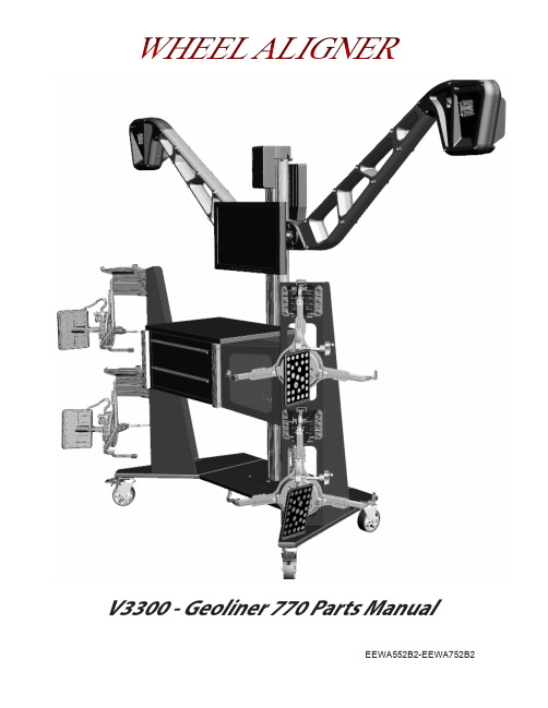
V3300 - Geoliner 770 Parts ManualEEWA552B2-EEWA752B2Table of ContentsALIGNMENT MODELS (2)BOM V3300 - GEOLINER 770 (3)KIOSK (4)ELECTRICAL SHELF (6)LEFT HAND CAMERA ARM (8)CAM-CAM (10)RIGHT HAND CAMERA ARM (12)CAM-TAR (14)TOWER (16)SLIDE CAR (18)AC400 WHEEL CLAMP (20)AC100 / AC200 WHEEL CLAMP (22)T E E W A 552B 23 - V 3300 - G E O L I N E R 770 S P A R E P A R T SPart numbers and descriptions are for reference purposes only. Not all parts shown are stocked as service parts, consult your partsdepot warehouse for availability.MODEL # DESCRIPTIONEEWA552B2 V3300 JOHN BEAN, AC400EEWA552H2 V3300 JOHN BEAN, AC200EEWA752B2 GEOLINER 770,HOFMANN,AC400EEWA752H2 GEOLINER 770,HOFMANN,AC200EEWA552BE2 V3300 JOHN BEAN, AC400 ETHOS EEWA552HE2 V3300 JOHN BEAN, AC200 ETHOSEEWA752BE2 GEOLINER 770,HOFMANN,AC400 ETHOS EEWA752HE2 GEOLINER 770,HOFMANN,AC200 ETHOS EEWA552BV2 V3300 JOHN BEAN, AC400 W/VIN SCANNER EEWA552HV2 V3300 JOHN BEAN, AC200 W/VIN SCANNEREEWA752BV2 GEOLINER 770,HOFMANN,AC400 W/VIN SCANNER EEWA752HV2GEOLINER 770,HOFMANN,AC200 W/VIN SCANNERALIGNMENT MODELS 2TEEWA552B23 - V3300 - GEOLINER 770 SPARE PARTSPart numbers and descriptions are for reference purposes only. Not all parts shown are stocked as service parts, consult your partsdepot warehouse for availability.BOM V3300 - GEOLINER 770PART NUMBER DESCRIPTIONEAK0289J86B KIT-VIN SCANNER (OPTION)3-08006A KIT – MOUSE/KEYBOARD, USB EAK0268J05A PRINTER KIT - USB EAW0290J26A POWER CORD-5 METERS EAL0343J76A LABEL - SERIAL96DEPRESSOR ASSY. PEDAL 55502STEERING WHEEL HOLDEREAK0289J61C KIT – MONITOR 24” W/ HDMI (MTG SCREWS IN KIT)1-39506A SCREW – PHM, M8 X 16MM (MTG CLAMP HOLDER TO KIOSK)EAC0129J41A CLAMP HOLDER, LOWER1-64209A SCREW – BHC, M12 X 25MM (MTG TOWER TO BASE)EAC0090J82A WHEEL CHOCK RUBBEREAL0392J89A LABEL - CUSTOMER SERVICE JBC EAK0320J26A KIT – AC400, FRONT SHIPMENT, PAIR EAK0305J60A KIT – AC400, REAR SHIPMENT, PAIR EAK0320J99A KIT - V3300 DECALS EAK0334J03A KIT – GEO 770XD DECALS TEEWA552B0INSTALLATION INSTRUCTIONS ZEEW A552B OPERATOR’S MANUAL EAA0469J60A ARM – RH ASM, CAM/TAR, FF EAA0469J61A ARM – LH ASM, CAM/CAM, FF EAA0469J33AKIOSK ASM – JBC EAA0469J66A KIOSK ASM – HOF EAA0469J50A COLUMN – V3300EAA0469J77A FULL ASM-V3300 ELECT. SHELF 3-82226A SOFTWARE LICENSE-MITCHELL1EAK0320J98B KIT, DOCKING1-05737A NUT-KEPS,M8 (ATTACH CLAMP HANGERS TO KIOSK)1-2541WASHER-FLAT,5/16” (ATTACH CLAMP HANGERS TO KIOSK)3T E E W A 552B 23 - V 3300 - G E O L I N E R 770 S P A R E P A R T SPart numbers and descriptions are for reference purposes only. Not all parts shown are stocked as service parts, consult your partsdepot warehouse for availability.KIOSKEAA0469J33A - JBCEAA0469J66A - HOFMANN4 71920 232526272832 824313436930111718212235363839112EAK0320J98B - KIT DOCKING PADS (OPTIONAL)• EAC0116J57B - PAD• 1-27184A - DRIVE ANCHOR, ¼”X1” LG• 4- EAC0129J41A - WHEEL CLAMP HOLDER LOWER • 1-39506A - SCREW – PHMS, M8 X 1.25MM X 16MM4TEEWA552B23 - V3300 - GEOLINER 770 SPARE PARTSPart numbers and descriptions are for reference purposes only. Not all parts shown are stocked as service parts, consult your partsdepot warehouse for availability.SYM REQ PART NO DESCRIPTION1 1 1-03382A CLAMP METAL, 1/22 2 1-04107A SCREW-PHM, M5X20MM, NYLOK3 6 1-05737A NUT - KEPS,M84 2 1-11103 M3 X 10MM FLAT HEAD SCREW5 2 1-11233 NUT - HEX, M3 DIN 9346 24 1-5433 NUT - KEPS, 5/16-187 2 1-14076A HOLE PLUG - 3/16" DIA, BLK 8 8 1-17358 RIVET, ALUMINUM 4MM 9 28 1-2541 WASHER, FLAT 5/1610 14 1-32601A MSCR,HEX HD, M8X20MM11 2 1-36109A2 SCR-SKT BTN HD CAP-BLK (M5 X 10MM) 12 1 1-42006A SCREW - #10-14 X 3/4, (SELF TAP) PHM 13 2 1-5665 BUSHING - SHOULDER14 8 1-65109A SCREW - BTN HD CAP,M4X8MM 15 2 8-04842A MAGNET, 12MM X 15MM X 3MM 16 2 8-06488A SLIDE-DRAWER17 1 8-10216A BUSHING - UNIVERSAL, 18 1 8-23762A LABEL - EARTH SYMBOL19 2 8-33939A CASTER - SWIVEL 5" W/ BRAKE 20 2 8-33939B CASTER - SWIVEL 5" W/O BRAKE 21 1 111243 LABEL-WARNING EXPLOSION 22 1 00111245000 LABEL CAUTION ELECTRICAL 23 1 EAA0429J86A KIOSK DOOR - JBC RED EAA0429J87A KIOSK DOOR - HOF BLUE 24 1 EAA0446J86A KIOSK BOX ASM - BLACK 25 1 EAA0469J27A LH TOWER ASM - JBC RED EAA0469J29A LH TOWER ASM - HOF BLUE 26 1 EAA0469J28A RH TOWER ASM - JBC RED EAA0469J30A RH TOWER ASM - HOF BLUE 27 1 EAA0469J34A RH KIOSK BRIDGE - JBC RED EAA0469J37A RH KIOSK BRIDGE - HOF BLUE 28 1 EAA0469J35A LH KIOSK BRIDGE - JBC RED EAA0469J36A LH KIOSK BRIDGE - HOF BLUE 29 1 EAA0469J71A PRINTER DRAWER ASM - V330030 1 EAA0469J78A BASE ASM - SF, TRUSS - V330031 4 EAC0116J56A CAP, CORNER TRIM 32 2 EAC0121V05A DOOR TRIM, FRONT33 2 EAC0121V09A INSERT, PRINTER DOOR 34 2 EAC0123J01A CORNER TRIM - KIOSK35 1 EAL0392J18A LABEL - PATENT ALIGNMENT 36 1 EAL0392J89A LABEL - CUSTOMER SERVICE 38 1 EAA0473J15A KIOSK GUSSET - LH,JBC RED EAA0473J17A KIOSK GUSSET - LH,HOF BLUE 39 1 EAA0473J16A KIOSK GUSSET - RH,JBC RED EAA0473J18A KIOSK GUSSET - RH,HOF BLUE5T E E W A 552B 23 - V 3300 - G E O L I N E R 770 S P A R E P A R T SPart numbers and descriptions are for reference purposes only. Not all parts shown are stocked as service parts, consult your partsdepot warehouse for availability.ELECTRICAL SHELFEAA0469J77A1356 81213151617202223272930313233353637382 479 101117 1819 2124 252628 346TEEWA552B23 - V3300 - GEOLINER 770 SPARE PARTSPart numbers and descriptions are for reference purposes only. Not all parts shown are stocked as service parts, consult your partsdepot warehouse for availability.SYM REQ PART NODESCRIPTION 1 2 1-01737A NUT - ESNA,M42 2 1-12224A SCREW - THREAD FORMING, M3X0.53 2 1-13633A NUT - BARB,EXT.WASHER,M54 2 1-15033 NUT - KEPS, M3 - .55 7 1-3347 LOCKWASHER, INTERNAL TOOTH6 2 1-38606A SCREW - PHM M3 X 6MM W LOCK WASHER7 3 2-10346B WIRE CONNECTOR-5WIRE,12-22 AWG8 1 2-14258A ROCKER SWITCH, ILLUMINATED, GREEN9 4 2-15651A FUSE HOLDER10 4 2-18451A FUSE - 5A SLOW BLOW11 1 2-64448A IEC 320-C14 AC RECEPTACLE 12 2 2-78266A RECPT, NEMA 5-15 TO IEC 13 1 2-78566ABASE - ANTENNA, MAGNETIC 14/15 1 EAK0350J78A KIT-V3300 USB 1 AC/DC ADAPTOR1USB HUB-6 PORT POWERED 16 1 8-09819A STRAIN RELIEF ROUND CABLE 17 2 8-23762A LABEL - EARTH SYMBOL18 1 86164 LABEL - WARNING, FUSE RATING 19 1 86465LABEL - WARNING, SHOCK HAZARD 20 1 00111245000 LABEL CAUTION ELECTRICAL 21 1EAA0416V65A IEC POWER BLOCK, 3 WAY22 1 EAK0350J68A HOST CONTROLLER, SVC V3300 23 1 EAA0469J76A ELECT. SHELF ASM - V330024 1 EAE0049J84A POWER SUPPLY - ALIGNER 25 1 EAE0078J06A POWER SUPPLY - ALIGNER 26 2 EAL0345P51A LABEL FUSE 5 A27 1 EAL0345P54A ELECTRICAL WARNING LABEL 28 1 EAS2105J96B COVER - OUTLET 29 1 EAS2186J77A BRACKET - USB30 4 EAW0290J16A CORD - POWER, V3300 POWER SHELF 31 1 EAW0290J17A CABLE ASM - ALIGNER POWER,32 2 EAW0290J18A LINK WIRE - 11 IN, BLK, 16 AWG 33 2 EAW0290J19A LINK WIRE - 11 IN, WHITE, 16 AWG 34 1 EAW0290J20A GRND WIRE - 6 IN, GR/YL, 16 AWG 35 2 EAW0290J22A CABLE ASM - DC BARREL (MALE)36 1 EAW0290J23A LINK WIRE - 6 IN, BROWN, 16 AWG 37 1 EAW0290J24A LINK WIRE - 6IN, BLUE, 16 AWG 38 22-31001A TERMINAL - QUICK CONNECT7T E E W A 552B 23 - V 3300 - G E O L I N E R 770 S P A R E P A R T SPart numbers and descriptions are for reference purposes only. Not all parts shown are stocked as service parts, consult your partsdepot warehouse for availability.LEFT HAND CAMERA ARM23456781091112131EAA0469J61A8TEEWA552B23 - V3300 - GEOLINER 770 SPARE PARTSPart numbers and descriptions are for reference purposes only. Not all parts shown are stocked as service parts, consult your partsdepot warehouse for availability.SYM REQ PART NO DESCRIPTION1 16 1-04937A NUT - M6, NYLON LOCK2 1 1-05037A NUT - M6, SQUARE3 6 1-16523 PHMS M2.9X9.5MM, SELF TAP4 2 1-21604A SCREW - M6 X 100MM, SHC5 15 1-21704A SCREW - M6 X 90MM SHC 6 6 5-07745A HOLDER - CABLE TIE7 6 5-845CABLE TIE8 1 EAA0469J59A CAM/CAM ASM FULL9 1 EAC0116J83A COVER - FT LH, CAMCAM10 1 EAC0116J85A COVER - LH BACK, CAMCAM FF 11 1 EAC0116J86A TRUSS ARM - PIVOT, FRONT FF 12 1 EAC0116J90A TRUSS ARM - PIVOT, REAR FF 13 1 EAL0452J32A DECAL - CAMERA, LH, FF14 1 EAW0290J10A CABLE ASM - MOTOR/CAMERA15 1 EAW0290J43A CABLE-ETHERNET CAT 6, 2 METERS9T E E W A 552B 23 - V 3300 - G E O L I N E R 770 S P A R E P A R T SPart numbers and descriptions are for reference purposes only. Not all parts shown are stocked as service parts, consult your partsdepot warehouse for availability.CAM-CAMEAA0469J59A - NA123 45 6789101112131410TEEWA552B23 - V3300 - GEOLINER 770 SPARE PARTSPart numbers and descriptions are for reference purposes only. Not all parts shown are stocked as service parts, consult your partsdepot warehouse for availability.SYM REQ PART NODESCRIPTION1 3 1-03907A SCREW - PHM, M3X4MM,NYLOK23 1-04737A NUT - LOCK, M33 1 1-1548 WASHER-EXT,SHAKEPROOF 6MM4 1 1-16209 SCREW HEX SOCKET HEAD CUP M6X125 1 1-18441A WASHER - #106 4 1-21404A SCREW - PHM, M2.5 X 8MM7 13 1-21904A SCREW - PHM, M2.5 X 6MM, LOCKING 8 4 1-29384A STANDOFF - M2.5 X 20MM9 3 1-30584ASTANDOFF - HEX, M3X5MM LG10 1EAK0334J29A FSK - CALIBRATED V3300 CAL CAM 11 1 EAK0350J66A KIT – CORTEX ASSEMBLY (WIRED)12 1 EAC0116J82A SKELETON - COMMON 13 1 EAC0129J39A BRACKET - CAMCAM, FF 14 1 EAP0280J74A STROBE 80 LEDS15 1 EAW0290J13A CABLE - MAIN TO CAL/COLORNS 1 EAW0290J43A CABLE-ETHERNET CAT 6, 2 METERS11T E E W A 552B 23 - V 3300 - G E O L I N E R 770 S P A R E P A R T SPart numbers and descriptions are for reference purposes only. Not all parts shown are stocked as service parts, consult your partsdepot warehouse for availability.RIGHT HAND CAMERA ARM2346810149111213155112345SYM REQ PART NO DESCRIPTION171-41006A SCREW - PHM, #8-16 X 1/2, TORX 21EAC0129J04A V3300 - ANTI REFLECTION, RH 31EAC0129J05A V3300 - ANTI, REFLECT, LH 41EAC0129J06A V3300 - ANTI, REFECT TOP 51EAC0129J07AV3300 - ANTI REFLECT, BOTTOMEAA0469J60A12TEEWA552B23 - V3300 - GEOLINER 770 SPARE PARTSPart numbers and descriptions are for reference purposes only. Not all parts shown are stocked as service parts, consult your partsdepot warehouse for availability.SYM REQD PART NO DESCRIPTION1 16 1-04937A NUT - M6, NYLON LOCK2 1 1-05037A NUT - M6, SQUARE3 12 1-16523 SCREW-PHMS, M2.9X 9.5MM,SELF TAP,TYPE B4 2 1-21604A SCREW - M6 X 100MM, SHC5 15 1-21704A SCREW - M6 X 90MM SHC 6 6 5-07745A HOLDER - CABLE TIE7 6 5-845TIE - CABLE8 1 EAA0420J54A CAMERA - COLOR AID9 1 EAA0446J52A V3300 - ANTI REFLECT ASM 10 1 EAA0469J58A TAR/CAM ASM-FULL11 1 EAC0116J86A TRUSS ARM - PIVOT, FRONT 12 1 EAC0116J87A COVER - FT RH, CAMTAR13 1 EAC0116J90A TRUSS ARM - PIVOT, REAR FF 14 1 EAC0123J02A BRACKET - DRIVE ON, CAMERA 15 1 EAC0123J13A COVER - RH BACK, CAMTAR FF 16 1 EAL0452J33A DECAL-CAMERA, RH FF17 1 EAW0290J10A CABLE ASM - MOTOR/CAMERA18 1 EAW0290J43A CABLE-ETHERNET CAT 6, 2 METERS13T E E W A 552B 23 - V 3300 - G E O L I N E R 770 S P A R E P A R T SPart numbers and descriptions are for reference purposes only. Not all parts shown are stocked as service parts, consult your partsdepot warehouse for availability.EAA0469J58A - NACAM-TAR1234567910111214TEEWA552B23 - V3300 - GEOLINER 770 SPARE PARTSPart numbers and descriptions are for reference purposes only. Not all parts shown are stocked as service parts, consult your partsdepot warehouse for availability.SYM REQ PART NO DESCRIPTION1 3 1-03907A SCREW-PHM, M3X4MM,NYLOK23 1-04737A NUT - LOCK, M33 1 1-1548 WASHER - M6, LOCK, EXT4 1 1-16209 SCREW - SHC, M6 X 16MM5 1 1-18441A WASHER - #106 9 1-21904A SCREW - PHM, M2.5 X 6MM, LOCKING7 3 1-30584A STANDOFF - HEX, M3X5MM LG8 1 EAA0381J26A TARGET SANDWICH, 6X8, “X”9 1 EAK0350J66A KIT – CORTEX ASSEMBLY (WIRED) 1 EAC0116J82A SKELETON - COMMON11 1 EAK0334J24B FSK-CAM/TAR BRACKET W/6X8 TARGET 12 1 EAP0280J74A STROBE 80 LEDS13 1 EAW0290J13A CABLE - MAIN TO CAL/COLORNS 1 EAW0290J43A CABLE - ETHERNET CAT 6, 2 METERS15depot warehouse for availability.203830353721 739723 29323336313152434241(EAK0334J70A - RUBBER WASHER)TEEWA552B23 - V3300 - GEOLINER 770 SPARE PARTSPart numbers and descriptions are for reference purposes only. Not all parts shown are stocked as service parts, consult your partsdepot warehouse for availability.SYM REQ PART NO DESCRIPTION 1 4 1-01537A NUT - LOCK, M3 2 1 1-09163A BEARING - NEEDLE, THRUST 3 1 SEE ITEM 34 BUSHING - OILITE, 1/2”, FLANGE 4 5 2 1-11308A WELD NUT - TAB, LOW PROFILE,#6-326 4 1-13204A2 SCREW - PHM, M4 X 10MM X 12MM 7 8 1-1337 NUT - ESNA, 5/16 -18 8 4 1-13641 WASHER - FLAT (12MM), BLK 9 8 1-15144A WASHER - CUSHIONING, #1010 2 1-16341A WASHER - FLAT (3MM), 9MM OD 11 4 1-16523 SCREW - PHMS,M2.9X 9.5MM,SELF TAP,TYPE B 12 2 1-16726A SCREW - THREAD CUTTING, (PLASTIC),#4-24 X 3/8”13 1 SEE ITEM 34 RETAIN RING - 1/2 DIA. BEARING 14 3 1-23223A SCREW - PHMS,M2.9 X 1 X 13MM,TYPE B 15 2 SEE ITEM 34 WASHER - THRUST 1/2”16 4 1-37306A SCREW - PHM, M3 X 16MM 17 8 1-48701A SCREW - HHW, #10-24 X 5/8,18 4 1-49410A SCREW - SET, FLAT PT 1/4-20 X 1/419 4 1-64009A SCREW, SHCS 10-24 X 220 4 1-64209A SCR - BTN HD SOCKET, M12 X 25MM 21 8 1-705A BOLT - CARRIAGE 5/16-18 X 3/422 4 1-7733 LOCK NUT - 10-24 X .375 23 1 EAK0334J21A FSK - 3300 MOTOR / MOTOR PLATE• 1 MOTOR • 2 MOTOR MOUNT - V3300• 4 SCREW - SHCS #10-24 X 2”• 4 LOCKNUT - #10-24 X 0.375”• 8 WASHER - CUSHIONING, #10 (EAK0334J70A SET OF 8)• 2 RUBBER FOOT • 2 NUT - LOCKING,M3• 2 SCREW - PHM,M3 X 16MM • 2 COUPLING-HUB,1/2” SHAFT (ITEM 32)• 1 CUSHION - COUPLING (ITEM 33)• 4 SCREW - SET,FLAT PT 1/4”-20 X 1/4”24 1 SEE ITEM 34 TUBING - PVC 25 4 8-08018A RUBBER FOOT 26 1 EAA0429J03A SLIDE CAR ALIGNER 27 1 EAA0429J05A TRACK - POWER 28 1 EAC0116J60A EXTRUSION, COLUMN 29 1 EAC0116J68A MOTOR COVER 30 1 EAC0116J98A MCB MOUNT 31 1 EAC0116J99A MCB BACK COVER 32 2 EAK0334J20A FSK - V3300 MOTOR COUPLING (COUPLING - HUB, 1/2” SHAFT)33 1 EAK0334J20A FSK - V3300 MOTOR COUPLING (CUSHION - COUPLING)34 1 EAK0334J19A FSK V3300 LEAD SCREW• 1 LEAD SCREW • 1 BUSHING - OILITE,1/2”,FLANGE • 1 RETAINING RING-1/2” DIA. BEARING • 2 WASHER - THRUST 1/2”• 1 TUBING-PVC • 2 COUPLING - HUB,1/2” SHAFT • 1 CUSHION - COUPLING • 1 NUT - LEAD SCREW • 1 8-03629A LUBRICANT-SUPER LUBE,3OZ TUBE35 1 EAP0280J90A MOTOR CONTROL BOARD NS 1 EAW0290J38A CABLE ASM-MOTOR,MCB 36 1 EAS2146J88A PLATE - TOP 37 1 EAS2186J30A BRACKET-MONITOR,SPLIT 38 1 EAS2171J52A ALIGNER/BASE MOUNTING PLATE 40 1 EAS2171J66A PLATE - CABLE TRACK 41 1 SEE ITEM 34 NUT - LEAD SCREW NS 1 EAW0290J41A CABLE - ETHERNET CAT 6, 12FT.17T E E W A 552B 23 - V 3300 - G E O L I N E R 770 S P A R E P A R T SPart numbers and descriptions are for reference purposes only. Not all parts shown are stocked as service parts, consult your partsdepot warehouse for availability.123 78 111213 141545610161718EAA0429J03ASLIDE CAR18TEEWA552B23 - V3300 - GEOLINER 770 SPARE PARTSPart numbers and descriptions are for reference purposes only. Not all parts shown are stocked as service parts, consult your partsdepot warehouse for availability.SYM REQ PART NO DESCRIPTION 1 2 SEE ITEM 14 SPRING - CONICAL 2 4 SEE ITEM 14 FHCS - M8 X 1.25, 20MM 3 16 SEE ITEM 8 MSCR - PH PAN HD,M3X8MM W/LK WASHER 4 4 1-07424A SCREW - PHH SLFTG-BLK(8-18X1/2) 5 1 1-32806A SCREW - PHMS #10-24 X 3/86 1 EAS2171J59A KEEPER - LEAD SCREW 7 8 SEE ITEM 8 BRACKET - ROLLER, V3300 8 1 EAK0334J22A FSK-V3300 SLIDE CAR ROLLERS• 8 BRACKET-ROLLER,V3300• 8 ROLLER• 12 SCREW-PHM,M3X8,LK WASHER • 8 SHAFT-ROLLER10 1 EAA0429J96A NUT & LEAD SCREW 11 1 EAC0116J96A SLIDE CAR - V3300 12 1 EAC0116J97A ARM - LEAD SCREW 13 8 SEE ITEM 8 SHAFT - ROLLER 14 1 EAK0334J23A FSK-V3300 LOCKING PINS• 4 FHCS - M8 X 1.25, 20MM • 2 SPRING - CONICAL • 2 DISC - ARM PIVOT • 2 LOCKING PIN ASM • 2 SHAFT - PIVOT• 1 SYNTHEIC GREASE15 2 SEE ITEM 14 DISC - ARM PIVOT 16 4 1-64709A SCREW-SKT HD LOW PROFILE,17 2 SEE ITEM 14 LOCKING PIN ASM 18 1 EAC0123J10A SKELETON - REINFORCING19T E E W A 552B 23 - V 3300 - G E O L I N E R 770 S P A R E P A R T SPart numbers and descriptions are for reference purposes only. Not all parts shown are stocked as service parts, consult your partsdepot warehouse for availability.PART NUMBER DESCRIPTIONEAK0305J65A XD TARGET ASM, REARPART NUMBER DESCRIPTIONEAA0395J13B XD TARGET ASM, FRONT EAM0088J15A* BUSHING - AC400, SP123 567910812119BEAA0381J05A DUAL WHEEL ADAPTERAC400 WHEEL CLAMPEAA0361J99ATEEWA552B23 - V3300 - GEOLINER 770 SPARE PARTSPart numbers and descriptions are for reference purposes only. Not all parts shown are stocked as service parts, consult your partsdepot warehouse for availability.ACCESSORIES EAK0305J50A KIT DUAL WHEEL ADAPTER (6)EAA0381J05A DUAL WHEEL ADAPTER (1)EAK0222J83BWHEELS OFF ADAPTER KITSYM REQD PART NO DESCRIPTION 1 1 1-20733A NUT - JAM, M82 2 1-62609ASCREW - SHC, #6-32 X 1/23 1 EAA0361J99A DNH - LEFT CLAMP ASM.DNH - RIGHT CLAMP ASM.4 1 EAA0381J34A XD TARGET ASM - FRONT5 1 EAL0415J09A DECAL - LEFT FRONT, INDICATOR EAL0415J10A DECAL LEFT REAR EAL0415J11A DECAL RIGHT REAR EAL0415J12A DECAL RIGHT FRONT6 1 EAM0007J19A SCREW - SHC, M8 SPECIAL7 1 EAM0088J15A BUSHING - AC400, SP8 EAA0381J12A KIT - KNOB SERVICE9 EAA0381J13A BRACKET PAW - SVC KIT 9B 1-25752AQUICK RELEASE BUTTON 10 EAC0105J78A HANDLE11 EAC0105J93A AC400 BUMPER TIGER PAW (RUBBER TIP ONLY)12 EAK0320J22A PLASTIC WASHER REPAIR KIT (TSB WA-1185-1)OPTIONAL CLAMP/TARGET KITS CLAMP VALID FOR V3300AC100EAK0320J36A AC200EAK0320J34A AC400EAK0320J35ANOTE: Each kit below contains (4) clamps & (4) targets for a complete alignerNOTE: There are NO Service items other than what is listed in this parts reference. At notime should a wheel clamp be disassembled in the field for repair.21T E E W A 552B 23 - V 3300 - G E O L I N E R 770 S P A R E P A R T SPart numbers and descriptions are for reference purposes only. Not all parts shown are stocked as service parts, consult your partsdepot warehouse for availability.AC100 / AC200 WHEEL CLAMPEAK0268J56A - WHEEL CLAMP LONG (NA) AC200EAK0268J78A - WHEEL CLAMP SHORT (EURO) AC100123456789101112131415161718192021222324 2522TEEWA552B23 - V3300 - GEOLINER 770 SPARE PARTSPart numbers and descriptions are for reference purposes only. Not all parts shown are stocked as service parts, consult your partsdepot warehouse for availability.SYM REQ PART NO DESCRIPTION 111-1041WASHER - FLAT, 1/2231-14144A WASHER-FLAT, M6381-17677A RETAINING RING 411-20733A NUT - JAM, M8541-28103A MSCR, PH FLH M4 X 25MM611-3447M6 LOCKWASHER, INTERNAL TOOTH 711-37410SCREW - SET M3 X .5 X 10MM, CUP PT.831-50309A SCREW - BHCS M6X10MM911-6152PIN-STRAIGHT SLOTTED M4 X 20MM 1011-933NUT - HEX, 1/2-13112EAC0079J48A BRACKET - LONG WHEEL CLAMP (FRONT)122EAC0079J50A COVER - FEED SCREW LOCK 132EAC0079J51A PLUG - PLASTIC, 19MM HOLE142EAC0079J52A WASHER - THRUST PLASTIC PLASTIC, 19MM HOLE 151EAC0079J53A CENTER SLIDE BRACKET 161EAM0044J13A KNOB HAND WHEEL172EAM0044J14A TUBE - WHEEL CLAMP LONG (NA)EAM0044J64A TUBE - WHEEL CLAMP SHORT (EURO)181EAM0044J16A SCREW - DOUBLE LEAD LONG (NA)1EAM0044J65A SCREW - DOUBLE LEAD SHORT (EURO)194EAM0044J19C GRABBER ASM SINGLE END 4EAM0044J19A GRABBER ASM DUAL END 201EAM0044J20A BUSHING - THREADED BRASS RH 211EAM0044J21A CENTER STATIONARY 222EAM0044J22A PIN - TUBE LOCK231EAM0044J24A BUSHING THREADED BRASS LH EAM0044J20A BUSHING THREADED BRASS RH 241EAM0044J47A SCREW - SHCS M8X30 FULL THD 252EAS2084J29APLATE - RETAINERPART NUMBER DESCRIPTION1-08584ACORD – BUNGEE, BLACK 16”EAK0268J41D GRABBER KIT, SINGLE END EAK0268J41B GRABBER KIT – DUAL END EAC0105J35A COVER-RUBBER, V3DWHEEL CLAMP EXTENSIONEAK0268J62A23T E E W A 552B 23 - V 3300 - G E O L I N E R 770 S P A R E P A R T SPart numbers and descriptions are for reference purposes only. Not all parts shown are stocked as service parts, consult your partsdepot warehouse for availability.BLANK PAGE24TEEWA552B23 - V3300 - GEOLINER 770 SPARE PARTSPart numbers and descriptions are for reference purposes only. Not all parts shown are stocked as service parts, consult your partsdepot warehouse for availability.BLANK PAGE25Snap-on309 Exchange Ave.Conway, AR 72032501-450-1500TEEWA552B23_RevD 04/2020...rjh Printed in the U.S.A。
MT产品培训手册--梅特勒-托利多

钢管秤结构:1260传感器
较大台面,抗冲击
槽钢秤结构:IL钢质传感器
大台面,高强度耐冲击
1.3
1.3.1
高端:VIPER秤
VIPER SG
VIPER MonoBloc
VIPER高精度计数秤
中端:T-Count加外接秤台
低端:TC计数秤;TCII计数秤
TC计数秤规格:
机械加工、粮食、酿酒厂
1.1.4
1.1.4.1基本型1:PK系列平台秤
带框架,可配引坡
自复位传力机构:限位不会卡死
烘漆:丙稀酸聚氨脂漆
台面低,外观美观
称量准确
安装方式灵活
准确度:III级
量程:1~10t
规格:1X1~2X4m
1.1.4.2基本型2:PW系列无框架平台秤
无框架,不能配引坡
全花纹板台面
搬动方便/易于维护和清理
CranemateE仪表:打印功能
1.4.4.4行业专用秤:防磁防热吊秤
行业:冶金/铸造/有色冶炼,高温,防磁
防热:高温传感器/高温电池/双层钢结构/隔热板/辐射板
防磁:全钢结构/不锈钢仪表壳/高功率发射
称钢/铁水包:质量控制/省能源/时间
冶炼配比/加球化剂:科学准确/质量/效率
流程:进/工艺/出,利润管理/控制成本/贸易结算
中高精度:4000~6000
框架上带4只支脚
台面上装水平指示器
秤台加厚:刚度/强度高
高精度不锈钢传感器:0.01%
仪表显示分度数高达:50000
1.1.4.5移动式:PT/PTS系列移动式平台秤、叉车秤
1.1.4.5.1PT系列
移动方便
Met One 905 三脚架产品说明书

MODEL 905TRIPODOPERATION MANUALMet One Instruments, IncCorporate Sales & Service: 1600 NW Washington Blvd. Grants Pass, OR 97526 Tel (541) 471-7111 Fax (541) 471-7116 - ******************Technical SupportShould you require support, please consult your printed documentation or our website to resolve your problem. If you are still experiencing difficulty, you may contact a Technical Service representative during normal business hours;Monday – Friday 7:00 a.m. to 4:00 p.m. Pacific Time.Voice: (541) 471-7111Fax: (541) 471-7116E-Mail: ******************Mail: Technical Services DepartmentMet One Instruments, Inc.1600 NW Washington BlvdGrants Pass, OR 97526Table of ContentsSpecification: (3)Transport Mode (3)Erecting (3)Figure 1 Erecting (4)Raising and Lowering (4)Guying (5)Securing the Tripod to the Ground (6)Figure 3 Securing to the ground (6)Tripod Mounting Base Detail (7)Replacement parts (8)MODEL 905 TRIPODOPERATION MANUALThe Model 905 is a lightweight collapsible tripod designed for rapid deployment and retrieval. It can be easily transported and erected by a single person. It is intended to support a complement of weather or atmospheric instrumentation weighting up to 15 pounds at winds up to 90 mph.Specification:Weight 15 poundsCollapsed length 48 inchesErected height 6 feet or telescoping to 10 feet. Unit is providedwith guy cables when mast is erected to 10 feetheight.Instrument mounting Top of mast is same diameter as ¾ inch waterpipe, to fit most cross arm clasps. All othermembers are 1-5/16 inch diameter.Materials Stainless steel or epoxy painted aluminum. Transport ModeWhen collapsed, the tripod legs are folded upward. The stainless steel release pins are replaced in their holes to prevent loss. The mast is telescoped inward and retained by the long stainless steel release pin. In this mode the overall length is 48 inches and the overall diameter is 9 inches. The guy cables are normally removed in this mode to make handling easier. Place them in the plastic bags provided to avoid tangling and damage.ErectingSee Figure 1. This is usually easier if the tripod is placed upside down. Remove one of the stainless steel pins and pivot the leg until the tongue bottoms between the two plates on the hub; then reinsert the release pin. Repeat for the remaining two legs. Turn the tripod right side up and stand it on its legs.Figure 1 ErectingRaising and LoweringAt the 6-foot height, the mast release pin will always remain in place to ensure North orientation. If the 10-foot height is being used, note that the telescoping section has two aligned holes, one at the top and one further down. Any alignment made with the mast at six feet will be maintained when the mast is elevated to 10 feet if these holes are used. To raise the mast, simply remove the pin, slide the mast up until the upper set of holes align and re-pin.GuyingAt the 6-foot height, guy cables are not required. At 10 feet the guy cables should be used. To install the guy cables, simply slip the ball end of the cable into one of the holes at the top of the mast, bring the cable down through the slot at the bottom of the hole. See Figure 2. Open the latch at the bottom of the cable and insert the hook into the slit at the bottom of the appropriate leg. Repeat for all three legs. Do not close the latches at the lower ends of the cables until all three cables are attached. To lower the mast, it is necessary to first release all three latches. The guy cables are spring loaded and should never require adjustment. Figure 2 GuyingSecuring the Tripod to the GroundThe unit will free stand in no-wind conditions. In wind up to 30 mph, thecenter tether may be used. See Figure 3.Figure 3 Securing to the groundThe auger is intended for use in firm soil. If the terrain is soft (i.e. sand or snow) the tether can be attached to a buried plate. The tether is supplied with an eyebolt, which may be fastened to a piece of plywood, sheet metal, or other convenient material, then buried. If the legs sink into soft terrain, likewise attach a piece of wide flat material to each leg with a bolt through each foot. Foot pads do not get buried.The unit can also be staked to firm soil with steel re-bar stakes at each foot.In winds over 30 mph the unit should be bolted or lag screwed to a solid deck. Holes are provided in the feet for this purpose.If properly secured to a solid deck and with the guy wires in place, the unit will withstand 90 mph winds.Tripod Mounting Base DetailFig. 4 Mounting Base Detail of 905 TripodNote: The radius dimension does have some tolerance to it as the legs on the tripod can shift out or in about 3/16 of an inch while in installation.Replacement partsThe following replacement parts may be ordered from Met One Instruments.1.Guy wire kit, MOI#100372.Short stainless steel release pin. ¼” X 1” (For legs, 3 required), MOI#7902323.Long stainless steel release pin. ¼” X 1 ½” (For telescoping mast), MOI#7902334.Ground tether kit, including: latch, spring, chain, eyebolt and auger. MOI#7090-15.Replacement guy wires. 1/16” X 105” S.S. ,MOI#9750026.Mast Guide (top guide) attached to the fixed (outer) mast housing. MOI#31777.Mast Sleeve (bottom guide) attached to the sliding (inner) mast. MOI#3176。
avimb-005_V03监视和测量装置控制程序
监视和测量装置控制程序编号:avim/B-0051目的有效的控制计量工具、检测仪器及试验装置的添置、领用、校验和报废。
2适用范围公司使用的所有计量器具、检测仪器及试验装置的添置、领用、校验和报废。
3职责3.1设备部负责各类仪器、装置、量具的统计、检定周期的制定和定期送检。
3.2使用部门负责对所使用的仪器的保养。
4术语与定义外校:指本公司内部无法校验而送到其他有能力和资格的单位进行定期校验。
5程序5.1计量工具、检测仪器及试验装置进行编号设备部负责对本公司所有计量工具、检测仪器及试验装置进行统一编号。
5.2计量工具、检测仪器及试验装置的添置和领用。
5.2.1添置计量工具、检测仪器及试验装置时,须填写申请单,经部门领导审核,总经理批准后由采购部购买。
5.2.2采购人员根据申请单的要求购买计量工具、检测仪器及试验装置。
5.2.3计量工具、检测仪器及试验装置购回后,应将计量工具、检测仪器及试验装置资料(包括名称、型号、规格、说明书等)交设备部,另新购回的仪器其合格证若能追溯到相关的国家或国际标准,可判定其合格,日期以购回日期开始,一年为限。
5.2.4设备部负责检查购回的计量工具、检测仪器及试验装置,对合格品进行编号,做标记后登录在“计量器具台帐”上,不合格则按《不合格品控制程序》执行。
5.3计量工具、检测仪器及试验装置校验5.3.1设备部负责对公司所有计量工具、检测仪器及试验装置制定校验周期,记录在“计量器具台帐”上。
5.3.2设备部按照“计量器具台帐”对计量工具、检测仪器及试验装置按期送到相关检测机构校验,做好校验后,须在相应的仪器、装置贴上状态标签等。
5.3.3使用仪器时,若发现超过有效期或使用人怀疑仪器不准确时,应主动送到设备部,由设备部送相关的检测机构校验。
5.3.4超过校验有效期和计量时发现不准的计量工具、检测仪器及试验装置,设备部负责追溯此仪器检测的产品,并由设备部决定对这些产品的处理方式。
VICTOR05回路校验仪说明书

+
电源
5--25VDC电源
注意 ·供电电源范围:5~25VDC ·使用:在输出电流时,应尽可能采用外部的 24VDC 电源,使用变送器接线方式,这样可很大 的延长电池寿命
VC05 Page 4 of 11
6. 仪表的测量
▲警告·使用:所有端子间及端子到地所允许的最大电压为 30V,超过此电压不仅造成对仪表的 损坏而且也可能对人员造成伤害
·清理:定期用湿布和清洁剂清理仪表的外壳,切勿使用腐蚀性溶剂
注意
·使用:为保证使用精度,开机后应预热 5 分钟
·使用:用户若对本仪表有更高的精度要求时,请与生产厂家或经销商联系
2. 仪表面板组成和功能
LCD 显示区
05 LOOP CALIBRATOR
电源开关键 单步/自动切换键 25% 单 步 设 定 / 自 动 斜波切换键
不要短路或施加超过最大允许值的电压到本仪表输出端和标准器否则它们的内部电路可能被损坏91选择标准设备选择标准设备输出特性校准输出特性校准校准项目校准项目标准设备标准设备输输入入量量程程精精度度推推荐荐dca20ma数字表max22ma50ppm04ua1281fluke或相等vc05page9of11输入特性校准输入特性校准校准项目校准项目标准设备输出量程输出量程精精度度推推荐荐标准设备dca20ma标准源max33ma100ppm02uadcv28v标准源max33v12ppm15uv5520fluke或相等5520fluke或相等92校准的环境条件校准的环境条件环境温度
VC05 校准器使用说明书
回路校准器(LOOP CALIBRATOR)
1. 安全使用
VC05 校准器(CA0E)使用说明书(E100005) FA2—E100005 / VER.(0.0)/ NUM.(1/1)
METTLER TOLEDO 天地力衡系统模块权重系统手册说明书
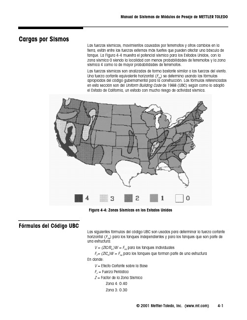
© 2001 Mettler-Toledo, Inc. ()4-1Cargas por SismosLas fuerzas sísmicas, movimientos causados por terremotos y otros cambios en la tierra, están entre las fuerzas externas más fuertes que pueden afectar una báscula de tanque. La Figura 4-4 muestra el potencial sísmico para los Estados Unidos, con la zona sísmica 0 siendo la localidad con menos probabilidades de terremotos y la zona sísmica 4 como la de mayor probabilidades de terremotos.Las fuerzas sísmicas son analizadas de forma bastante similar a las fuerzas del viento.Una fuerza cortante equivalente horizontal (F EQ ) se determina usando las fórmulasapropiadas del código gubernamental para la construcción. Las fórmulas referenciadas en esta sección son del Uniform Building Code de 1988 (UBC) según como lo adoptóel Estado de California, un estado con mucho riesgo de actividad sísmica.Figura 4-4: Zonas Sísmicas en los Estados UnidosFórmulas del Código UBCLas siguientes fórmulas del código UBC son usadas para determinar la fuerza cortante horizontal (F EQ ) para los tanques independientes y para los tanques que son parte de una estructura:V = (ZIC/R w )W = F EQ para los tanques individualesF P = (ZIC P )W = F EQ para los tanques que forman parte de una estructura En donde:V = Efecto Cortante sobre la Base F P = Fuerza PeriódicaZ = Factor de la Zona SísmicaZona 4: 0.40Zona 3: 0.30Zona 2B: 0.20Zona 2A: 0.15Zona 1: 0.10I = Factor de ImportanciaMateriales no peligrosos: 1.00Materiales peligrosos: 1.25 a 1.50C = Coeficiente de Fuerza Lateral: 2.75 para la mayoría de las condicionesCP= Coeficiente de Fuerza Lateral (Tanque como parte de una estructura)Materiales no peligrosos: 0.75Materiales peligrosos: 1.25Recipientes en el techo del edificio: 2.00RW= Coeficiente Numérico de las Tablas 23-O y 23-Q de UBCRecipientes y Tolvas: 4.00Tanques: 3.00Factores FEQBasados en elCódigo UBCLa Tabla 4-1 ofrece un método más sencillo para determinar la fuerza cortantehorizontal (FEQ ). Los factores listados en la tabla están basados en las fórmulas delCódigo UBC presentadas arriba.Sin Peligro PeligrososConservador No Conservador Recipiente o Tolva IndependientesZona 40.280.410.34Zona 30.210.310.26Zona 2B0.140.210.17Zona 2A0.100.150.13Zona 10.070.100.09 Tanque IndependienteZona 40.370.550.46Zona 30.280.410.34Zona 2B0.180.280.23Zona 2A0.140.210.17Zona 10.090.140.11 Recipiente, Tolva o Tanque EstructuralZona 40.300.750.63Zona 30.230.560.47Zona 2B0.150.380.31Zona 2A0.110.280.23Zona 10.080.190.16 Recipiente, Tolva o Tanque Montado en el TechoZona 40.80 1.20 1.00Zona 30.600.900.75Zona 2B0.400.600.50Zona 2A0.300.450.38Zona 10.200.300.25 Tabla 4-1: Factores de Fuerzas Cortantes Horizontales (FEQ) Basados en el Código UBC© 2001 Mettler-Toledo, Inc. ()4-2Encuentre su aplicación en la tabla, basado en la localización del tanque, su contenido y la zona de fuerzas sísmicas. Multiplique el factor correspondiente por el peso bruto del tanque o del recipiente. El valor resultante será igual a la fuerza cortante horizontal(FEQ) aplicada al centro de gravedad del tanque (ver la Figura 4-5).Figura 4-5: Fuerza Cortante Horizontal Aplicada al TanqueLas fuerzas de reacción en los módulos de peso son determinadas usando la Estática(ver Apéndice 4) basada en la fuerza cortante (FEQ ) aplicada al centro de gravedad deltanque. Compare las fuerzas de reacción con las cargas permitidas para los módulos de peso (ver Apéndice 5). Los módulos de peso pueden entonces dimensionarse para acomodar las cargas sísmicas resultantes, o se pueden añadir puntos de verificación externos según sea necesario para contrarrestar las cargas sísmicas.© 2001 Mettler-Toledo, Inc. ()4-3。
发动机台架标定培训教材

八.爆震窗口的标定
发动机爆震一般发生在上止点后0—30度,设 定爆震窗口的起始时间和窗口的长度,使爆 震窗口完全覆盖发动机发生爆震的范围,便 于ECU准确控制爆震的发生.
爆震窗口起始时间的标定
标定起始时间时 结合示波器的波 形图使窗口的起 点尽量接近爆震 波的起点
爆震窗口长度的标定
以窗口覆盖整个 爆震波为宜.
九.COT〔催化器过热保护
一.COT<催化器过热保护>条件: ⑴设定较高的温度不让发动机进入催化器过热
保护<一般温度设为1024度 kfcotp_convtemp max limit<fixed curve> kfcotp_convtemp control limit<fixed curve> kfcotp_convtemp control limit hyst kfcotp_convtemp timer reset limit <fixed curve
谢 谢!
让我们共同进步
PE动力加浓标定
爆震窗口标定
COT催化器过热保护
发动机外特性试验<WOT>及万有特性试验
二.台架准备工作
1.安装进排气系统测量温度和压力的传感器 2.在排气管上安装测量空燃比的λ-CAN 3.从爆震传感器引线连到示波器测量爆震〔安装
燃烧分析仪测量爆震 4. 检查发动机零部件是否按照要求提供及安装,各
零部件均能正常工作,发动机各缸缸压及均匀性是 否良好,发动机压缩比是否满足开发要求等,记录零 部件编号
二.台架准备工作
5.发动机基本性能测试 5.1 发动机状态检查 将发动机运行于以下工况,保证其性能良好.在点火
角与空燃比标定前可通过Slew<回摆>功能测试.此 工作每天台架试验前须完成,以确认发动机状态是 否良好. 发动机外特性扭矩、功率与油耗率; 最大扭矩点角的标定
优宝常用仪表标定大全
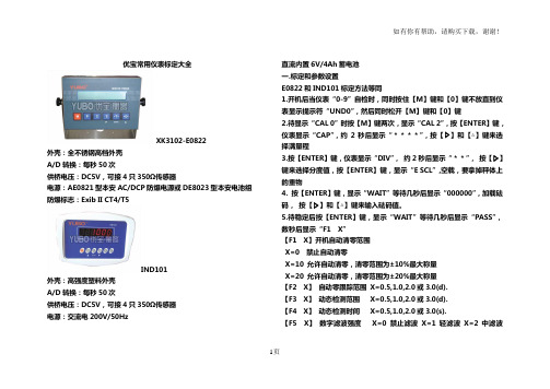
1页优宝常用仪表标定大全XK3102-E0822外壳:全不锈钢高档外壳 A/D 转换:每秒50次供桥电压:DC5V ,可接4只350Ω传感器电源:AE0821型本安AC/DCP 防爆电源或DE8023型本安电池组 防爆标志:Exib II CT4/T5IND101外壳:高强度塑料外壳 A/D 转换:每秒50次供桥电压:DC5V ,可接4只350Ω传感器 电源:交流电200V/50Hz直流内置6V/4Ah 蓄电池 一.标定和参数设置E0822和IND101标定方法等同1.开机后当仪表“0-9”自检时,同时按住【M 】键和【0】键不放直到仪表显示提示符“UND0”,然后同时松开【M 】键和【0】键2.待显示“CAL 0”时按【M 】键两次,显示“CAL 2”,按【ENTER 】键,仪表显示“CAP ”,约2秒后显示“****”,按【▷】和【△】键来选择满量程3.按【ENTER 】键,仪表显示“DIV ”, 约2秒后显示“**”, 按【▷】键来选择分度值,按【ENTER 】键,显示“E SCL ”,空载,要拿掉秤体上的重物4. 按【ENTER 】键,显示“WAIT ”等待几秒后显示“000000”,加载砝码, 按【▷】和【△】键来输入砝码值。
5.待稳定后按【ENTER 】键,显示“WAIT ”等待几秒后显示“PASS ”,数秒后显示“F1 X ”【F1 X 】开机自动清零范围 X=0 禁止自动清零X=10 允许自动清零,清零范围为±10%最大称量 X=20 允许自动清零,清零范围为±20%最大称量 【F2 X 】 自动零跟踪范围 X=0.5,1.0,2.0或3.0(d). 【F3 X 】 动态检测范围 X=0.5,1.0,2.0或3.0(d). 【F4 X 】 动态检测时间 X=0.5,1.0,2.0或3.0(s).【F5 X 】 数字滤波强度 X=0禁止滤波 X=1轻滤波 X=2中滤波 X=3强滤波【F8 X】扩展显示方式【F9 X】设置工厂缺省值二.错误提示1.OVER 表示:重量数据超载或欠载。
MT70 立体力学实验设备操作手册说明书

1KGS Flh Bedienungsanleitung3B SCIENTIFIC ® PHYSICSU15033 Standfestigkeitsapparat6/03 ALF®Der Standfestigkeitsapparat dient zur Demonstration der Standfestigkeit eines Objekts in Abhängigkeit der Schwerpunktlage über der Standfläche.1. Beschreibung, technische DatenDer Standfestigkeitsapparat besteht aus 3 in gleichen Abständen übereinanderliegenden Metallplatten, die mit 4 M etallstangen durch Gelenke verbunden sind. Im Schwerpunkt des Gerätes, in der Mitte der mittleren Plat-te, ist ein Senklot aufgehängt.Abmessungen: 180 mm x 150 mm x 290 mm2. PrinzipEine stabile Gleichgewichtslage eines stehenden Körpers ist nur dann gegeben, wenn das Lot auf den Mittelpunkt der Standfläche trifft. Die Standfläche hebt dann die Wir-kung der am Schwerpunkt angreifenden Schwerkraft auf.Geht das Lot nicht durch diesen Punkt, greift ein von der Schwerkraft hervorgerufenes Drehmoment am Schwer-punkt des Körpers an und bringt ihn zum Kippen.Im Schwerpunkt S greifen zwei Kräfte an, die Gewichts-kraft G und horizontal die Kraft F, die versucht den Kör-per um die Kante K zu kippen. Sie verursacht ein Dreh-moment M kipp = Fh mit K als Drehachse. Diesem Dreh-moment wirkt das von der Gewichtskraft hervorgerufe-ne Drehmoment M gew = Gl entgegen. Solange Fh = Gl ist,bleibt der Körper im Gleichgewicht und kippt nicht. Die Kraft F = Gh/l dient als Maß der Standfestigkeit eines mit einer Fläche aufliegenden Körpers. Je größer das Gewicht G und der Abstand l des Auftreffpunktes des Lots von der Kante K und je kleiner die Höhe h des Schwerpunkts über der Auflagefläche ist, desto größer ist die Standfestigkeit des Körpers.3. Bedienung•Den Standfestigkeitsapparat auf eine horizontale Un-terlage stellen.•Dem Gerät verschiedene Neigungen erteilen.•Gleichgewicht ist stabil, wenn der Schwerpunkt über der Auflagebasis liegt.•Gleichgewicht ist labil, wenn der Schwerpunkt über der Kippungskante liegt. (Ein kleiner Stoß reicht zum Umkippen aus.)•Wenn der Schwerpunkt nicht mehr über der Auflage-basis oder über der Kippungskante liegt, kippt der Standfestigkeitsapparat von selbst um.•Schwerpunktlage ist durch das Lot immer erkennbar.•Kraft, die zum Umkippen des Geräts erforderlich ist,mit einem in der seitlichen Öse befestigtem 10 N Kraftmesser bestimmen.3B Scientific GmbH • Rudorffweg 8 • 21031 Hamburg • Deutschland • • Technische Änderungen vorbehalten 1Metallplatte 2Lot3Metallstange 4Gelenk4123。
DL205用户手册(第3版,修订A,08 03)说明书
IN
24
VDC
A0
4
1
5
2
6
B3
7
D2–16ND3–2
20-28VDC 8mA CLASS2
CA 0
4 1
5 2
6 3
7 NC
CB 0
4 1
5 2
6 3
7
D2-16ND3-1
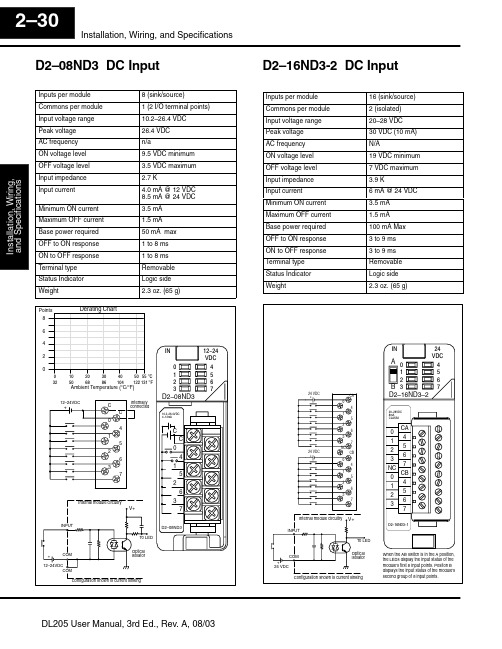
When the AB switch is in the A position, the LEDs display the input status of the module’s first 8 input points. Positon B displays the input status of the module’s second group of 8 input points.
24 VDC +
24 VDC +
CA 0
4 1
5 2
6 3
7 NC
CB
0 4
1 5
2 6
3 7
Internal module circuitry V+ INPUT
To LED
COM
+ 24 VDC
Optical Isolator
Configuration shown is current sinking
16 (sink/source) 2 (isolated) 20–28 VDC 30 VDC (10 mA) N/A 19 VDC minimum 7 VDC maximum 3.9 K 6 mA @ 24 VDC 3.5 mA 1.5 mA 100 mA Max 3 to 9 ms 3 to 9 ms Removable Logic side 2.3 oz. (65 g)
SZ05-L-STD-3 数传模块用户使用手册说明书
SZ05-L-STD-3数传模块用户使用手册V1.0上海顺舟智能科技股份有限公司更新日期:2017-11-10文档修订记录版本 变化状态 日期 作者V1.0 新增 2017-11-10 SHUNCOM目录一、产品概述 (4)1.1、性能特点: (4)1.2、规格型号: (4)1.3、技术参数: (5)2.1 产品外观图 (6)2.2 模块尺寸图 (6)2.3 模块引脚定义 (7)2.4 转接板 (8)2.5 评估板 (8)三、产品设置指南 (8)3.1 串口工具设置参数 (9)3.3 参数说明 (12)四、产品使用指南 (17)4.1 性能描述 (17)4.2 串口配置要求: (17)4.3透明数据传输 (17)4.4 SHUNCOM协议 (18)五、 一般故障清查: (19)六、联系方式 (19)一、产品概述1.1、性能特点:性能特点主要功能串口转无线功能强大全功能模块,具备中心、中继路由和终端设备功能通信距离最大视距传输距离100米抗干扰能力强 2.4G DSSS扩频技术串口应用透明方式或指令格式传输,最高波特率115200发送模式广播发送,固定目标或者协议类型发送模式可选节点类型中心节点、路由节点、终端节点可任意设置组网能力星型网、对等网、网状网网络容量16信道可选,65535个网络ID可任意设置,单网65535个节点1.2、规格型号:规格型号SZ05-L-XXX-XXX-X产品系列传输距离数据接口天线规格SZ05-L-STD-3(100米)TTL -PCB(内置天线)比如:型号SZ05-L-STD-3-TTL-PCB,表示SZ05-L系列无线数传模块、空旷场地传输距离为100米、TTL 接口、内置PCB天线。
1.3、技术参数:技术参数无线频率2400-2485M 2.4G ISM免费频段无线速率固定250K串口速率波特率1200-115200可设置调制方式DSSS 直序扩频信道模式16信道(间隔5M)信道检测CSMA/CA网络结构星型、对等、网状网(MESH)网络ID65535个可指定节点类型中心节点、路由节点、终端节点可设置发送模式透明传输或指令格式定位信息RSSIIO应用 12个IO口可扩展,支持开关量采集、高低点平输出、模拟量采集、PWM、DS18B20温度采集、dht21温湿度采集等功能输入电压DC 3.3V休眠电流 3UA发射功率0dbm接收灵敏度-95dbm接口类型TTL、IO设备天线 2.4G 内置PCB天线工作温度-40℃~+85℃工作湿度10%~90%不结露特殊说明本产品因尺寸过小,且无接插件针脚,建议客户购买专用SZ05-L 接插件底板二、外观结构尺寸图2.1 产品外观图2.2 模块尺寸图.2.3 模块引脚定义排序 标识 功能 备注1 PM1 PWM/AD采样 预留2 PM2 PWM/AD采样 预留3 AD1 AD采样 预留4 AD2 AD采样 预留5 AD3 AD采样 预留6 SLP/AD4 休眠脚 低电平休眠7 IO6/RUN 运行 LED8 IO7/NET 网络 LED9 NC 悬空10 SLP/AD4 休眠 低电平休眠11 PM4/485C PWM/AD采样 预留12 IO7/NET 网络 LED13 NC 悬空14 CFG 配置控制 低电平有效排序 标识 功能 备注1 PM3 PWM/AD采样 预留2 PM4/485C PWM/AD采样 预留3 IO6/RUN 运行 LED4 NC 悬空5 NC 悬空6 GND 电源地7 VCC 电源正 3.3V8 RX1 TTL电平 接用户TX9 TX1 TTL电平 接用户RX10 TCK 程序烧录引脚11 NC 悬空12 NC 悬空13 TMS 程序烧录引脚14 RST 复位 低电平有效2.4 转接板SZ05-L接插板项目 参数规格型号 SZ05-L 接插板适用模块 SZ05-L无线模块插件尺寸 27mm X 48mm (长X宽)功能描述 配合ZigBee评估板(见2.3 ZigBee评估板),方便对模块进行配置2.5 评估板ZigBee评估板项目 参数规格型号 Zigbee评估板适用模块 SZ05无线模块工作电压 DC 5~24V数据接口 RS232、RS485、USB功能描述 方便用户对模块进行配置,以减少因不当的接线而烧毁模块。
宝工 MT-2019 针型防误测三用电表 说明书

MT-2019Protective Function Analog MultimeterUser’s Manual1st Edition, 2019©2019Copyright by Prokit’s Industries Co., Ltd.INTRODUCTIONThis Multi-meter is an accurate, safe, battery operated, rear tilt-stand, easy to operate handheld instrument with robust protective holster alongside and the adjustable back tilt device with hook-up design. It can offer accurate, reliable measurement of DC/AC Voltage, DC Current, Resistance and Diode, LED, Transistor, Decibels, Continuity Buzzer and Capacitance with very high sensitive quality movement, and good-designed circuit, as well as colorful Aluminum dial plate etc. It has the perfect full overload & miss-used protection via Fuses, Oxide Varactor & Diodes. It is an ideal instrument for indoor use in the laboratory, school, workshop, hobby and home applications.CALIBRATIONΩ Zero Adjustor located at the right side of the panel, adjusting the meter pointer to the Zero mark on the right side of Ω scale of the meter dial when the test leads are touched together.Mechanical Adjustor Screw: located right below the center of the meter dial to set pointer to Zero mark at the left side of the scale.(-) Jack: Plug-in connector at the lower left on the panel for Black, negative test lead.(+) Jack: Plug-in connector at the lower right on the panel for Red, positive test lead.OPERATING INSTRUCTIONSCAUTIONWhen making voltage or current measurements, develop the habit of turning off all power to the circuit under test. Connect the test leads at the desired points in the circuit; then turn on the power while taking readings. Turn off the power before disconnecting the test leads from the circuit. INTERNAL BATTERY CHECKTo check the battery condition, insert the black test lead into the (-) jack. Set the range switch to the Ω X1 range position and short the ends of the two sides of the test leads. If the pointer can not be brought to the zero mark, replace the 1.5V cells or 9V cell. (See battery replacement.)BEFORE OPERATING1. Set the range switch to the proper position before making anymeasurement.2. Never apply more voltage or current than the rated value in everyposition.3. When the voltage or current to be measured it not known, always startwith the highest range.4. If meter indication is in the lower half of the scale and falls within therange of a lower scale, reset selector switch to the lower range forgreatest accuracy.5. If the meter won’t wotk at all, check the fuse located on the PCB. If it’sblown, replace it. (See fuse replacement.)6. Avoid placing the meter where extreme shock or continuous vibration isencountered and do not store in excessively hot or damp places.Although very rugged, the meter is a sensitive measuring device andshould be handled carefully & properly.7. Do not check resistance, transistor, diode, LED, or capacitance when livevoltage or current input across the circuit.8. When the meter is not in use, keep the selector switch to the “OFF”range position, this provides direct short across meter movement forminimum needle bounce when transporting meter.9. If you should accidentally apply excessive voltage or current on a certainrange, disconnect the leads from the circuot as quickly as possible,check instrument operation on that range by applying peoper input. If the meter does not operate peoperly, check fuse. If it is blown replace it.(See fuse replacement.)OPERATION PROCEDURESDC Voltage MeasurementWARNING: WITH EXTREME CARE WHEN MAKING MEASUREMENTS FOR HUGH VOLTAGE, AND DO NOT TOUCH TERMINAL OR PROBE ENDS.1. Set the selector switch to the appropriate DCV range to be used.2. Connect the BLACK test lea d to the “-COM” jack and the RED test leadto the “+” jack.3. If you know the polarity of the circuit to be tested, connect the blackprobe to the negative side.4. If you don’t know the polarity, connect the probes to opposite sides of thecircuit and watch the pointer. If it goes to the left, reverse the probes. The RED probe will be connected to the positive.5. Check the needle position and the get the reading on V.A scale.AC Voltage MeasurementWARNING: WITH EXTREME CARE WHEN MAKING MEASUREMENTS FOR HUGH VOLTAGE, AND DO NOT TOUCH TERMINAL OR PROBE ENDS.1. Set the selector switch to the appropriate ACV range to be used andconnect the test leads across the circuit or load under measurement.(Polarity of the test probes is unimportant on ACV test.)2. Connect the BLA CK test lead to the “-COM” jack and the RED test leadto the“+” jack.3. Check the needle position and the get the reading on V.A scale.DC Current MeasurementWARNING: DO NOT APPLY VOLTAGE TO MEASURING TERMINAL WHILE RANGE SWITCH IS IN CURRENT POSITION DO NOT ATTEMPT TO MEASURE AC CURRENT.1. Set the selector switch to the appropriate DC mA range to be used andconnect the test leads in series with the circuit or the load undermeasurement. If the pointer deflects to the left, reverse the probes.2. Connect the BL ACK test lead to the “-COM” jack and the RED test leadto the Red “+” jack for Current at/less than 0.25A.3. Check the needle position and the get the reading on V.A scale.Note:Excessive current input across mA range will blow the fuse that must be replaced by a same fuse rating 0.5A/250V.Note: If connected incorrectly with the voltage at these ranges, quickly remove the test leads from the circuit and can avoid the damage to thistester.(This tester can afford the voltage <250V DC/AC rms. for the period of 5 seconds max.)Resistance MeasurementWARNING: DO NOT APPLY VOLTAGE TO MEASURING TERMINAL WHILE RANGE SWITCH IS IN OHM POSITION.1. Set the selector switch to the appropriate Ω range to be used.2. Connect the BLACK test lead to the “-COM” jack and the RED test leadto the Red “+” jack.3. Short the leads by touching the probes together. Pointer should readzero at the right hand end of the uppermost scale, if it doesn’t, use the 0Ω adjust knob on the right hand of the panel to line up the pointer withz ero. (If pointer can’t be brought to zero, replace battery.)4. Connect the test leads across the resistance to be measured.5. Take reading on the top “Ω” scale and multiply it by the multiplicationfactor indicated by the selector switch.6. If there is little or no pointer movement from the left side of the scale,reset the selector switch to higher range. The effective reading scope on an Ω meter scale is within the area of between 25 degree of Arc left side to the Midscale and 25 degree right side to the Midscale.Note: If connected incorrectly with the voltage, quickly remove the test leads from the circuit as to avoid the damage to this tester. (This tester can afford the voltage <250V DC/AC rms. for the period of 5 seconds max.)Diode MeasurementSet the selector switch to the appropriate Ω range to be used.NOTE: To test the diode while current below 0.060 mA at X 10K range; current below 0.15 mA at X 1K range; current below 1.5 mA at X 100 range; current below 15 mA at X 10 range; current below 150 mA at X 1 range. For IF (forward current) TestPut the BLACK test lead to the “-COM” jack and the RED test lead to the Red “+” jack. And then connect the Black probe to the Positive terminal of the Diode, the Red probe to the Negative terminal of the Diode.For IR (reverse current) TestReverse the connection.1. Read the value IF or IR of the diode on the LI scale.2. Read the linear (forward voltage) VF of the diode on the LV scale.CONTINUITY TESTWARNING: DO NOT APPLY VOLTAGE TO MEASURING TERMINAL WHILE RANGE SWITCH IS IN OHM POSITION.Set the selector switch to the BUZZ range. Connect the test leads to two points of circuit. If the resistance is lower than 200 Ohm approx., the Beeper sounds.Note: Battery voltage is sufficient for Buzzer operation as long as the Zero Ohm pointer can be adjusted to the Zero scale place.Note: If connected incorrectly with the voltage, quickly remove the test leads from the circuit as to avoid damage to this tester.(This tester can afford the voltage <250V DC/AC rms. for the period of 5 seconds max.)Transistor hFE and LED TestSet the selector switch to the Ω X 10 range.For Measuring Transistor hFE1. Take note the type of transistor “PNP” or “NPN” and then insert thetransistor terminals of the Emitter, Base and Collector separately into the proper holes of the socket on the front panel.1. Read the approximate hFE Value directly at the hFE scale.Note: Current 10μA. VCE 2.8V.2. When the Base terminal cut, the value of Leak is Iceo for Transistor. For Measuring LEDInsert the transistor terminals directly into the “+” and “-” holes of thesocket on the front panel.And then check if the LED under testing is lighting.Battery Check1. This meter can come with two separate battery check ranges to testeither DC 1.5V or 9V batteries.2. Set the selector switch to the appropriate BATT range to be used.3. Connect the BLACK test lead to the “-COM” jack and the RED test leadto the Red “+” jack.4. Connect the Red test lead to the positive end of battery and the Blackone to the negative end of the battery to be measured.5. Take read ing on the “BATT” scale and check it good or bad as per whichportion indicated.(Note: the mark section of “?” shows that the battery may be starting to decay.)Note: If connected incorrectly with the voltage, quickly remove the test leads from the circuit as to avoid the damage to this tester.(This tester can afford the voltage <250V DC/AC rms. for the period of 5 seconds max.)Decibels Measurement1. Set the selector switch to AC 10V range.2. Connect the BLACK test lead to the “-COM” jack and the RED test leadto the “Output” jack.3. Connect the test leads to the measuring circuit, and then read the bottomRed dB scale.4. For more dB scope, change the selector switch to the others of ACVranges and make the same actions. Add the appropriate number of dBscale reading as noted on the chart below.Note: For absolute dB measurements, circuit impedance must be 600 Ohm. 0 dB = 1mw dissipated in a 600 Ohm impedance (equivalentWARNING: DO NOT APPLY VOLTAGE TO MEASURING TERMINAL WHILE MAKING ANY CAPACITANCE MEASUREMENTS.BEFORE TESTING ANY CAPACITORS, DISCHARGE THE CAPACITOR COMPLETELY.1. Set the selector switch to the Ω X 1K range.2. Connect the BLACK test lead to the “-C OM” jack and the RED test leadto the Red “+” jack.3. Connect the test leads to the capacitor to be measured (Note the polarityof capacitor).4. Watch the needle deflection to the right topside, and read the Red Cscale on the Dial.TROUBLESHOOTINGNevertheless, problems or malfunctions may occur.For this reason, the following is a description of how you can eliminate possible malfunctions by yourself:Replacement for Battery and/or Fuse should only be done after the test leads have been disconnected and POWER OFF.1. Battery Replacement1)Note the condition of the batteries using the procedure described above,if the battery needs to be replaced, remove the screw and open theupper cover of the battery cabinet on the rear case.2)Take off the spent batteries and replace them with a battery of the sametype. Observing polarity as indicated battery polarity marking on thebottom of the battery compartments.3)Replace the battery cabinet cover and tighten the screw.2. Fuse Replacement1)When the fuse needs replacement, use only UL-Listed 0.5A/250V fuseidentical in physical size to the original type Φ5 x 20 mm.2) Disassemble the side Holsters, and take off the screw, then open thewhole rear case. Remove the old fuse from its holder; install the new fuse into it.3) Replace the rear cover & Holsters, and tighten the screw.MT-2019指針型防誤測電錶操作使用說明書特點:本機是指針式,防誤測全保護,斜立型三用電錶(附晶體LED座。
- 1、下载文档前请自行甄别文档内容的完整性,平台不提供额外的编辑、内容补充、找答案等附加服务。
- 2、"仅部分预览"的文档,不可在线预览部分如存在完整性等问题,可反馈申请退款(可完整预览的文档不适用该条件!)。
- 3、如文档侵犯您的权益,请联系客服反馈,我们会尽快为您处理(人工客服工作时间:9:00-18:30)。
前言:本标定手册为德尔福小型发动机管理系统MT05使用。
具体的标定程序会由于标定工程师的经验,发动机的特殊用途,测试工具等其他因素的影响而有所不同。
因此本手册将提供一个典型的标定流程而非具体的操作命令。
在标定过程中,如果您遇到任何特殊问题,建议您联系德尔福EMS应用或系统工程师以获取更多建议。
目标:发动机在台架标定结束后,应该在任何转速和负荷情况下都能以优化的状态运行。
台架标定可以用来在测功机上对发动机进行性能评估测试。
标定结束的发动机可以被安装在整车上进行后续的整车标定。
基本知识:•理解发动机和发动机管理系统原理•理解基本的德尔福MT05控制逻辑•熟悉德尔福开发工具的基本操作步骤任务标定项目程序所需时间1 建立“Level0”标定传感器标定:•KtVIOS_T_IntakeAirTemp•KtVIOS_T_CoolantTemp•KfVIOS_MAP_SignConv_Slope•KfVIOS_MAP_SignConv_Intercept•KfVIOS_TPS_Slope•KfVIOS_Pct_TPS_RawIntercept点火系统标定:•KtSPRK_t_DwellIgnVoltRPM燃油供给系统标定:•KfFUEL_dm_InjectorFlow•KfEPSE_V_CylinderVolume•KtFUEL_t_InjOffset•KtFUEL_DC_FuelPumpDuty•KfFUEL_t_BPW_LowThrsh•KfFUEL_t_BPW_MinThrsh•KfHWIO_phi_BoundaryFraction•KtFUEL_phi_CrankEOIT•KtFUEL_phi_RunEOIT1.获取带有缺省标定值的基础标定2.在“desktop_cal.csv”中输入所有的传感器和执行器的标定值,然后导入到基础标定中3.如果德尔福EMS被使用,德尔福EMS工程师将提供相关标定值4.“level 0”标定应该能启动发动机并怠速•注意:在E22乙醇项目中,将KfFUEL_dm_InjectorFlow输入“gasoline injector flow *(13.4/14.6)”~1天进气系统标定:• KtVIOS_IAC_DsrdMtrPstn发动机结构标定:• KfHWIO_EngineConfig_inDegree • KeSYST_BaseCylinder• KbSYST_MAPCID_ENABLED重要注意事项:1. 在ECM 软件中根据以下规则定义发动机汽缸结构,这将确保发动机结构标定和实际的线束相一致。
A .独立进气道和节气门体式直列双缸发动机• 汽缸任意编号为1和2,MAP 传感器可以安装在任意一个汽缸的进气道内• 一旦汽缸编号确定,线束中将用同样编号连接喷油器和点火线圈• KfHWIO_EngineConfig_inDegree = engine_config_in_360_dergree 以保证两缸360度点火间隔 • 安装MAP 传感器的气缸定义为KeSYST_BaseCylinder 。
例如,左图所示KeSYST_BaseCylinder = cylinder_2 (cylinder_2 指物理2缸)B. 合并进气道和单节气门体式直列双缸发动机• 汽缸任意编号为1和2,MAP 传感器尽可能的靠近其中一个缸的进气口安装,用来检测该缸在进气行程时的压降• 一旦汽缸编号确定,线束中将用同样编号连接喷油器和点火线圈 • KfHWIO_EngineConfig_inDegree = engine_config_in_360_dergree 以保证两缸360度点火间隔 • 安装MAP 传感器的气缸定义为KeSYST_BaseCylinder 。
例如,左图所示KeSYST_BaseCylinder = cylinder_2 (cylinder_2 指物理2缸)1 2Injector 1 Ignition 1Ignition 2 Injector 2 MAP 1 2Injector 1Ignition 1 Ignition 2Injector 2 MAPC. 单缸发动机:(使用A 中发动机2缸相同的S/W 配置)• KfHWIO_EngineConfig_inDegree = = engine_config_in_360_dergree • KeSYST_BaseCylinder = cylinder_1 (cylinder_1 指物理1缸)D. 独立进气道和节气门体的V 列双缸发动机• 无论发动机生产商如何定义这两个气缸,ECM 软件将根据两缸的点火时间间隔确定汽缸编号 • 如果点火顺序是Cylinder 1 firing – 270 degrees – cylinder 2 firing – 450 degrees – cylinder 1 firing , KfHWIO_EngineConfig_inDegree = engine_config_in_270_450_dergree• 如果点火顺序是Cylinder 1 firing – 300 degrees – cylinder 2 firing – 420 degrees – cylinder 1 firing ,KfHWIO_EngineConfig_inDegree = engine_config_in_300_420_dergree• 汽缸2是参考缸,也就是说当它处在上止点时,曲轴传感器正好指在23X 目标盘第9齿的下沿。
• MAP 传感器可以安装在任意一个汽缸的进气道内。
• 安装有MAP 传感器的汽缸被定义为KeSYST_BaseCylinder 。
例如左图所示, KeSYST_BaseCylinder = cylinder_1 (cylinder_1 指物理1缸)1Ignition 1Injector 1 MAP 1Ignition 1Injector 2MAP2Ignition 2Injector 1E .合并进气道和单节气门体的V 列双缸发动机• 无论发动机生产商如何定义这两个气缸,ECM 软件将根据两缸的点火时间间隔确定汽缸编号 • 如果点火顺序是Cylinder 1 firing – 270 degrees – cylinder 2 firing – 450 degrees – cylinder 1 firing , KfHWIO_EngineConfig_inDegree = engine_config_in_270_450_dergree• 如果点火顺序是Cylinder 1 firing – 300 degrees – cylinder 2 firing – 420 degrees – cylinder 1 firing ,KfHWIO_EngineConfig_inDegree = engine_config_in_300_420_dergree• 汽缸2是参考缸,也就是说当它处在上止点时,曲轴传感器正好指在23X 目标盘第9齿的下沿。
• MAP 传感器尽可能的靠近其中一个缸的进气口安装,用来检测该缸在进气行程时的压降• 安装有MAP 传感器的汽缸被定义为KeSYST_BaseCylinder 。
例如左图所示, KeSYST_BaseCylinder = cylinder_1 (cylinder_1 指物理1缸)2.喷油器标定基于喷油器的动态流量特性。
喷油器流量曲线由喷油器应用工程师提供。
• KfFUEL_dm_InjectorFlow 是喷油器流量曲线线性部分 • KtFUEL_t_InjOffset 是流量曲线线性部分延长线在X 轴的截距• KfFUEL_t_BPW_LowThrsh 是喷油器针阀能够可靠打开的最小脉宽,等于喷油器特性曲线与X 轴截距减KtFUEL_t_InjOffset• KfFUEL_t_BPW_MinThrsh 是喷油器动态流量线性部分最小脉宽,低于此值喷油量将不能很好的控制,等于喷油器特性曲线线性区域的最小喷油脉宽减KtFUEL_t_InjOffset1Ignition 1Injector 2MAP2Ignition 2Injector 1 Flow g/sKtFUEL_t_InjOffsetPulse Width in msec(10 or 20 ms repetition rate)KfFUEL_dm_InjectorFlowKfFUEL_t_BPW_LowThrsh步骤任务标定项目程序所需时间2 安装发动机到测功机无 1.安装热电偶测量温度•各缸进气口温度•排气温度•机油温度•风冷发动机的发动机缸盖温度•其他发动机生产商指定的地方2.安装空燃比传感器测量每缸的空燃比3.爆震检测或监听装置4.排气背压测量5.燃油压力调节装置•推荐使用与实际用车相同的燃油供给硬件(燃油泵和压力调节器)•根据规范检验燃油系统压力是否正确6. 电源•推荐使用可调电源提供与实际用车相同的工作电压7. 检验点火时刻精确性•确认当参考缸在上止点时曲轴传感器在第9齿的下沿•如果可以获得上止点触发信号,控制点火角为0,确认点火时间与上止点触发信号同步。
1~2天2.A 确定发动机性能无 1.充分暖机2.保持节气门全开3.在每个发动机节点,调节点火角和空燃比,使得扭矩最大4.绘制功率和扭矩曲线,得到客户认可后再进行下一步标定~0.5天2.B 节气门调节无 1.充分暖机2.怠速运行(转速一般与技术协议保持一致)3.调节点火角到怠速点火角(通常无IACV时0-5,有IACV时5-15)4.确保空燃比在14.6附近5.调节旁通阀或步进电机以稳定发动机怠速与技术协议一致6.有IACV时步进电机步数应为25,否则调节拉盘螺钉直到步进电机移动到25步。
无IACV时旁通阀螺钉必须调节到合适的位置。
然后和截流阀体应用工程师一起测量节气门体漏气量。
~0.5天3 MAP ReadAngle, ChargeAir Temperature,第一轮VE 仅基于MAP的喷油系统:•KtVIOS_n_AXIS26_MAPReadAngle•KtVIOS_phi_MAPReadAngle_MAP基于MAP和TPS的喷油系统:•KtVIOS_n_AXIS9_MAPReadAngle•KtVIOS_phi_MAPReadAngle_TPS•KtVIOS_MAPEstimate•KtAIRF_Pct_VE_SmallLoad1•KtAIRF_Pct_VE_SmallLoad2常规标定:•KtAIRF_Pct_VE_Main1•KtAIRF_Pct_VE_Main2•KtAIRF_CAT_Factor1•KtAIRF_CAT_Factor2标定准备:•KtFUEL_n_AXIS17_AfrOpenLoop =14.6•KtVIOS_pct_TPS_IACComp = 0•KbSYST_MAPRead_TachoTgleEnbl= 1•IAT_ETS_Correction_For_CAT 在进行这步前先设为0•KbAIRF_VETableOption 选择基于vacuum或MAP•KfVIOS_p_AFLCStdBaro = Key onBaro•KfVIOS_n_BaroCalcRPM_Hi = 0以禁止running baro更新. 这在runningbaro更新逻辑被标定前使用基于vacuum的VE是十分重要的.•KtAIRF_n_AXIS17_VEMain1•KtAIRF_n_AXIS17_VEMain21. 充分暖机2. 调节步进电机位置到怠速步数(一般20-30)3. 选择KtVIOS_phi_MAPReadAngle_MAP 或KtVIOS_phi_MAPReadAngle_TPS中每个速度负荷节点,检验:•如果commanded AFR(AFR的目标值)不是14.6,在ITS内调节commanded AFR(AFR的目标值)到14.6•如果排气温度达到最大值,调节commanded (AFR的目标值)AFR偏浓以控制排气温度•如果检测到爆震,延迟点火正时以保护发动机•如果AFR_measrued(测量的AFR)不等于AFR_commanded,调节 VE 1&2使得AFR_measured = AFR_commanded4. 确定 MAP Read Angle: 使用ITS Slew 调节MAP Read Angle寻找最小的MAP值•建议不要寻找MAP值绝对最小点,而是寻找MAP值从低到高快速变化的开始点,并取其中最大的Read Angle 点记录。