氧化亚铜PPT课件
氧化亚铜晶体
氧化亚铜晶体
氧化亚铜晶体是各种颜色铜化合物的晶体形式,它是一种有序排
列的结构,表面有深红色到桔黄色的覆盖物,其中氧原子形成六角晶胞,铜原子结合在其中。
氧化亚铜晶体的主要成分是Cu2O,也称为黄铜,它是一种红色晶体,具有良好的光学特性,表面总是半干净的和发光的。
它的主要优
势是具有良好的耐热性,可避免由于温度过高而导致金属表面易腐蚀,耐碱性和耐候性良好,使其具有优良的耐磨蚀性。
此外,氧化亚铜晶
体具有优异的电导性,因此,它可以用作无线电网络、监控设备和抗
干扰措施。
氧化亚铜晶体的生产工艺主要包括沉淀反应、溶剂热法和非溶剂
热法。
沉淀反应是在弱酸溶液中将铜从氨氧化物中沉淀出来,然后将
生成的沉淀物舍入一种活性剂,最终加工成氧化亚铜晶体。
溶剂热法
是在有机溶剂中加热氨氧化铜,然后将溶解物与氯离子混合,最终结
晶得到氧化亚铜晶体。
而非溶剂热法则是将氨氧化铜加入热溶液中加热,控制温度升高到室温下析出氧化亚铜晶体。
氧化亚铜晶体被广泛应用于电子电路、眼镜行业等领域,它的优
越的光学性能、耐腐蚀性和耐温性等特点,使它在以上各个领域中受
到广泛的应用。
此外,它还可以用作滤光片、表面涂层、监控装置和
收纳电缆的护套材料。
总之,氧化亚铜晶体在化学、电子工程和光学工程领域都具有重
要的应用。
它的光学性能好,表面发红装饰性好,耐热耐腐性优秀,
容易加工,受到人们的欢迎和普遍应用。
氧化亚铜
氧化亚铜性状:深红色或深棕色结晶性粉末。
在潮湿空气中易氧化,溶于酸和浓氨水,不溶于水。
氧化亚铜为一价铜的氧化物,红色或暗红色八面立方晶系结晶性粉末。
相对密度6.0。
熔点1235℃。
在1800℃失去氧。
不溶于水和醇,溶于盐酸、氯化铵、氨水,微溶于硝酸。
溶于盐酸生成白色氯化亚铜结晶粉末。
遇稀硫酸和稀硝酸生成铜盐。
在空气中会迅速变蓝。
能溶于浓碱、三氯化铁等溶液中。
在湿空气中逐渐氧化成黑色氧化铜。
在酸性溶液中歧化为二价铜,说明在溶液中,二价铜离子的稳定性大于一价铜离子,例如氧化亚铜和硫酸反应,生成硫酸铜和铜。
Cu2O+H2SO4=CuSO4+Cu+H2O氧化亚铜与氨水和氢卤酸反应,因生成络合物,不歧化成二价铜和铜溶于浓氨溶液形成无色配合物[Cu(NH3)4]2+(铜铵离子),其在空气中被氧化为蓝色的[Cu(NH3)4(H2O)2]2+(二水合铜氨离子)氧化亚铜可溶于盐酸生成HCuCl2(氯化亚铜的配合物),也可溶于硫酸及硝酸分别形成硫酸铜及硝酸铜。
硫化亚铜【状态】:灰黑色结晶(正交晶体)或粉末或块状物。
【分子量】:159.158分解。
跟硝酸反应生成硝酸铜、硫和一氧化氮。
在隔绝空气下加热生成铜和硫化铜,在空气存在下生成氧化铜、硫酸铜和二氧化硫。
【矿藏】:在自然界以辉铜矿(也称辉铁矿)形式存在。
【制取】:由化学计量的铜和硫混合物在高真空封管内加热至400℃或由硫化铜在氢和硫化氢混合气流中加热至700℃而得,或者在硫酸铜溶液中加入硫代硫酸钠溶液共热也可制得。
【应用】用作制防污涂料、固体润滑剂、催化剂、太阳电池等。
磷化亚铜铜正一价磷负三价acyl group酰基不是一种区别有机物类别的基团。
有机化合物分子中的氮、氧、碳等原子上引入酰基的反应统称为酰化,但习惯上把碳原子上引入硝基、磺基和羧基(羧基可作为碳酸的酰基)的反应分别叫硝化、磺化和羧基化。
HO-NO2 硝酸-NO2 硝酰基HO-SO3 H 硫酸-SO3H 磺酰基HO-CO-OH 碳酸C=O 碳酰基(羰)Cl-SO-Cl 亚硫酰氯(氯化亚砜)S=O 亚硫酰基CH3COOH 乙酸CH3CO- 乙酰基Hofmann 重排(降解)酰胺用溴(或氯)在碱性条件下处理转变为少一个碳原子的伯胺:反应机理反应实例亲电试剂——在反应中能接受电子,并与之共有的物质。
氧化亚铜的形貌-概述说明以及解释

氧化亚铜的形貌-概述说明以及解释1.引言引言部分是文章的开头,用来介绍读者将要看到的内容。
在概述部分,您可以简要介绍氧化亚铜的形貌研究的背景和重要性。
下面是一个可能的编写内容供您参考:【1.1 概述】氧化亚铜是一种重要的无机功能材料,其形貌研究一直备受关注。
形貌是指物体外观的特征和表面结构的描述,对于了解材料的性质和应用具有重要意义。
特别是近年来,随着纳米技术的迅速发展,氧化亚铜的形貌研究日益受到关注。
氧化亚铜具有多种形貌,包括纳米粒子、片状结构、纳米线等。
这些不同的形貌在其物理化学性质上展现出了巨大的差异。
例如,纳米粒子形貌的氧化亚铜具有高比表面积和较好的催化性能,可应用于能源转换和环境治理领域。
而片状结构的氧化亚铜具有优异的电化学性能,在电池和超级电容器等领域有着广泛的应用。
因此,深入研究和理解氧化亚铜的形貌对于探索其性质和应用具有重要意义。
本文将对氧化亚铜的形貌进行探究和总结,主要包括氧化亚铜的形貌特点、形成机制以及相关应用等方面。
通过对不同形貌的氧化亚铜进行表征和分析,可以揭示其物理化学性质与形貌之间的关系,为进一步开发和应用氧化亚铜提供科学依据。
接下来,本文将按照以下结构进行叙述:首先,我们将在第二部分对氧化亚铜的形貌要点进行具体阐述,包括各种形貌的制备方法和关键特点。
然后,在第三部分中,我们将对这些形貌的特性进行总结,并对未来的研究方向和应用前景进行展望。
通过本文的探索和总结,相信能够为读者提供一个全面的认识和了解氧化亚铜形貌的机会,促进该领域的进一步发展和研究。
【参考】- A. Wang, X. Li, J. Yang, et al. (2017). Copper Oxide-based Materials: A Perspective on Achievements, Limitations, and Future Directions. Chemistry of Materials, 29(9), 3788-3832.- S. B. Ahn, S. J. Cho, J. M. Anderegg, et al. (2018). Copper Oxide Nanoparticles for Low-cost and Sustainable Photovoltaics: A Review. Applied Materials Today, 11, 1-16.1.2 文章结构本文将按照以下结构进行展开:第一部分为引言部分,包含三个小节。
氧化亚铜太阳能电池
一、所需材料
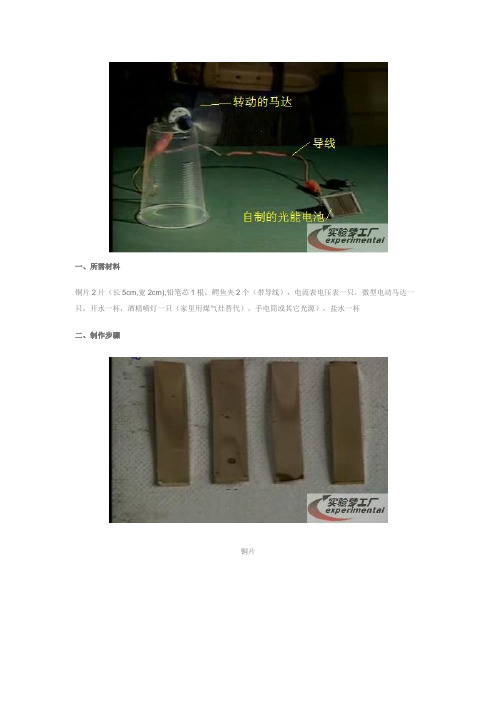
铜片2片(长5cm,宽2cm),铅笔芯1根,鳄鱼夹2个(带导线),电流表电压表一只,微型电动马达一只,开水一杯,酒精喷灯一只(家里用煤气灶替代),手电筒或其它光源),盐水一杯
二、制作步骤
铜片
把其中一片铜片放在喷灯上灼烧,表面会变成黑色(左图,生成了氧化铜),为进一步提高光电效率,还
要继续灼烧。
继续灼烧直到铜片有部分熔化(温度大概1000摄氏度)
烧红的铜片从火焰上移开后迅速放入冷水中
铜片从水中取出,表面就生成了红色的氧化亚铜(右侧图为表面生成黑色氧化铜的铜片对比)
用一只带导线的鳄鱼夹夹住铜片,另外一只夹住一根铅笔芯后靠在有氧化亚铜的一边
把两只鳄鱼夹的导线另外一端连接到电流表正负极上,由于室内有光,所有会显示大约10mA的电流
用手电筒照射,显示的电流会增加10倍左右,一只简单的光电池就成功了!
为提高效率,用同样的方法制作两片并用鳄鱼夹夹住后分别浸入到盐水中,当中用不透光的纸板隔开
导线的另外一端连到电流表的正负极上,在自然光下显示的电流
用手电筒照射其中一片铜片
照射另外一片。
氧化亚铜

氧化亚铜- 性质红色或暗红色八面立方晶系结晶性粉末。
相对密度6.O。
熔点1235℃。
在1800℃失去氧。
不溶于水和醇,溶于盐酸、氯化铵、氨水,微溶于硝酸。
溶于盐酸生成白色氯化亚铜结晶粉末。
遇稀硫酸和稀硝酸生成铜盐。
在空气中会迅速变蓝。
能溶于浓碱、三氯化铁等溶液中。
在湿空气中逐渐氧化成黑色氧化铜。
剧毒!氧化亚铜- 制法1.干法:铜粉经除杂质后与氧化铜混合,送入煅烧炉内加热到800~900℃煅烧成氧化亚铜。
取出后,用磁铁吸去机械杂质,再粉碎至325目,制得氧化亚铜成品。
如果采用硫酸铜为原料,则先用铁将硫酸铜中的铜还原出来,以后的反应步骤与以铜粉为原料法相同。
2.葡萄糖还原法;将硫酸铜溶液与葡萄糖混合后加入氢氧化钠溶液进行反应,生成氧化亚铜,经过滤、漂洗、烘干粉碎制得氧化亚铜产品。
3.电解法:在铁制壳体内衬聚氯乙烯的电解槽中,以浇铸铜板作阳极,紫铜板作阴极,用铬酸钾作添加剂,食盐溶液作电解液,其中含氯化钠为290~310g/L、铬酸钾为0.3~0.5g/L、温度70~90℃、pH值8~12、电流密度1500A/m2的条件下进行电解,生成氧化亚铜,经沉淀分离、漂洗、过滤、干燥制得氧化亚铜。
氧化亚铜- 用途用于制造船底防污漆(用来杀死低级海生动物),杀虫剂,以及各种铜盐、分析试剂、红色玻璃。
还用于电器工业中的整流电镀。
也用作陶瓷和搪瓷的着色剂。
氧化亚铜- 安全性用内衬聚乙烯塑料袋的铁桶包装,每桶净重25kg或50kg。
应有"剧毒”标志。
属毒害品。
危规编号:参照GB 6.1类61519. UN NO. 2765、3010、2766;IMDE CODE 6221、3270、6220、6219页,6.1类。
贮存于干燥、通风良好的库房内,不得与氧化剂混放。
容器必须密封,防止与空气接触变成氧化铜而降低使用价值。
不可与强酸、强碱及食用物品共贮混运。
装卸时要轻拿轻放,防止包装破损。
失火时可用水、砂土、各种灭火器扑救。
氧化亚铜光化学反应
Crystal Faces of Cu 2O and Their Stabilities in Photocatalytic ReactionsZhaoke Zheng,†Baibiao Huang,*,†Zeyan Wang,†Meng Guo,‡Xiaoyan Qin,†Xiaoyang Zhang,†Peng Wang,†and Ying Dai ‡State Key Laboratory of Crystal Materials,Shandong Uni V ersity,Jinan 250100,P.R.China,and School of Physics,Shandong Uni V ersity,Jinan 250100,P.R.ChinaRecei V ed:May 5,2009;Re V ised Manuscript Recei V ed:June 20,2009Cu 2O microcrystals with well-formed facets were synthesized by a simple hydrothermal method.The surface stabilities and photocatalytic properties of Cu 2O microcrystals were systematically investigated.Cu 2O {100}and {110}facets gradually disappear and transform into nanosheets during the photodegradation of methyl orange (MO)dye.With the increase of irradiation time,Cu 2O microcrystals completely transform into nanosheets with {111}facets.The finally formed nanosheets exhibit stable photocatalytic activities.On the basis of both experimental analysis and theoretical calculations,a novel model of charge separation among crystal faces was proposed and the morphology transformation mechanism accompanied by MO bleaching was discussed.It is concluded that Cu 2O exposing {111}facets can be used as a stable photocatalyst.IntroductionCuprous oxide (Cu 2O),an important p-type semiconductor with a direct band gap of 2.0eV,has attracted extensive attention for its applications in solar energy conversion,gas sensors,electronics,and magnetic storage,etc.1-3Recently,photocata-lytic properties of Cu 2O have also been studied.It is demon-strated to be a promising photocatalyst in directly water splitting and organic contamination degradation under visible-light irradiation.4,5Additionally,Cu 2O can effectively adsorb mo-lecular oxygen,6which can scavenge the photogenerated electrons to restrain the recombination of electron -hole pairs,and consequently improve the photocatalytic efficiency.Fur-thermore,the intrinsic properties of Cu 2O,such as low toxicity,good environmental acceptability,and low price,7make it a potential candidate for photocatalytic applications.Unfortu-nately,the photoinstability of Cu 2O greatly hindered its further applications in photocatalysis.According to Bessekhouad et al.report,Cu 2O can be easily deactivated by photocorrosion when combined with TiO 2.8Huang et al.also reported that Cu 2O can be photocorroded after irradiation for several hours on the degradation of methyl orange (MO).9Therefore,it is of great importance to investigate the stability of Cu 2O.Because of the anisotropy of crystals,people found different crystal faces usually exhibit different properties,such as stabilities,activities,etc.In the past few decades,great achieve-ments have been made by investigating the chemical properties of definite crystal faces by employing bulk single crystals.10-12Recently,investigations on the highly active surfaces of pho-tocatalysts became a hot spot in photocatalytic research.13-18Many photocatalysts have been investigated and showed dif-ferent photoactivities on different faces,such as {001}facets of anatase TiO 2showed higher activity than {101}facets,octahedral Cu 2O with exposed {111}facets exhibited much higher photocatalytic activity than cubes,etc.19-21However,the stabilities on different faces of photocatalysts have not been extensively studied yet.In this study,Cu 2O microcrystals were synthesized by a simple hydrothermal method.The stabilities of different crystal faces and photocatalytic properties have been systematically studied.Cu 2O {100}and {110}facets gradually transform into nanosheets during the photodegradation of methyl orange (MO)under visible light irradiation,and finally Cu 2O microcrystals change into nanosheets with {111}facets mainly exposed.At the initial runs of photocatalytic experiments,Cu 2O microcrys-tals show highly efficient catalytic activity,and the probable reason was discussed.The finally formed nanosheets exhibit stable photocatalytic activity.A novel model of charge separa-tion among crystal faces was proposed on the basis of X-ray diffraction (XRD),scanning electron microscopy (SEM),and first-principles density function theory (DFT)calculations,and the morphology transformation mechanism accompanied by MO bleaching was also discussed.First-principles DFT calculations were carried out for a model structure constructed with a 48-atom 2×2×2supercell to confirm the suggestions of our experimental work that charge separation among crystal faces is energetically favorable.Experimental SectionPreparation.Cu 2O microcrystals were synthesized by a simple hydrothermal method.Cu(CH 3COO)2·H 2O and CH 3COOH of AR grade were employed as starting materials.22Details of the synthetic procedures were described as follows.First,2.395g of Cu(CH 3COO)2·H 2O was dissolved into 60mL of deionized water to form a clear solution.Then,1mL of CH 3COOH was added into the solution under continuous stirring to form the precursor solution.The precursor solution was transferred into an 80mL Teflon-lined stainless steel autoclave,which was then maintained at 200°C for 27h.The red products collected from the bottom of the container were washed with deionized water for several times and dried in a vacuum oven at 60°C for 5h.The N-doped TiO 2reference photocatalyst was prepared by nitridation of commercially available TiO 2powder (surface area 50m 2g -1)at 773K for 10h under NH 3flow (flow rate of 350mL min -1).23Photocatalytic Reactions.MO dye was chosen to evaluate the photocatalytic properties of our samples.In a typical*To whom correspondence should be addressed.Phone:+86-531-8836-6324.Fax:+86-531-8836-5969.E-mail:bbhuang@.†State Key Laboratory of Crystal Materials.‡School of Physics.J.Phys.Chem.C 2009,113,14448–144531444810.1021/jp904198d CCC:$40.75 2009American Chemical SocietyPublished on Web 07/06/2009reaction,0.1g as-prepared Cu2O powders were dispersed in a Pyrex glass reactor(with a30cm2cross section and5cm height) containing100mL MO solutions(with a concentration of20 mg L-1).24The suspension was then kept in the dark with agitation for4h to obtain an adsorption equilibrium prior to illumination.The photocatalytic reactions were carried out at room temperature,using a300W Xe arc lamp(PLS-SXE300, Beijing Trusttech Co.Ltd.)equipped with an ultraviolet cutoff filter as the light source(λ>400nm).MO concentration in the reactor was tuned to20mg L-1every60min.At given intervals (20min),aliquots(5mL)of the solution were sampled and analyzed by UV/vis spectrophotometer(UV-7502PC,Xinmao, Shanghai).After given runs of photocatalytic reactions,the suspensions werefiltered and the resulting precipitates were collected for further characterization.For comparison,the decomposition experiment of MO dye over N-doped TiO2as a reference was carried out under identical conditions as the Cu2O samples.The analysis of H2O2in solution was carried out by the iodidemethod.30At given intervals(15min),aliquots(1.5mL)of the irradiated Cu2O(1g L-1)suspensions werefiltered,and then 0.75mL of0.1M potassium biphthalate was added.At t)0 min,0.75mL of iodide reagent(0.4M potassium iodide,0.06 M NaOH,≈10-4M ammonium molybdate)was added,and the absorbance of the solution atλ)352nm(the characteristic absorption wavelength of I3-ion)was recorded in30s.The amount of H2O2is direct proportional to that of I3-.5 Characterization.The structures and morphologies of Cu2O, before and after visible light irradiation,were investigated by XRD(Bruker D8-advanced X-ray powder diffractometer with Cu K R radiation)and SEM(Hitachi S-4800microscope),and the binding energies of Cu2p3/2states for our samples were characterized by using X-ray photoelectron spectroscopy(XPS) (VG Micro Tech ESCA3000X-ray photoelectron spectroscope using monochromatic Al K R with a photon energy of1486.6 eV at a pressure of>1×10⁻⁹Torr,a pass energy of40eV,an electron takeoff angle of60°,and an overall resolution of0.05 eV).The XPS spectra werefitted using a combined polynomial and Shirley-type background function.Results and DiscussionsCharacterization of Morphology Transformation.Figure 1a-c shows the XRD patterns of Cu2O irradiated in MO dye for0,1,and16h,respectively.From thisfigure,we can clearly see that all samples can be indexed to cubic Cu2O phase with lattice constant of a)4.252Å(JCPDS:1-1142).In addition, no other phases,such as CuO and Cu,are traced.For as-prepared samples,the diffraction peak of(200)planes is much stronger than that of(111)planes as shown in Figure1a.That indicates Cu2O microcrystals synthesized by hydrothermal method have a relatively high percentage of{200}facets.However,after irradiation in MO solution for1h,the diffraction intensity of (111)planes increases and become much stronger than that of (200)planes(Figure1b).When Cu2O microcrystal was irradi-ated in MO solution for16h,the diffraction intensity of different planes has greatly changed comparing to the as-prepared samples.The(111)peak dominates,and the ratio of the diffraction intensity between the other planes and(111)planes become much lower.It is suggested that a morphology transformation may exist during the photodegradation process. The SEM images shown in Figure2confirm the assumption of morphology transformation.After irradiation under visible light for1h,Cu2O{100}and{110}facets gradually transform into nanosheets(see Figure2c and d).When the irradiation time is as long as16h,Cu2O microcrystals completely change into nanosheets.Considering the XRD analysis above,it is confirmed that thefinally formed Cu2O nanosheets are primarily dominated by{111}facets.This experiment was also carried out in the dark,and no morphology transformation was observed.There-fore,the morphology transformation of Cu2O is a photoinduced process.To investigate the effect of MO in the morphology transformation,Cu2O samples irradiated without MO were also investigated.As shown in Figure3,no nanosheets are formed and Cu2O{100}facets are slightly photocorroded,which may be due to the oxidization by the photoinduced holes. Photodegradation of MO.Figure4represents the variation of MO concentration versus reaction time over the catalysts. Prior to irradiation,the MO solution mixed with the catalyst was kept in the dark for4h in order to eliminate other effects for MO bleaching,such as adsorption and reaction without light. The concentration of MO solution slightly decreases while it is kept in the dark,which is due to the adsorption of MO by the catalysts.As a comparison,MO degradation over N-doped TiO2 (1g L-1)was also carried out under identical conditions. Although the as-prepared Cu2O microcrystals have lower surface areas,we surprisinglyfind that they show much higher photo-catalytic activities for MO bleaching.After irradiated under visible light for60min,the MO dye is completely bleached over Cu2O for thefirst run,while only40%of MO dye is bleached over N-doped TiO2.However,as the irradiation time increases,the photocatalytic activity of Cu2O gradually de-creases.After16runs of MO bleaching,Cu2O microcrystals completely transform into nanosheets(Figure2e and f),and the photocatalytic activity of nanosheets is only half of that from microcrystals in thefirst run.However,it still shows higher activities than N-doped TiO2,which may be due to the high percentage of exposed{111}facets.21Cu2O nanosheets remain stable at subsequent runs of MO bleaching(see Figure5).The XRD pattern of the sample at the end of the repeated bleaching experiment also shows a pure phase of Cu2O.It indicated that thefinally formed Cu2O nanosheets with{111}facets mainly exposed can be used as a stable photocatalyst.Theoretical Calculation.In order to investigate the anisot-ropy of Cu2O shown in Figure2c,the surface energies(γ)of Cu2O(100),(110),and(111)surfaces were calculated on the basis of thefirst principles method(Table1).Because of the diverse atomic arrangements characteristic of Cu2O(111) surfaces,it can be divided into two kinds of surfaces,(111) and(111)*,respectively.As Cu2O(111)*surfaces presentthe Figure1.XRD patterns of Cu2O irradiated for(a)0,(b)1,and(c) 16h in MO solution.Crystal Faces of Cu2O and Their Stabilities J.Phys.Chem.C,Vol.113,No.32,200914449highest surface energies,this kind of surfaces are hard to appear.Therefore,only three kinds of surfaces are considered in this paper,Cu 2O (111),(110),and (100)surfaces,respectively.Contrasting the surface energies of these three kinds of surfaces,it is concluded that Cu 2O (111)surfaces with the lowest surface energies are of the most stable,second is Cu 2O (110)surfaces,and Cu 2O (100)surfaces are of the most active,which is consistent with the SEM image shown in Figure 2c.To explore the electronic structures of different crystal faces and understand the phenomena of morphology transformation occurred on different Cu 2O surfaces,the density of states (DOS)of Cu 2O was subsequently calculated using first-principles DFT.25,26Figure 6represents the calculated band structure of Cu 2O.As shown in the figure,bulk Cu 2O is a semiconductor with a theoretical band gap of 0.64eV,which is consistent with the value calculated by Soon et al.27Figure 2.SEM images of Cu 2O samples irradiated for (a,b)0,(c,d)1,and (e,f)16h.(d)The higher magnification image of the (100)facet is shown in Figure2c.Figure 3.SEM images of Cu 2O samples irradiated for 5h without MO.14450J.Phys.Chem.C,Vol.113,No.32,2009Zheng et al.Different crystal faces possess different surface energy levels of conduction and valence bands due to the atomic arrangements characteristic of these faces.28For anatase TiO 2,Ohno et al.experimentally verified that the oxidation site is mainly on the {001}face and the reduction site is mainly on the {011}face.29According to the calculation of Gong et al.,the valence band of TiO 2(001)extends to somewhat higher energies with respect to (101).19This agreement between experiment and theory suggests that the difference in the energy levels between crystal faces can drive electrons and holes to different crystal faces,leading to the separation of electrons and holes.From the DOS of different Cu 2O surfaces,it is evident that the valence band of Cu 2O (100)and (110)extends to higher energies with respect to Cu 2O (111).According to the SEM image shown in Figure 2b and the DOS of Cu 2O,a novel model of charge separationamong different crystal faces was proposed.When irradiated by visible light,Cu 2O can generate electrons and holes and photogenerated holes on {111}facets will transfer to {100}and {110}facets,while the electrons on {100}and {110}facets will migrate to {111}facets,which is energetically favorable.That means,the oxidation sites are mainly on the {100}and {110}facets and the reduction sites are mainly on the {111}facets.In this work,the crystal faces of Cu 2O were well formed and the photogenerated electrons and holes can be efficiently separated owning to the different band levels of Cu 2O surfaces (Figure 6).This separation is probably the key to the high photocatalytic activity of Cu 2O microcrystals at the initial runs.Along with the increase of irradiation time,Cu 2O {100}and {110}facets gradually disappear.The separation of photoge-nerated charges among different facets is restrained,and those electrons and holes could recombine easily.Therefore,the photocatalytic activity of Cu 2O gradually decreases as the times of photocatalytic experiments increase.The decrease of pho-tocatalytic activity further supports the model of charge separa-tion among different crystal faces.Mechanism Discussion.On the basis of the results of XRD,SEM,and first-principles DFT calculations,a morphology transformation mechanism was proposed (Figure 7).When Cu 2O microcrystals are irradiated by visible light,electrons and holes are generated.Abundant electrons accumulated on Cu 2O{111}Figure 4.MO (20mg L -1)photodegradation over N-doped TiO 2(9)Cu 2O-17th run (b )and Cu 2O-first run (2)under visible light (λ>400nm)at room temperature in air.MO concentration in the reactor was tuned to 20mg L -1every 60min.Figure 5.MO (20mg L -1)degradation over Cu 2O during repeated photooxidation experiments under visible light.TABLE 1:Calculated Surface Energies of Cu 2O (100),(110),and (111)Surfacestotal energy (eV)energy ref-bulk (eV)area (Å2)energy classical (J m -2)relaxedbulk(Cu 2O)2*8-217.98453018.2294842surface-100-215.26799 2.71653818.2294842 1.193728707surface-110-214.84804 3.13648825.78038280.974582261surface-111-215.31612 2.66840831.57439040.676988814surface-111*-212.393355.59117831.57439041.418510573Figure 6.Total DOS of Cu 2O.Figure 7.Schematic diagram showing charge separation among different crystal faces and regeneration of Cu 2O nanosheets.Crystal Faces of Cu 2O and Their Stabilities J.Phys.Chem.C,Vol.113,No.32,200914451facets,meanwhile,holes accumulated on Cu 2O {100}and {110}facets.As Cu 2O has a powerful adsorption for molecular O 2,the electrons accumulated on Cu 2O {111}facets can be scavenged by adsorptive O 2to yield O 2-,and O 2-further reacts with H 2O and electrons to produce hydrogen peroxide (H 2O 2)and hydroxyl radical (•OH),9,30which can effectively bleach the MO dye.Meanwhile,Cu 2O {100}and {110}facets are oxidized to CuO by the holes accumulated on them.When the intermedi-ate CuO is irradiated by visible light,it generates electrons and holes,31and the photogenerated holes could be captured by MO.As the holes are consumed,CuO formed on {100}and {110}facets is reduced back to Cu 2O.Then Cu 2O nanosheets are ultimately formed.With the increase of irradiation time,Cu 2O microcrystals completely transform into nanosheets.To support the mechanism proposed above,the measurement of H 2O 2generated in the system was carried out by iodide method.The iodide method allows one to distinguish between H 2O 2and organic peroxides since the latter react more slowly with the molybdenum-iodide system.30Figure 8shows the relationship between time and absorbance at 352nm of the solution containing Cu 2O microcrystals.Under the irradiation of visible light,the absorbance of the solution sampled at given intervals gradually increases.This demonstrates that there are incremental amounts of H 2O 2evolved from the system.To confirm the existence of Cu(II)in the morphology transformation process,XPS was employed to obtain the surface information of Cu 2O.XPS spectra of Cu 2p 3/2measured for the samples under different irradiation conditions are displayed in Figure 9.The XPS spectra are charge corrected to the adventi-tious C 1s peak at 284.6eV.The peaks located at 932.2and 932.4eV can be attributed to the Cu(I)in Cu 2O according to the reported binding energy of Cu 2O at 932.4or 932.5eV,32-34and the peaks located at 934.2and 934.9eV are also close to the literature date of CuO surface phase at a range of 933.4-934.6eV.35-40According to the XRD pattern of the samples (Figure 1),the products before and after light irradiation are all pure phase of Cu 2O;however,the trace of element information on the surface can not be detected by XRD.Through the surface compositional analysis,more precise information can now be acquired.The XPS spectra of the initial product show that the sample surfaces are only composed of Cu 2O (Figure 9a).After irradiated in MO solution for 10h,Cu 2p 3/2spectra can be fitted into two peaks corresponding to Cu(I)and Cu(II)(Figure 9b),which confirms the existence of Cu(II)inthe process of morphology transformation and MO bleaching.To further explore the effect of Cu(II)on morphology trans-formation,a comparison experiment was carried out in deionized water under identical conditions.After irradiated in deionized water for 10h,the main phase on the surface becomes CuO.And the high percentage of Cu(II)on the surface is due to the absence of MO dye.Without MO,the holes generated at the VB top of the intermediate CuO can not be consumed,and then CuO can not be reduced back to Cu 2O,which leads to the high percentage of Cu(II)on the surface.Therefore,the measurement of H 2O 2and the XPS analysis further supports the mechanism of morphology transformation.ConclusionsWell-faceted Cu 2O single crystals were synthesized by a simple hydrothermal method.During the process of MO bleaching under visible light irradiation,Cu 2O {100}and {110}facets transform into nanosheets.With the increase of irradiation time,Cu 2O microcrystals completely change into nanosheets.Cu 2O microcrystals exhibit considerable photocatalytic activity in the first runs,which is ascribed to the charge separation among crystal faces.In addition,the finally formed Cu 2O nanosheets present stable photocatalytic activity due to the mainly exposed {111}facets.A model for charge separation and a mechanism for morphology transformation have been proposed,and they were further verified by our DFT calculations and XPS analysis.It is concluded that Cu 2O can be used as a stable photocatalyst when {111}facets are exposed.On the other hand,the model of charge separation among crystal faces provides a new way to improve photocatalytic efficiency.Acknowledgment.This work was financially supported by research grants from the National Basic Research Program of China (No.2007CB613302)and the National Natural Science Foundation of China (Nos.50721002and 10774091).References and Notes(1)Briskman,R.N.Sol.Energy Mater.Sol.Cells 1992,27,361.(2)Zhang,J.T.;Liu,J.F.;Peng,Q.;Wang,X.;Li,Y.D.Chem.Mater.2006,18,867.(3)Poizot,P.;Laruelle,S.;Grugeon,S.;Dupront,L.;Taracon,J.M.Nature 2000,407,496.(4)Hara,M.;Kondo,T.;Komoda,M.;Ikeda,S.;Shinohara,K.;Tanaka,A.;Kondo,J.N.;Domen,mun.1998,3,357.Figure 8.Relationship between irradiation time and absorbance at 352nm of the solution.Inset:Changes to the UV/vis spectrum of the solution as a function of irradiationtime.Figure 9.XPS spectra of Cu 2p 3/2for Cu 2O under different irradiation conditions.The labels a,b,and c indicate the as-prepared Cu 2O without light irradiation,irradiated in MO solution,and deionized water for 10h,respectively.14452J.Phys.Chem.C,Vol.113,No.32,2009Zheng et al.(5)Zhang,Y.G.;Ma,L.L.;Li,J.L.;Yu,Y.En V iron.Sci.Technol. 2007,41,6264.(6)Li,J.L.;Liu,L.;Yu,Y.;Tang,Y.W.;Li,H.L.;Du,F.P. mun.2004,6,940.(7)Siripala,W.;Ivanovskaya,A.;Jaramillo,T.F.;Baeck,S.H.; McFarland,E.W.Sol.Energy Mater.Sol.Cells2003,77,229.(8)Bessekhouad,Y.;Robert,D.;Weber,J.V.Catal.Today2005,101, 315.(9)Huang,L.;Peng,F.;Yu,H.;Wang,H.J.Solid State Sci.2009,11, 129.(10)Kiskinova,M.Chem.Re V.1996,96,1431.(11)Somorjai,G.A.Chem.Re V.1996,96,1223.(12)Seker,F.;Meeker,K.;Kuech,T.F.;Ellis,A.B.Chem.Re V.2000, 100,2505.(13)Yang,H.G.;Sun,C.H.;Qiao,S.Z.;Zou,J.;Liu,G.;Smith,S.C.; Cheng,H.M.;Lu,G.Q.Nature2008,453,638.(14)Kislov,N.;Lahiri,J.;Verma,H.;Goswami,D.Y.;Stefanakos, Elias.;Batzill,ngmuir2009,25,3310.(15)Kawano,K.;Komatsu,M.;Yajima,Y.;Haneda,H.;Maki,H.; Yamamoto,T.Appl.Surf.Sci.2002,189,265.(16)Gong,X.Q.;Selloni,A.;Batzill,M.;Diebold,U.Nat.Mater.2006, 5,665.(17)Peng,C.W.;Richard-Plouet,M.;Ke,T.Y.;Lee,C.Y.;Chiu,H.T.; Marhic,C.;Puzenat,E.;Lemoigno,F.;Brohan,L.Chem.Mater.2008,20, 7228.(18)Brinkley,D.;Engel,T.J.Phys.Chem.B2000,104,9836.(19)Gong,X.Q.;Selloni,A.J.Phys.Chem.B2005,109,19560.(20)Han,X.G.;Kuang,Q.;Jin,M.S.;Xie,Z.X.;Zheng,L.S.J.Am. Chem.Soc.2009,131,3152.(21)Xu,H.L.;Wang,W.Z.;Zhu,W.J.Phys.Chem.B2006,110, 13829.(22)Yu,H.G.;Yu,J.G.;Liu,S.W.;Mann,S.Chem.Mater.2007,19, 4327.(23)Wang,P.;Huang,B.B.;Qin,X.Y.;Zhang,X.Y.;Dai,Y.;Wei, J.Y.;Whangbo,M.-H.Angew.Chem.,Int.Ed.2008,47,7931.(24)Wang,Z.Y.;Huang,B.B.;Dai,Y.;Qin,X.Y.;Zhang,X.Y.; Wang,P.;Liu,H.X.;Yu,J.X.J.Phys.Chem.C2009,113,4612.(25)Yang,K.S.;Dai,Y.;Huang,B.B.;Whangbo,M.-H.J.Phys.Chem. C2009,113,2624.(26)Zou,Z.G.;Arakawa,H.J.Photochem.Photobiol.A2003,158, 145.(27)Soon,A.;Todorova,M.;Delley,B.;Stampfl,C.Phys.Re V.B2006, 73,165424.(28)Oliver,P.M.;Watson,G.W.;Kelsey,E.T.;Parker,S.C.J.Mater. Chem.1997,7,563.(29)Ohno,T.;Sarukawa,K.;Matsumura,M.New.J.Chem.2002,26, 1167.(30)Kormann,C.;Bahnemann,D.W.;Hoffmann,M.R.En V iron.Sci. Technol.1988,22,798.(31)Bandara,J.;Guasaquillo,I.;Bowen,P.;Soare,L.;Jardim,W.F.; Kiwi,ngmuir2005,21,8554.(32)Yoon,K.H.;Choi,W.J.;Kang,D.H.Thin Solid Films2000, 372,250.(33)Wang,W.Z.;Wang,G.H.;Wang,X.S.;Zhan,Y.J.;Liu,Y.K.; Zheng,C.L.Ad V.Mater.2002,14,67.(34)Teo,J.J.;Chang,Y.;Zeng,ngmuir2006,22,7369.(35)Espins,J.P.;Morales,J.;Barranco,A.;Caballero,A.;Holgado, J.P.;Gonzlez-Elipe,A.R.J.Phys.Chem.B2002,106,6921.(36)Zhu,J.W.;Chen,H.Q.;Liu,H.B.;Yang,X.J.;Lu,L.D.;Wang, X.Mater.Sci.Eng.,A2004,384,172.(37)Wang,W.;Liu,Z.;Liu,Y.;Xu,C.;Zheng,C.;Wang,G.Appl. Phys.A:Mater.Sci.Process.2003,76,417.(38)Xu,J.F.;Ji,W.;Shen,Z.X.;Tang,S.H.;Ye,X.R.;Jia,D.Z.; Xin,X.Q.J.Solid State Chem.1999,147,516.(39)Wang,H.;Xu,J.Z.;Zhu,J.J.;Chen,H.Y.J.Cryst.Growth2002, 244,88.(40)Brookshier,M.A.;Chusuei,C.C.;Goodman,ngmuir 1999,15,2043.JP904198DCrystal Faces of Cu2O and Their Stabilities J.Phys.Chem.C,Vol.113,No.32,200914453。
物质拓展系列——氧化亚铜

物质拓展系列——氧化亚铜例1.氢气还原氧化铜生成红色固体,这些红色固体是什么物质?某科学兴趣小组查阅资料得知,反应温度不同,氢气还原氧化铜的产物可能是Cu或Cu2O,Cu和Cu2O均为不溶于水的红色固体,但氧化亚铜能与稀硫酸反应,化学方程式为:Cu2O + H2SO4═ CuSO4 + Cu + H2O。
为探究反应后的红色固体中含有什么物质?他们提出了以下假设:假设一:红色固体只有Cu假设二:红色固体只有Cu2O假设三:红色固体中有Cu和Cu2O请回答有关问题:(1)取少量红色固体,加入足量的稀硫酸,若无明显现象,则假设成立;若看到溶液变成蓝色,且仍有红色固体,则能否支持假设三?(选填“能”或“不能”)(2)现将3克红色固体加入足量的稀硫酸中,反应后的溶液过滤,称得烘干后的滤渣质量为1.4克,则原红色固体中含有什么物质?。
例2.我国劳动人民早在五千年前就会使用木炭炼铜。
在化学实验室里模拟炼铜,既可用传统的实验装置(见图甲),又能用改进的微型实验装置(见图乙)。
化学兴趣小组采用图乙装置,开展以下探究活动。
【提出问题】木炭与CuO反应所得红色固体中含有什么物质?【查阅资料】(1)木炭与CuO的化学反应方程式为:,若该反应进行的不彻底,产物中还有氧化亚铜(Cu2O)。
(2)Cu2O是红色固体,能与稀硫酸反应:Cu2O + H2SO4 = Cu + CuSO4 + H2O【作出猜想】红色固体的成分:①全部是Cu;②全部是Cu2O;③。
【实验探究】(1)取木炭、CuO两种黑色粉末适量,再加少许CaC12(能降低反应温度,加快反应速率)均匀混合,然后将黑色粉末装入长柄V形玻璃管的直管内。
(2)按图乙连好实验装置,然后加热反应物;2分钟后,黑色粉末出现红热现象,同时澄清石灰水,此时停止加热。
(3)待玻璃管冷却后,提取里面的红色固体,进行如下的验证:【评价反思】 (1)使用图乙装置与使用图甲装置相比,其优点是 (写出1条即可)。
氧化亚铜的制备和应用

导电性:良好的导电性
颜色:红色至红棕色
密度:6.02g/cm^3
化学性质
添加标题
添加标题
添加标题
添加标题
氧化亚铜在空气中容易氧化,生成氧化铜。
氧化亚铜是一种无色透明的固体,具有金属光泽。
氧化亚铜在水中溶解度较小,但在碱性溶液中溶解度较大。
氧化亚铜具有导电性和导热性,常用于制作电子元件和导热材料。
探索氧化亚铜在环保、能源等领域的应用潜力
加强与其他领域的交叉学科研究,推动氧化亚铜技术的创新发展
感谢观看
汇报人:
电子顺磁共振:测量氧化亚铜的电子顺磁共振,了解其未配对电子和自旋状态
热重分析:测量氧化亚铜的热重曲线,了解其热稳定性和分解温度
氧化亚铜的未来研究方向
06
提高制备效率
添加标题
添加标题
添加标题
添加标题
开发新型催化剂:提高反应活性,降低能耗
改进制备工艺:优化反应条件,提高反应速率
研究新型制备方法:如微波辅助合成、超声波辅助合成等
氧化亚铜的性质:研究其物理、化学性质,以及与其他物质的反应特性
氧化亚铜的应用:研究其在电子、能源、环保等领域的应用潜力
氧化亚铜与其他材料的复合:研究氧化亚铜与其他材料的复合材料,提高性能和应用范围
加强表征技术的研究和应用
添加标题
添加标题
添加标题
添加标题
研究氧化亚铜在不同环境下的稳定性和性能变化
发展新型表征技术,提高氧化亚铜的检测精度和效率
在其他领域的应用
氧化亚铜在生物医学领域的应用
氧化亚铜在催化剂领域的应用
氧化亚铜在感光材料领域的应用
氧化亚铜在环境保护领域的应用
应用前景
氧化亚铜.ppt
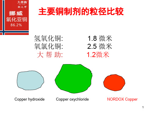
•放大镜下大帮助颗粒形状
x 30
x 80
3
高覆盖率
• 较大的比表面积 =溶解释放快(活性高)Biblioteka 较大的比表面积 =溶解释放快(活性高)
• 药剂分布均匀,形成致密保护层 • 杀灭残存在作物表面的病原物 • 随时杀灭外来的病原物 • 药效发挥充分
4
高覆盖率的意义
微粒越小单位重量的颗粒数量就越多,杀菌活性就越
杂化”,把时间、精力、金钱浪费在自己不该 做的事情上。憨厚、实在、自觉或不自觉按科 学规律办事的人,经常被人们当成傻瓜。
◑ 简单就是先进,效率就是能力。 37
模糊治病的理由:
科学的模糊就是精确。
几十万种真菌、细菌;病原物发生变异;最权威的专家也无法识 别各种病害;
• 病原物无所不在,病害每年都会必然发生; • “状态函数”对防治病害的启示与思考 • 与起始状态和结果有关,与过程或路径无关。 • 农户关心的不是杀菌的过程,要的是能有效预防和控制病害发
本30%以上。
注意:不得随意提高施药浓度
20
性能价格比——优势凸现
• 国际市场(伦敦金属期货市场)铜原料价格 持续上涨4倍以上。
• 硫酸铜由5000元/吨左右上涨,目前: 19000---21000元/吨左右;
• 价格 保持比同类产品低 10——30%。
21
性价比
• 对比全球现有的主要铜制剂,说明可最大 量地提供杀菌活性物。
• 美国为“豁免” • 加拿大为“安全” • 德国为15mg/kg • 荷兰为10mg/kg。
18
安全环保
金属
FAO LiMITS
AGP:CP/251
大帮助
(平均)
砷
75 ppm
铜的氧化物

1氧化亚铜 2氧化铜
氧化亚铜
氧化亚铜为一价铜的氧化物,红色或暗红色结晶性粉末。不溶 于水和醇,溶于盐酸、氯化铵、氨水,微溶于硝酸。溶于盐酸生 成白色氯化亚铜结晶粉末。遇稀硫酸和稀硝酸生成铜盐。在空气 中会迅速变蓝。能溶于浓碱、三氯化铁等溶液中。在湿空气中逐 渐氧化成黑色氧化铜。 在酸性溶液中岐化为二价铜,说明在溶液中,二价铜离子的稳 定性大于一价铜离子,例如氧化亚铜和硫酸反应,生成硫酸铜和 铜。 Cu2O+H2SO4=CuSO4+Cu+H2O 氧化亚铜与氨水和氢卤酸反应,因生成络合物,不岐化成二价 铜和铜 溶于浓氨溶液形成无色配合物 [Cu(NH3)2]+,其在空气中被氧 化为蓝色的 [Cu(NH3)4(H2O)2]2+ 氧化亚铜氧化亚铜可溶于盐酸生成 HCuCl2(氯化亚铜的配合 物),也可溶于硫酸及硝酸分别形成硫酸铜及硝酸铜。
羟基乙酸
国外通常用2%羟基乙酸和1%甲酸酌混合液 作清洗剂,在82—104℃温度下循环流动清 洗,对铁锈和氧化皮有较好的清洗效果。 中国目前不生产羟基乙酸,所以使用较少。
草酸
草酸对金属有一定腐蚀作用,如钢铁在常温 下能被草酸慢慢腐蚀,但在加热情况下会 生成草酸铁保护膜,能阻止腐蚀的进行; 铝、镍、铜、不锈钢等材料对草酸的耐蚀 性较好
氧化铜
氧化铜是一种铜的黑色略显两性氧化物, 稍有吸湿性。熔点1326℃。不溶于水和乙醇, 溶于酸、氯化铵及氰化钾溶液,氨溶液中 缓慢溶解。
健康危害
误服或吸入大量氧化铜粉尘可能引起金属烟 热,出现寒战、体温升高,同时可伴有呼 吸道刺激症状。长期接触,可能引起呼吸 道及眼结膜刺激、鼻衄、鼻粘膜出血点或 溃疡,甚至鼻中隔穿孔以及皮炎
毒性防护
氧化铜与氧化亚铜

用吉布斯函数算一下,你会发现高温时氧化亚铜的稳定性是高于氧化铜的!!因此与氧气的量根本无关。
在任何条件下,只要温度够高就不会有氧化铜。
高温处理铜时,氧气不足而铜过量,导致生成氧化亚铜氧化亚铜稳定!!从结构看,铜原子价电子结构是3d104S1 当铜原子失去一个电子时,最外层变为全充满状态。
说明一价铜稳定!从实验看,在加强热时,黑色氧化铜可分解为红色氧化亚铜和氧气!也说明一价铜稳定!常温条件,CuO比Cu2O稳定;而高温条件下,反之对氧化铜加热能否得到氧化亚铜?可以,但需要高温。
因为高温下氧化亚铜比氧化铜稳定。
加热改待测物,质量有增加,表示有O2与Cu2O反应生成CuO1 氧化铜加热到多少度的时候会变成氧化亚铜?2 1800度的氧化亚铜是沸腾还是失1个氧原子?1 2002 失1个氧原子氧化亚铜有什么性质?不溶于水,溶液显蓝色高温时氧化亚铜的稳定性是高于氧化铜氧化亚铜只能与强氧化性酸反应,他能被进一步被氧化得到+2价的铜.这两种物质都不溶于水,含有+2价铜离子的溶液显蓝色,+1价铜离子在酸性溶液中不稳定氧化铜是不溶于强氧化性酸的,因为他不能再被氧化了(+2价已经是铜的最高价态了)但氧化亚铜是可以和强氧化性酸反应的,他能被进一步被氧化得到+2价的铜.氧化亚铜在热水中迅速水解为红色,生成氧化铜水合物,与强酸缓慢反应,能吸收CO而生成复合物。
氧化亚铜—红色不溶于水的碱性氧化物,在酸性溶液中,发生歧化反应.是" —CHO"和Cu(OH)2反应还原产物最近想做个实验,把氧化铜加热,使他分解。
但不知CuO的分解温度是多少,所以来问一下,以便知道究竟用不用酒精喷灯温度达到100-120℃用什么办法区分微量的纯铜和氧化亚铜?投入AgNO3溶液,氧化亚铜无变化,Cu表面有银白色物质生成。
Cu+2AgNO3=Cu(NO3)2+2Ag氧化亚铜可以和稀酸反应吗?悬赏分:0 - 解决时间:2007-1-27 07:19也就是说,在常温下,能不能用稀酸溶解或者分解氧化亚铜?提问者:calvancouver - 同进士出身六级最佳答案氧化亚铜z只能与强氧化性酸反应,而稀酸不具备强氧化性氧化亚铜能够与稀硝酸反应吗?悬赏分:10 - 解决时间:2007-7-4 12:10反应生成什么?提问者:月影至爱- 魔法学徒一级最佳答案其实就是湿法冶金中Cu2O的浸出反应今天我刚给人上课讲到这个反应3Cu2O + 14HNO3 = 6Cu(NO3)2 + 2NO + 7H2O这个反应是对的但如果是硫酸,则:Cu2O+H2SO4=Cu+CuSO4+H2O只能生成部分的Cu2+离子,本质上是岐化反应回答者:flowchen -助理二级6-21 10:58 提问者对于答案的评价:谢谢啦!评价已经被关闭目前有3 个人评价好100%(3)不好0% (0)其他回答共 5 条硝酸铜和水回答者:爱影娴- 初入江湖二级6-21 10:49 能啊硝酸铜水二氧化氮回答者:qq3588577 - 秀才三级6-21 10:52 能,因为稀硝酸具有较强的氧化性,而氧化亚铜中亚铜离子因为不是最高价态而具有一定的还原性,所以它们之间可以发生氧化还原反应。
氧化亚铜 化学式-概述说明以及解释

氧化亚铜化学式-概述说明以及解释1.引言1.1 概述氧化亚铜是一种重要的无机化合物,化学式为Cu2O。
它具有多种重要的性质和应用,因此引起了广泛的研究兴趣。
氧化亚铜是一种红色固体,具有半导体性质。
它的晶体结构是立方晶系,通常呈现为立方体或正十二面体形状。
这种化合物的熔点相对较低,约为1235摄氏度。
氧化亚铜在化学反应中常被用作重要的催化剂。
它具有催化氧化反应以及电化学反应的能力,因此在电化学工业和环境保护领域有着广泛的应用。
此外,氧化亚铜在太阳能电池、光电催化和传感器等领域也具有潜在的应用价值。
在本文中,我们将重点介绍氧化亚铜的性质和制备方法。
首先,我们将对氧化亚铜的物理性质、化学性质和热性质进行详细的描述。
然后,我们将介绍几种常见的制备方法,包括化学合成法、电化学合成法以及溶液法等。
这些方法在制备高纯度氧化亚铜样品和纳米材料方面都具有重要的意义。
通过本文的介绍,读者将能够全面了解氧化亚铜的特性和制备方法,并进一步认识到它的重要性和潜在应用。
在结论部分,我们还将总结氧化亚铜的重要性,并展望其未来的研究方向,以促进相关领域的科学发展和技术创新。
文章结构是指文章的组织和布局方式,它决定了文章内容的呈现顺序和逻辑关系。
本文将按照如下结构进行展开:1. 引言1.1 概述在这部分,将简要说明氧化亚铜是什么,以及它的重要性和应用领域。
1.2 文章结构此部分将详细介绍本文的组织结构和目录,告诉读者整篇文章将涵盖哪些内容。
1.3 目的这一部分将明确本文的写作目的,即为什么要探讨氧化亚铜的性质和制备方法,以及展望其未来的研究方向和重要性。
2. 正文2.1 氧化亚铜的性质这部分将详细阐述氧化亚铜的物理性质(如颜色、结构等)和化学性质(如化学反应、溶解性等)。
2.2 氧化亚铜的制备方法在这一部分,将介绍不同的制备氧化亚铜的方法,包括化学合成方法、物理合成方法等,并对其优缺点进行分析和评价。
3. 结论3.1 总结氧化亚铜的重要性在这部分,将回顾氧化亚铜的重要性和应用领域,并总结其在相关领域的作用和意义。
刻面氧化亚铜
刻面氧化亚铜
刻面氧化亚铜是一种常见的化学试剂,通常用于电化学和材料科学领域。
它的化学式为Cu2O,由两个铜原子和一个氧原子组成。
刻面氧化亚铜的用途包括电极材料、电池、光催化剂、太阳能电池等。
它具有良好的导电性和光吸收能力,因此在这些领域中广泛应用。
制备刻面氧化亚铜通常采用化学还原法或热分解法。
其中,化学还原法是最常用的方法,通过将铜离子还原成金属铜来合成氧化亚铜。
而热分解法则是将铜盐加热至高温,使其分解生成氧化亚铜。
刻面氧化亚铜是一种重要的化学试剂,其在电化学和材料科学领域的应用前景广阔。
随着科技的不断进步,相信它的应用会越来越广泛。
- 1 -。
氧化亚铜是什么?适用于哪些方面?
氧化亚铜是什么?适用于哪些方面?氧化亚铜,又称为氧化铜(I),化学式为Cu2O,是一种无机化合物。
它的外观为红色至棕色的结晶,具有一定的半导体性质,在光学、电学、化学等多个领域都有广泛的应用。
物理和化学性质氧化亚铜是一种极稳定的化合物,在常温下不易受到空气和水的影响而氧化。
它的晶格结构由四面体和三角柱构成,形成了一种独特的晶体结构。
氧化亚铜是一种半导体材料,其带隙大小为2.0 eV,具有一定的导电性和光电性能。
同时,它也是弱酸性氧化物,能够与酸或碱发生反应。
应用领域光学领域由于氧化亚铜具有良好的半导体性质和光电性能,因此在光学领域有广泛的应用。
它可以用于制备光伏器件、太阳能电池等光电子器件,还可以制备单晶体、薄片和纤维等光学元件。
同时,在光谱分析、荧光分析、荧光显微镜和激光技术等方面也有重要的应用。
电学领域氧化亚铜还可以用于制备多种电子器件,如电容器、场效应晶体管、半导体激光器和扫描电子显微镜等。
它还可以作为电池材料,制备高性能电池,如锂离子电池和太阳能电池等。
此外,氧化亚铜还可以用于制备载流子探针,进行电学性质研究。
化学领域氧化亚铜在化学分析和催化反应中也有重要应用。
它可以作为催化剂,催化合成多种有机化合物,如三苯基胺、苯丙烯和环己烯等。
同时,氧化亚铜还可以用于分离和富集组分,如分离合成氨中的氢气和氮气。
其他领域除了以上应用领域外,氧化亚铜还可以用于制备特殊材料、防蚀材料和防晒材料等。
在医学领域,氧化亚铜也可以用于制备防腐剂和药物载体。
结论综上所述,氧化亚铜是一种具有广泛应用的无机化合物,其优越的半导体性质和光电性能在光学和电学领域有着重要应用。
同时,在化学和医学领域也有诸多应用,有一定的研究和应用前景。
铜及其化合物PPT课件

第8页/共11页
铜的冶炼“三方法”:
(1)湿法炼铜:Fe+CuSO4====FeSO4+Cu。 (2)高温炼铜:工业上用高温冶炼黄铜矿的方法获得铜
(粗铜):
2CuFeS2+4O2 2Cu2S+3O2 2Cu2O+Cu2S
Cu2S+3SO2+2FeO(炉渣) 2Cu2O+2SO2
H2+Cu2O
转化关系
4CuO 2Cu2O+O2↑
2Cu+H2O
第4页/共11页
*黑色氧化铜在高温下分解为红色的Cu2O,化学方程
高温
式为_4_C_u_O__=_=_=_=__2_C_u_2O__+_O_2_↑。 氧化铜与酸反应生成盐和水:CuO+2H+==Cu2++H2O
*红色的Cu2O与稀硫酸反应,溶液变蓝,同时生成红 色的单质铜,离子方程式为_C_u_2_O_+_2_H_+_=_=_=_=_C_u_+_C_u_2_++ H__2O_。
第1页/共11页
⑴与非金属单质
铜绿、孔雀石
与O2:
△ 2Cu+O2=====2CuO
潮湿空气中:2Cu+O2+CO2+H2O===Cu2(OH)2CO3
点燃 + 与Cl2:Cu+Cl2=====C2 uCl2
(棕黄色烟,加水振荡得蓝色溶液)
△ +1 与S:2Cu+S=====Cu2S
(黑色固体)
第2页/共11页
铜硫盐酸能铜杀死某些细菌,并能抑制藻类生长,游泳馆常用 ____________作池水消毒剂;
铜 氧化亚铜

铜氧化亚铜概述铜是一种常见的金属元素,具有良好的导电和导热性能,广泛应用于电子、建筑、制造等领域。
氧化亚铜是铜与氧化物结合而成的化合物,具有多种应用价值。
本文将介绍铜和氧化亚铜的基本性质、制备方法以及主要应用领域。
铜的基本性质物理性质•铜是一种红色金属,具有良好的延展性和韧性。
•密度为8.96 g/cm³,熔点为1083°C。
•铜具有优异的导电和导热性能,是一种重要的电工材料。
化学性质•铜在常温下相对稳定,但容易被空气中的氧气氧化形成黑色氧化物。
•可以与非金属元素如硫、卤素等反应生成相应的化合物。
氧化亚铜的制备方法热分解法将碳酸铜(CuCO₃)加热至高温(约900°C),发生分解反应生成氧化亚铜(Cu₂O)和二氧化碳(CO₂)。
CuCO₃ → Cu₂O + CO₂化学还原法将铜离子溶液与还原剂反应,使铜离子被还原成氧化亚铜颗粒沉淀。
电化学法利用电解池的原理,在电解质溶液中通过电流作用下,将阳极上的铜溶解成铜离子,然后在阴极上沉积出氧化亚铜。
氧化亚铜的应用领域电子材料由于氧化亚铜具有良好的导电性能和光学特性,可以应用于太阳能电池、光伏材料等领域。
此外,氧化亚铜也可以作为半导体材料用于制备晶体管、二极管等器件。
催化剂氧化亚铜具有良好的催化活性,在有机合成反应中常被用作催化剂。
例如,氧化亚铜可以催化苯环上的芳烃与醇发生部分氢解反应。
防腐剂由于氧化亚铜具有较强的抗菌性能,可以应用于木材、涂料等防腐领域。
氧化亚铜可以抑制微生物的生长,延长产品的使用寿命。
纳米材料氧化亚铜纳米颗粒具有较大的比表面积和特殊的光学、电学性质,被广泛应用于催化、传感器、电子器件等领域。
纳米级氧化亚铜具有更高的催化活性和选择性,可提高反应效率。
结论铜和氧化亚铜作为重要的材料,在多个领域中发挥着重要作用。
铜具有良好的导电和导热性能,广泛应用于电子设备制造;而氧化亚铜则具有多种应用价值,包括电子材料、催化剂、防腐剂和纳米材料等。
- 1、下载文档前请自行甄别文档内容的完整性,平台不提供额外的编辑、内容补充、找答案等附加服务。
- 2、"仅部分预览"的文档,不可在线预览部分如存在完整性等问题,可反馈申请退款(可完整预览的文档不适用该条件!)。
- 3、如文档侵犯您的权益,请联系客服反馈,我们会尽快为您处理(人工客服工作时间:9:00-18:30)。
缺点: 1: 硫酸清洗金属,容易发生氢脆,所谓氢 脆是酸与金属反应产生的氢气被金属吸收 后引起金属发脆、性质变坏的现象 2: Cu2O+H2SO4=CuSO4+Cu+H2O 使用硫酸是不是使得网穴内含有铜杂质
8
盐酸处理
铜:只会在氧化条件下被盐酸腐蚀 使用盐酸作清洗液时:一般使用%以下浓度并在 常温下使用,尽量避免升温使用以防产生酸雾 由于大多数氯化物都是易溶于水的,铁锈、铜锈、 铝锈都可以很好地溶解在盐酸中。盐酸价格便宜 所以被广泛用于上述污垢的清洗中。盐酸清洗液 适用于碳钢、黄铜、紫铜及其他铜合金材料的设 备清洗。
17
草酸
草酸对金属有一定腐蚀作用,如钢铁在常温 下能被草酸慢慢腐蚀,但在加热情况下会 生成草酸铁保护膜,能阻止腐蚀的进行; 铝、镍、铜、不锈钢等材料对草酸的耐蚀 性较好
18
1
毒性防护
本品粉尘在空气中含量达到0.22~ 14mg/m3时,工作1~2h后会引起急性中毒, 表现为头痛、无力、咽和结膜发红、恶心、 肌肉痛、有时呕吐和腹泻、疲乏、体温升高。 一天以后体温可恢复正常,但仍无力,头痛, 眩晕,脉数加快,淋巴细胞增多。
空气中最高容许浓度为0.1mg/m3。 可戴 口罩、防尘眼镜,穿防护工作服,工作后要 洗淋浴。
11
铜:由于被硝酸氧化生成氧化铜,所以可 被所有浓度的硝酸溶解。 工业上用于酸洗的硝酸浓度一般在5%左右, 在浓度较低时隋况下,硝酸比较稳定,不 易分解,氧化性减弱,主要发挥酸性的作 用
12
硝酸清洗铜锈效果比较好,所以在清洗不锈钢 以及铜设备时常用硝酸。在工业上硝酸主要用 于清洗不锈钢、碳钢、黄铜、铜及碳钢-不锈钢 设备以及黄铜-碳钢焊接的组合体设备。去除氧 化铁皮、铁垢的速度快、时间短,并且对碳钢、 不锈钢、铜的腐蚀性较低。 由于硝酸在低浓度下对大多数金属均有强烈腐 蚀作用,因此用硝酸作酸洗剂时,为防止其对 金属的腐蚀也要加入缓蚀剂。
2
氧化铜
氧化铜是一种铜的黑色略显两性氧化物, 稍有吸湿性。熔点1326℃。不溶于水和乙醇, 溶于酸、氯化铵及氰化钾溶液,氨溶液中 缓慢溶解。
3
健康危害
误服或吸入大量氧化铜粉尘可能引起金属烟 热,出现寒战、体温升高,同时可伴有呼 吸道刺激症状。长期接触,可能引起呼吸 道及眼结膜刺激、鼻衄、鼻粘膜出血点或 溃疡,甚至ቤተ መጻሕፍቲ ባይዱ中隔穿孔以及皮炎
酸清洗处理
6
硫酸处理
铜由于金属活动性差,不能从酸中置换出氢 离子,所以一般情况下不会被硫酸溶解, 只有在浓硫酸加热条件下,铜被氧化才能 被硫酸溶解 。 硫酸又是一种不易挥发的强酸,所以可以通 过适当加热来加快清洗速度,一般用5%~ 15%浓度的硫酸作清洗液时,可以加热到 50~60℃以加快清洗速度
4
防护措施
密闭操作,局部排风。 呼吸系统防护: 空气中粉尘浓度超标时, 必须佩戴自吸过滤式防尘口罩。紧急事态 抢救或撤离时,应该佩戴空气呼吸器。 眼睛防护: 戴化学安全防护眼镜。 身体防护: 穿防毒物渗透工作服。 手防护: 戴橡胶手套。 其他防护: 及时换洗工作服。注意个人清洁 卫生。
5
1 硫酸 2盐酸 3 硝酸
13
有机酸清洗
氨基磺酸 羟基乙酸 草酸
14
氨基磺酸
氨基磺酸的水溶液酸性与盐酸、硫酸相似, 因此又称固体硫酸。它具有不挥发,无臭 味,对人毒性极小的特点。但长时间与皮 肤接触,或进入眼睛也是有害的,应注意 避免。但当相对湿度大于70%时,氨基磺酸 开始潮解,在高温下会水解生成硫酸铵和 硫酸氢铵
15
Cu2O+H2SO4=CuSO4+Cu+H2O 氧化亚铜与氨水和氢卤酸反应,因生成络合物,不岐化成二价 铜和铜
溶于浓氨溶液形成无色配合物 [Cu(NH3)2]+,其在空气中被氧 化为蓝色的 [Cu(NH3)4(H2O)2]2+
氧化亚铜氧化亚铜可溶于盐酸生成 HCuCl2(氯化亚铜的配合 物),也可溶于硫酸及硝酸分别形成硫酸铜及硝酸铜。
氨基磺酸水溶液对铁锈作用较慢,可添加一 些氯化物如NaCl等,使之缓慢产生盐酸, 从而朋效地溶解铁锈 由于氨基磺酸盐的多数金属盐在水中溶解度 较高,不会在清洗液中产生沉淀。而氨硼 酸对金属腐蚀性小,所以常被用来清洗钢 铁、铜、不锈钢、铝以及陶瓷等材料制造 的设备表面上的铁锈和水垢
16
羟基乙酸
国外通常用2%羟基乙酸和1%甲酸酌混合液 作清洗剂,在82—104℃温度下循环流动清 洗,对铁锈和氧化皮有较好的清洗效果。 中国目前不生产羟基乙酸,所以使用较少。
氧化亚铜
氧化亚铜为一价铜的氧化物,红色或暗红色结晶性粉末。不溶 于水和醇,溶于盐酸、氯化铵、氨水,微溶于硝酸。溶于盐酸生 成白色氯化亚铜结晶粉末。遇稀硫酸和稀硝酸生成铜盐。在空气 中会迅速变蓝。能溶于浓碱、三氯化铁等溶液中。在湿空气中逐 渐氧化成黑色氧化铜。
在酸性溶液中岐化为二价铜,说明在溶液中,二价铜离子的稳 定性大于一价铜离子,例如氧化亚铜和硫酸反应,生成硫酸铜和 铜。
9
由于盐酸对钢铁等不少金属材料有强烈的腐蚀 作用,因此在清洗中为保证设备不被腐蚀,在 盐酸中要添加缓蚀剂。
10
硝酸
硝酸分解时产生的初生态原子氧,有很强的 氧化性,这是硝酸的重要特性,因此硝酸 对贵金属(如金、铂)之外的许多其他金属都 有广泛的溶解能力。 但应注意的是硝酸分解产生的棕红色二氧 化氮气体有很强的毒性,使用时应十分注 意安全,要在通风良好的环境中进行操作。
