Unclassified TN-2006-00539 Title 24 GHz Antenna Array Design with Suppressed Sidelobes
低功耗限制的级间匹配型2.45GHz低噪声放大器设计

以下 ) . 线 性 度 ;4良好 的反 向 隔离 特 性 。而 其 噪 声 特 性 决 定 了整 个 系统 的噪 声 性 能 。传 统 的低 ;3良好 . 噪 声 放 大 器 的 设计 步 骤 …有 两 个 缺 陷 : ~ 、 噪 声 系 数 表 达 式 中没 有 包 含 共 栅 管 的 噪 声 ,在频 率 升 高 的
第l 3卷 第 6期 20 0 8年 1 2月
文 章编 号 : 10 .29(0 8 0 —0 30 0 704 2 0 ) 60 7 -5
电路 与 系 统 学 报
J 0URNAL OF CI RCUI TS AND YS M S S TE
VO11 .3
No. 6
De e e , 2 o c mb r o 8
度 不 恶 化 ,又 可 以 同 时满 足 噪 声和 功 率 匹 配 的方 法 一在 输 入 管 的栅 源 极 之 间 附 加 一 个 电容 改进 前后 电路 的噪 声 、增 益 和 线 性 度进 行 比较 ,从 而 证 明 了 分 析 的 正确 性 。 ,并 对
2 传 统 L A 的 设 计 方 法 N
gd 1 O
; 为
乙 l十 ( ̄ dl -g
( 捌 是 共源 管 M g 在零 偏 条 件 下 的漏 极 电导 , 是 M g 的跨 导 ) ;
是 输 入 匹 配 回路 的 品质 因子 ; R 是栅 电感 的 寄 生 电 阻 ; ,
是 栅 极 电 阻 ;并 在 此 基 础 上 提 出 了功 耗
提 出 一种 改 进 噪 声 性 能 的方 法一 级 间匹 配 , 并 比较 了匹 配 前 后 电路 的噪 声 性 能 ,给 出 了 S e t 的仿 p cr e
真 结 果 。又 在 低 功 耗 的约 束 条 件 下 ,通 过对 噪 声 匹 配 和 功 率 匹 配条 件 的讨 论 ,提 出 了一 种 既保 证 线 性
多通道低相噪同步频率源设计

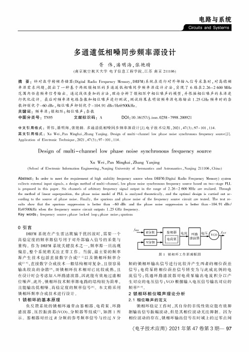
电路与系统多通道低相噪同步频率源设计胥伟,潘明海,张艳睛(南京航空航天大学电子信息工程学院,江苏南京211106)摘要:针对数字射频存储器(Digital Radio Frequency Memory,DRFM)系统在进行对外部输入信号采集时,对高稳频率源需求问题,提出了一种基于两级锁相环的多通道低相噪同步频率源设计方法,实现了6路在2.26〜2600MHz 范围内任意频率信号输出遥通过线性叠加的方法,理论分析了锁相环中相位噪声的模型,并根据相位噪声的来源进行优化设计遥最后对频率源电路杂散和相位噪声进行测试,测试结果表明该频率源电路输出1.25GHz频率时的杂散抑制优于-60dBc,相位噪声抑制优于-104.91dBc/Hz@500kHz遥关键词:频率源;锁相环;相位噪声;杂散中图分类号:TN95文献标识码:A DOI:10.16157/j.issn.0258-7998.200921中文引用格式:胥伟,潘明海,张艳睛.多通道低相噪同步频率源设计[J].电子技术应用,2021,47(3):97-101,114.英文引用格式:Xu Wei,Pan Minghai,Zhang Yanjing.Design of multi-channel low phase noise synchronous frequency source[J]. Application of Electronic Technique,2021,47(3):97-101,114.Design of multi-channel low phase noise synchronous frequency sourceXu Wei,Pan Minghai,Zhang Yanjing(School of Electronic Information Engineering,Nanjing University of Aeronautics and Astronautics,Nanjing211106,China) Abstract:In order to meet the requirement of high stability frequency source when DRFM(Digital Radio Frequency Memory)systemcollects external input signals,a design method of multi-channel,low phase noise synchronous frequency source based on two-stage PLL is proposed in this paper.Six channels of arbitrary frequency signal output in the range of2.26〜2600MHz are realized.Through the method of linear superposition,the phase noise model of PLL is analyzed theoretically,and the optimal design is carried out according to the source of phase noise.Finally,the spurious and phase noise of the frequency source circuit are tested.The test results show that the spurious suppression is better than-60dBc and the phase noise suppression is better than-104.91dBc/ Hz@500kHz when the frequency source circuit outputs 1.25GHz frequency.Key words:frequency source;phase locked loop;phase noise;spurious0引言DRFM系统在产生雷达欺骗干扰回波时,需要一个高稳定度的频率源信号用于对外部输入信号的采集与重构。
电磁信号调制识别中的对抗性攻击技

doi:10.3969/j.issn.1003-3114.2022.06.019引用格式:王满喜ꎬ史明佳ꎬ陆科宇ꎬ等.电磁信号调制识别中的对抗性攻击技术研究[J].无线电通信技术ꎬ2022ꎬ48(6):1098-1104.[WANGManxiꎬSHIMingjiaꎬLUKeyuꎬetal.ResearchonAdversarialAttacksTechnologyinModulationRecognition[J].RadioCom ̄municationsTechnologyꎬ2022ꎬ48(6):1098-1104.]电磁信号调制识别中的对抗性攻击技术研究王满喜1ꎬ史明佳2ꎬ陆科宇1ꎬ张思成2∗(1.电子信息系统复杂电磁环境效应国家重点实验室ꎬ河南洛阳471003ꎻ2.哈尔滨工程大学信息与通信工程学院ꎬ黑龙江哈尔滨150001)摘㊀要:无线通信常需要检测通信信号的调制类型ꎬ来分析估计调制参数ꎬ或发出干扰信号破坏对方通信系统ꎮ深度学习成为研究热点为调制信号识别带来了极大的便利ꎬ然而人工智能模型面临着来自对抗样本严重的威胁ꎬ这大大降低了深度机器学习任务执行的高可靠性度和安全性ꎮ针对电磁信号识别中的对抗攻击问题ꎬ使用Matlab生成数据集ꎬ并设计深度神经网络为问题研究的基础ꎮ进一步对对抗样本进行分析ꎬ结合信号理论ꎬ给出了通信信号对抗样本产生原因的分析ꎬ并研究经典的基于梯度生成的对抗样本生成算法ꎬ实现在不同攻击类型及迭代步长下的白盒攻击ꎬ可将原始模型识别率降低30%以上ꎮ仿真实验证明ꎬ卷积神经网络极易受到对抗攻击ꎬ对抗样本会对智能模型的辨识精度产生影响ꎬ对于深度学习模型的安全性与可靠性的研究具有重要价值ꎮ关键词:调制识别ꎻ深度学习ꎻ对抗攻击ꎻ机理解释中图分类号:TN929.5㊀㊀㊀文献标志码:A㊀㊀㊀开放科学(资源服务)标识码(OSID):文章编号:1003-3114(2022)06-1098-07ResearchonAdversarialAttacksTechnologyinModulationRecognitionWANGManxi1ꎬSHIMingjia2ꎬLUKeyu1ꎬZHANGSicheng2∗(1.StatekeyLaboratoryofComplexElectromagneticEnvironmentalEffectsofElectronicInformationSystemsꎬLuoyang471003ꎬChinaꎻ2.CollegeofInformationandCommunicationEngineeringꎬHarbinEngineeringUniversityꎬHarbin150001ꎬChina)Abstract:Wirelesscommunicationoftenneedstodetectthemodulationtypeofcommunicationsignalstoanalyzeandestimatemodulationparametersꎬortosendinterferencesignalstodestroyadversarycommunicationsystems.Deeplearninghasbecomearesearchhotspotꎬwhichbringsgreatconvenienceformodulationsignalrecognition.Howeverꎬartificialintelligencemodelsarefacedwithaseriousthreatfromcounteringsamplesꎬwhichgreatlyreducesthehighreliabilityandsecurityofdeepmachinelearningtasks.AimingattheproblemofcounterattackinelectromagneticsignalrecognitionꎬMatlabisusedtogeneratedatasetsꎬandadeepneuralnetworkisdesignedasthebasisofproblemresearch.Furthermoreꎬcountermeasuresamplesareanalyzed.Basedonsignaltheoriesꎬthecausesofcommunicationsignalcountermeasuresamplesareanalyzedꎬandaclassicalcountermeasuresamplegenerationalgorithmbasedongradi ̄entgenerationisstudied.White ̄boxattackunderdifferentattacktypesanditerativestepscanreducetherecognitionrateoftheoriginalmodelbymorethan30%.Experimentalresultsshowthatconvolutionneuralnetworkisveryvulnerabletocounterattackꎬandcounteringsampleswillaffecttheidentificationaccuracyoftheintelligentmodelꎬwhichisofgreatvalueforresearchonthesecurityandreliabilityofthedeeplearningmodel.Keywords:modulationrecognitionꎻdeeplearningꎻcounterattackꎻmechanismexplanation收稿日期:2022-08-19基金项目:中央高校基本科研业务费基金资助项目(3072022CF0804ꎬ3072022CF0601)FoundationItem:FundamentalResearchFundsfortheCentralUniversities(3072022CF0804ꎬ3072022CF0601)0㊀引言自动信号调制分类(AutomaticModulationCla ̄ssificationꎬAMC)是无线通信系统中的重要组成部分ꎬ通常用于信号检测和解调技术ꎬ在数据传输等应用中发挥着重要作用ꎮ基于传统方法识别调制信号方法识别不仅需要专业知识ꎬ工作量大ꎬ人工成本高ꎬ还容易造成误判[1]ꎮ近年来ꎬ随着深度学习的普及ꎬ人工智能技术在电磁空间问题中的突出表现得到了业界的认可ꎮ研究人员针对调制信号数据集设计深度学习网络ꎬ获得了明显优于传统网络的性能[2-3]ꎬ至此ꎬ更多的方法被投入研究如何提升识别准确率并适应于各种场景(小样本[4]㊁迁移学习[5]㊁模型压缩[6]㊁轻量化部署[7]等)ꎮ然而ꎬ对抗样本的出现对基于深度神经网络的调制识别任务提出了新的挑战ꎮ恶意生成的微小扰动ꎬ在人眼不可分辨的情况下可愚弄模型ꎬ使输入信号的调制类型预测改变ꎮ近年来ꎬ对抗样本在电磁领域的研究已经取得一定发展ꎮ2018年ꎬSadeghi发现对抗样本能降低信号识别性能ꎬ这是电磁领域首次发现对抗样本[8]ꎮTu等人将生成性对抗网络扩展到半监督学习ꎬ表明它是一种可以用来创建数据效率更高的分类器的方法[9]ꎮ2020年ꎬZhao等人对信号识别过程中的对抗攻击进行检验ꎬ降低了模型的正确性ꎬ并验证了该模型的泛化能力[10]ꎮFlowers将真实物理场景下的通信信号中引入对抗样本ꎬ根据不同的攻击位置展开研究ꎬ并提出将误码率作为评估指标[11]ꎮ2021年ꎬLin等人分析了几种基于梯度的对抗攻击方法对调制识别的影响ꎬ结果表明ꎬ当扰动强度为0.001时ꎬ该方法的预测精度将降低50%[12]ꎮTu等人创建了一个大规模的真实无线电信号数据集ꎬ使用新的数据集对深度学习模型的性能进行了深入的研究[13]ꎮBao等人考察了非目标攻击和目标攻击对基于卷积神经网络设备识别的影响ꎬ并提出了Logits的组合评估指标ꎬ以丰富评估标准[14]ꎮZhang等人设计了一种结合快速推理和反白盒梯度攻击的调制分类防御模型BMCDN来检测物联网中的恶意攻击和干扰ꎬ在保证模型分类性能的同时获得防御性能[15]ꎮ目前针对调制识别的对抗攻击主要集中在提高攻击性能上[16-17]ꎬ通信领域的研究仍处于初步阶段ꎬ对抗样本缺乏理论解释研究ꎬ现有解释大多是局限在假设解释ꎬ没有充分结合通信信号的特性ꎬ仍存在很多理论空白ꎻ对抗攻击性能不强ꎬ仍需继续研究提升攻击有效性ꎮ对电磁信号对抗机理进行解释ꎬ有助于给研究人员提供可靠的理论依据ꎬ进一步改进对抗样本系统的知识ꎬ为提高攻击效果和模型的安全性ꎬ以及评估对信号识别模型的影响有很大的帮助ꎮ本研究结合电磁信号的物理特性进行机理解释等基础研究ꎬ从攻击者的角度出发ꎬ设计的精细扰动加入到输入信号中ꎬ以探讨基于深度神经网络调制识别的对抗攻击性能ꎬ量化对调制波形的扰动程度ꎮ1㊀神经网络研究基础1.1㊀多层感知机多层感知机是由感知器学习算法(PerceptronLearningAlgorithmꎬPLA)提出的ꎬ为较大神经网络的前身ꎮ多层感知机的超参数需要进行调整ꎬ必须使用交叉验证技术来找到这些参数的理想值ꎮ权重调整训练通过反向传播完成ꎮ神经网络越深ꎬ处理数据的能力越强ꎬ然而更深的层可能会导致渐变问题消失ꎬ需要特殊的算法来解决这个问题ꎮ基于单元操作的非线性函数来对隐藏变量进行变换ꎬ并使其转换为下一层的完全连通ꎬ这种功能叫做激活函数ꎮH=ϕ(XWh+bh)ꎬ(1)O=HWo+bꎬ(2)式中ꎬϕ表示激活函数ꎮ图1显示了常见的非线性激活函数ꎮ图1㊀常用的激活函数Fig.1㊀Commonlyusedactivationfunctionssigmoid函数是最早期且最常用的一个ꎬ对于一个定义域在R内的输入ꎬsigmoid将输入变换为区间0~1的输出ꎬ公式为:sigmoid(x)=11+e-xꎮ(3)tanh函数将定义在R的输入变换为一个固定区间的函数ꎮ不同的是ꎬtanh将输入区间变换到-1~1ꎮ公式为:tanh(x)=1-e-2x1+e-2xꎮ(4)近来修正线性单元(RectifiedlinearunitꎬReLU)因实现简单ꎬ同时在各种预测任务中表现良好受到关注ꎮReLU公式为:ReLU(x)=max(xꎬ0)ꎮ(5)1.2㊀卷积神经网络卷积神经网络(ConvolutionalNeuralNetworksꎬCNN)本质是一种多层次的感知机器ꎬ其特征主要有两种:一是局部链接ꎻ二是权重分享ꎬ降低了模型的复杂性ꎬ即过度拟合的危险ꎮ其中ꎬ卷积层㊁池化层㊁全连接层是组成卷积神经网络的部分ꎮ卷积层一般由多个卷积核以及对应的卷积函数组成ꎬ卷积核是检测提取特征的作用ꎬ其中二维卷积操作可表示为:rl(iꎬj)=ða-1p=0ðb-1q-0Wfa-pꎬb-qrl-1(1+s(i-1)-pꎬ1+s(j-1)-q)ꎮ(6)池化的主要思想是下采样ꎬ以降低更多层的复杂性:rl=βdown(rl-1)+blꎮ(7)全连接层通常如下所示:rl=σ(Wlrl-1+bl)ꎬ(8)式中ꎬWlɪRNlˑNl-1ꎬblɪRNl代表第l层网络的参数ꎬσ( )代表激活函数ꎮ2㊀对抗样本Szegdy等人首先提出了对抗样本的概念ꎬ该研究发现了神经网络的两种 非常规 现象ꎬ其中之一是神经网络在图像分类中的脆弱性[18]ꎮ针对对抗样本问题进行建模ꎬ提出了以下优化问题:Minimizer2subjecttof(x+r)=lꎬx+rɪ[0ꎬ1]mꎬ(9)式中ꎬx+r是一个由干净样本x和扰动r组成的对抗样本ꎬl是x的真实标签ꎮf表示分类模型f( )ꎬ是将输入图像映射到标签输出的映射函数ꎮ2.1㊀对抗样本产生原因由于深度学习模型的不可解释性和复杂的数据流形几何结构ꎬ对抗样本产生机理的认识尚没有得到一致的解释ꎬ国内外学者对对抗样本产生机制的研究假设存在着不同的侧重ꎬ并且缺少数理上统一的理论解释ꎬ总的来说ꎬ对于对抗样本产生原因有几种分析[19-20]ꎮ2.1.1㊀流形中的低概率区域解释流形中的低概率区域解释是认为由于对抗样本是总样本概率空间中的某一部分空间ꎬ而训练学习只能学习到有限的子区域ꎬ对抗样本是在训练样本有限的情况下ꎬ超出学习子集的那部分样本ꎬ所以这种情况下ꎬ尤其是需要通过目标函数对模型的向量求取梯度得到最优模型时ꎬ深度神经网络在对抗样本的攻击下就会出现漏洞ꎮ2.1.2㊀对抗样本的线性解释首先说明了一个具有对抗样本的线性模型的存在ꎮ在很多问题中ꎬ单一的输入特性的准确率很低ꎬ当干扰因子的各要素都低于该特征的准确度时ꎬ该分类器对于输入x的反应与对抗样本的反应是不合理的ꎮ考虑权重向量w和对抗样本x~之间的点积:wTx~=wTx+wTηꎮ(10)在高维问题中ꎬ可对输入添加极小的改变ꎬ进而对输出实现大改变ꎮ在此情形中ꎬ即使有多个振幅较大的信号ꎬ线性模型也会被迫仅注意到与其加权值最近的信号ꎮ2.2㊀对抗攻击2.2.1㊀对抗攻击技术对抗样本的研究对于深度学习模型安全性至关重要ꎬ目前常用的攻击包括FGSM㊁PGD㊁MIM㊁BIM㊁DeepFool㊁Carlini和Wagner攻击㊁基于雅可比的显著图方法㊁动量迭代攻击和不同输入迭代攻击等ꎮ(1)快速梯度标志攻击(FastGradientSignMethodꎬFGSM)该方法计算简单ꎬ方便快速生成对抗样本ꎮ在原始信号中加入了人类视觉不能辨识的干扰ꎬ但会造成辨识模型的错误判断ꎮFGSM微扰给出如下:设x~为对抗样本ꎬx为原样本ꎬr为产生的扰动ꎬε是最大扰动ꎬJ为损失函数ꎬ识别出的标签为:㊀㊀㊀㊀㊀rɕ<εꎬ(11)x~=x+rꎬ(12)r=ε sign(∇xJθ(xꎬl))ꎮ(13) (2)基本迭代攻击(BasicIterativeMethodꎬBIM)将FGSM的单步计算转化为多个小步迭代攻击ꎬ并调整摄动方向使之与损失函数梯度的变化方向一致或相反ꎮxᶄi+1=Clipxᶄi+α sign(∇2x(xᶄiꎬy)){}ꎬfori=0tonꎬxᶄ0=xꎬ(14)式中ꎬClipxꎬεz{}表示将z裁剪到[x-εꎬx+ε]的范围ꎬ用来约束坐标的每个输入特征ꎬn为迭代总数量ꎬα为步长ꎮ与单步攻击法相比ꎬ迭代攻击可构建出更加精细的扰动ꎬ并且可以实现更好的攻击效果ꎬ不过计算量随之增加ꎮ(3)梯度投影法(ProjectGradientDescentꎬPGD)PGD攻击是以均匀随机噪声(随机扰动)作为初始化的BIM的变体ꎮ首先在原始样本的容许范围(球状噪声区)中进行随机初始化ꎬ再经过反复迭代生成对抗样本ꎮxᶄt+1=Projxᶄt+α sign(∇xJ(θꎬxᶄtꎬy)){}ꎮ(15)(4)动量迭代法(MomentumIterativeMethodꎬMIM)MIM算法是在迭代时ꎬ通过累积速度向量ꎬ使梯度的衰减加快ꎮ引入动量能使扰动的修正方向得到稳定ꎬ从而避免陷入局部最大值ꎬ可以提高采样的可移动性ꎬ进而提高攻击的成功率ꎮgn+1=μgn+∇xJθ(xᶄnꎬy)∇xJθ(xᶄnꎬy)1ꎬ(16)xᶄn+1=xᶄn+ε sign(gn+1)ꎮ(17)2.2.2㊀对抗攻击技术分类根据攻击者的攻击目的ꎬ攻击方式有两种:目标攻击和非目标攻击ꎮ非目标攻击模型的输出是除真是类别之外的任何类别ꎬ而不指定具体的分类ꎬ一般通过减少初始别类的置信度来实现ꎮ非目标攻击模型的输出是除真实类别之外的任何类别ꎬ而不指定具体的分类ꎮargmaxxᶄJ(f(θꎬxᶄ)ꎬy)ꎬ(18)式中ꎬf为选定的网络模型ꎬL为损失函数ꎮ有针对性的目标攻击模型不仅输出错误ꎬ而且输出是攻击者指定的类别ꎮ有针对性的攻击比非有针对性的攻击更难实现ꎮ其中yt是攻击者想要模型输出的预测类别ꎮargminxᶄJ(f(θꎬxᶄ)ꎬyt)ꎮ(19)根据攻击方对目标模型的知识了解程度可分为白盒攻击㊁灰盒攻击㊁黑盒攻击ꎮ其中ꎬ最常用的就是白盒攻击ꎬ即攻击者能够获得攻击的内部结构㊁权重参数以及训练算法ꎮ而黑盒子的进攻则相反ꎮ按照攻击的多样性可以将攻击方法划分为基于梯度的攻击㊁基于动量的攻击以及基于优化攻击的攻击ꎮ图2显示了常见的对抗样本分类ꎮ图2㊀生成方法的分类Fig.2㊀Classificationofgenerationmethods3㊀电磁信号调制识别中的对抗攻击本节进行对抗攻击实验来验证算法的脆弱性ꎬ并使用对抗训练技术提升模型的鲁棒性ꎮ首先使用正常的样本数据训练网络分类器ꎬ进行对抗攻击实验ꎮ3.1㊀数据集本文使用基于时域波形的I/Q信号识别ꎬ调制方案的数据集由Matlab生成ꎬ该数据集由对应于10种不同调制类型的接收信号复数样本组成ꎬ调制类型包括2ASK㊁2PSK㊁2FSK㊁4ASK㊁4PSKꎬ4FSK㊁8ASK㊁8PSK㊁8FSK㊁16QAMꎬ每个示例具有128个采样点ꎬ用于信号的同相和正交(I/Q)分量ꎬ表示为(2ˑ128)的张量ꎮ按照8ʒ1ʒ1的比例ꎬ把数据集分为训练集㊁测试集和验证集ꎮ3.2㊀网络模型在识别型架构的选择与构建上ꎬ本文选用了VT ̄CNN2作为识别模型ꎬ对该网络的网络参数进行了修正ꎬ使其适用于(2ˑ128)的信号张量ꎮVT ̄CNN2模型的流程如图3所示ꎮ图3㊀VT ̄CNN2模型的流程Fig.3㊀FlowchartoftheVT ̄CNN2model3.3㊀对抗攻击性能对比在开展对抗攻击之前ꎬ首先训练基础模型ꎬ对基础模型进行攻击ꎬ对抗攻击方法包括FGSM㊁PGD㊁BIM㊁MIMꎮ参数包括迭代步长ꎬ实验在NVIDIAGeForceGTX1080Ti上用GPU进行ꎬ且攻击方法是基于深度学习框架Keras和Tensorflow以及对抗样本算法库CleverHans来实现ꎮ通过对不同的参量环境ꎬ研究了在白盒模式下ꎬ对网络进行攻击ꎮ通过对研究过程进行分析ꎬ神经网络的线性可能是其容易被通信信号对抗样本所欺骗的直接原因ꎮ针对线性解释的理论ꎬ选取如前文所述的VT ̄CNN2作为分类器ꎬ基于线性假设理论ꎬ采用梯度攻击算法生成对抗样本ꎮ图4展示了在不同扰动系数情况下的攻击效果ꎬ分析可知ꎬ在没有施加攻击㊁信噪比为0dB的情况下ꎬ模型分类准确度在0.826左右ꎮ扰动水平增加ꎬ模型准确性先迅速下降ꎬ随后减弱并最后稳定下来ꎬ最终识别准确率都接近于0.1ꎬ这说明分类器对扰动是很敏感ꎬ且当扰动大小为0.0010时ꎬ识别精度与攻击前相比降低30%ꎮ图4㊀攻击效果图Fig.4㊀Attackeffectmap并且如前文所述ꎬ对抗扰动导致激活按wTη增长ꎬ可以通过指定η=sign(w)来最大化这种增长ꎬ但要满足最大范数约束ꎮ如果w具有n个维度ꎬ并且权向量的一个元素的平均大小是mꎬ则激活将增长εmnꎬ即表明对于维度比较高的数据ꎬ即使是变化很小的输入信号ꎬ最后也会输出一个很大的变化ꎮ而要输入的通信信号ꎬ具有很多维度的性质ꎬ比如幅度㊁频率㊁相位等ꎬ在不同的传输过程和环境中ꎬ存在着各种噪声及其他因素的影响ꎬ这些影响会对各种维度产生很多扰动ꎬ再加上训练数据有限等原因ꎬ会存在一些样本落入低概率区域ꎬ同时线性空间的微小扰动最终也会在高维空间进行放大ꎬ如图5所示ꎮ经实验验证ꎬ基于线性解释的对抗攻击算法ꎬ可以使得原始模型的识别率大幅下降ꎬ从而证明了基于线性解释的对抗样本生成的可行性ꎮ图5㊀线性解释Fig.5㊀Linearinterpertationofattackeffectmap为研究在不同SNR下攻击效果ꎬ在信噪比为10dB与-10dB下进行实验ꎬ如图6和图7所示ꎮ图6㊀10dB攻击效果图Fig.6㊀Effectpictureof10dBattack图7㊀-10dB攻击效果图Fig.7㊀Effectpictureof-10dBattack比较发现低信噪比时ꎬ原网络识别精度显著降低ꎬ加入攻击的识别精度降低得也更快ꎮ通过对系统信噪比的分析ꎬ在较低的信噪比情况下ꎬ其噪声的功率要远远高于信号的功率ꎬ各种干扰导致信号波形畸变ꎮ相反ꎬ在高信噪比条件下ꎬ模型具有较高的可信度ꎬ识别准确率高ꎬ不易干扰ꎬ因此ꎬ若与低信噪下达到同样程度的攻击率ꎬ需要的扰动更大ꎮ综上分析ꎬ不同的方法对噪声的敏感性程度是不同的ꎬ因此应根据实际情况选择适当的攻击模型ꎻ且信噪比是个影响很大的要素ꎬ对抗样本在不同的信噪比情况下的攻击效果值得继续研究ꎮ为了定量地评估不同方法和模型的攻击效果ꎬ对扰动大小为0.0005和0.0010时的11个SNR下识别效果进行了量化平均处理ꎬ分别计算了4种攻击方法的平均分类精度ꎬ平均分类精度结果如图8所示ꎮ图8㊀平均分类精度图Fig.8㊀Averageclassificationaccuracymap由图8可知ꎬ在4种攻击方法中ꎬPGD㊁BIM和MIM这3种迭代攻击ꎬ其攻击效果皆强于单步攻击法ꎻ从平均效果来看ꎬ攻击效果在不同攻击系数下略有波动ꎬ但MIM仍然是三者中最有效的迭代攻击模型ꎮ且在低扰动的情况下ꎬ单步迭代攻击FGSM的性能与其余4种迭代算法的效果近似ꎬ不同算法的攻击优势没有体现出来ꎮ4 结束语电磁信号识别任务中ꎬ深度学习表现出很强的优越性ꎬ但是很容易被对抗样本所干扰ꎬ这是深度学习模型实际部署应用的最大障碍ꎮ电磁对抗样本存在研究时间短㊁解释机理不明㊁对抗攻击研究仍有较大发展空间等问题ꎬ故本文针对通信领域的对抗样本研究存在着大量的空白的问题ꎬ就电磁信号领域的对抗攻击技术进行了分析ꎬ实现了自动调制信号分类ꎬ所设计的深度学习模型对调制信号数据集可在0dB时达到80%以上的识别准确率ꎻ对于通信信号对抗样本生成机理不明的现状ꎬ结合通信信号特性分析ꎬ对其进行了分析阐述ꎻ使用基于梯度的对抗攻击样本生成技术实现攻击ꎬ实现了通信信号伪装ꎬ评估了对抗攻击对调制识别造成的安全问题ꎬ实现在不同扰动大小下ꎬ对所研究的4种对抗攻击算法进行实验ꎬ可使得模型识别率下降30%以上ꎮ结果证明ꎬ卷积神经网络极易受到对抗性攻击ꎬ且迭代方法的攻击效果一般都好于单步攻击法ꎮ然而本文工作仍然存在不足ꎬ本文进行的对抗攻击研究结果是以基于梯度的方法产生的白盒攻击的对抗样本ꎬ需要进一步研究其他的对抗样本产生方式(例如基于优化的生成方式㊁基于生成对抗网络的对抗样本)㊁黑盒下的替代模型等ꎬ并进行进一步的实验对比分析ꎬ以及对抗防御策略的研究(例如对抗训练㊁遗传对抗训练或基于模型的防御措施)ꎬ这都是未来工作的方向ꎮ参考文献[1]㊀曾创展ꎬ贾鑫ꎬ朱卫纲.通信信号调制方式识别方法综述[J].通信技术ꎬ2015ꎬ48(3):252-257.[2]㊀O SHEATJꎬCORGANJꎬCLANCYTC.ConvolutionalRadioModulationRecognitionNetworks[C]ʊInternationalConferenceonEngineeringApplicationsofNeuralsNet ̄works.Aberdeen:Springerꎬ2016:213-226.[3]㊀张茜茜ꎬ王禹ꎬ林云ꎬ等.基于深度学习的自动调制识别方法综述[J].无线电通信技术ꎬ2022ꎬ48(4):697-710.[4]㊀ZHOUQꎬZHANGRꎬMUJꎬetal.AMCRN:Few ̄shotLearningforAutomaticModulationClassification[J].IEEECommunicationsLettersꎬ2021ꎬ26(3):542-546.[5]㊀WANGMꎬLINYꎬTIANQꎬetal.TransferLearningPro ̄motes6GWirelessCommunications:RecentAdvancesandFuturechallenges[J].IEEETransactionsonReliabilityꎬ2021ꎬ70(2):790-807.[6]㊀LINYꎬTUYꎬDOUZ.AnImprovedNeuralNetworkPruningTechnologyforAutomaticModulationClassificationinEdgeDevices[J].IEEETransactionsonVehicularTechnologyꎬ2020ꎬ69(5):5703-5706.[7]㊀张思成ꎬ林云ꎬ涂涯ꎬ等.基于轻量级深度神经网络的电磁信号调制识别技术[J].通信学报ꎬ2020ꎬ41(11):12-21.[8]㊀SADEGHIMꎬLARSSONEG.AdversarialAttacksonDeepLearningBasedRadioSignalClassification[J].IEEEWirelessCommunicationsLettersꎬ2018ꎬ8(1):213-216.[9]㊀TUYꎬLINYꎬWANGJꎬetal.Semi ̄supervisedLearningwithGenerativeAdversarialNetworksonDigitalSignalModulationClassification[J].CMC ̄computersMaterials&Continuaꎬ2019ꎬ55(2):243-254.[10]ZHAOHJꎬLINYꎬGAOSꎬetal.EvaluatingandImprovingAdversarialAttacksonDNN ̄basedModulationRecognition[C]ʊGLOBECOM2020-2020IEEEGlobalCommunicationsConference.Taipei:IEEEꎬ2020:1-5.[11]FLOWERSBꎬBUEHRERRMꎬHEADLEYWC.EvaluatingAdversarialEvasionAttacksintheContextofWirelessCommunications[J].IEEETransactionsonInfor ̄mationForensicsandSecurityꎬ2019(15):1102-1113.[12]LINYꎬZHAOHꎬMAXꎬetal.AdversarialAttacksinModulationRecognitionwithConvolutionalNeuralNetworks[J].IEEETransactionsonReliabilityꎬ2020ꎬ70(1):389-401.[13]TUYꎬLINYꎬZHAHꎬetal.Large ̄scaleReal ̄worldRadioSignalRecognitionwithDeepLearning[J].ChineseJournalofAeronauticsꎬ2021ꎬ35(9):35-48.[14]BAOZꎬLINYꎬZHANGSꎬetal.ThreatofAdversarialAttacksonDL ̄basedIoTDeviceIdentification[J].IEEEInternetofThingsJournalꎬ2021ꎬ9(11):9012-9024. [15]ZHANGSꎬLINYꎬBAOZꎬetal.ALightweightModulationClassificationNetworkResistingWhiteBoxGradientAttacks[J].SecurityandCommunicationNetworksꎬ2021(3):1-10.[16]TUYꎬLINYꎬWANGJꎬetal.Semi ̄supervisedLearningwithGenerativeAdversarialNetworksonDigitalSignalModulationClassification[J].ComputerꎬMaterials&Con ̄tinuaꎬ2018ꎬ55(2):243-254.[17]HOUCꎬLIUGꎬTIANQꎬetal.Multi ̄signalModulationClassificationUsingSlidingWindowDetectionandComplexConvolutionalNetworkinFrequencyDomain[J].IEEEInternetofThingsJournalꎬ2022ꎬ9(11):1. [18]SADEGHIMꎬLARSSONEG.AdversarialAttacksonDeep ̄learningBasedRadioSignalClassification[J].IEEEWirelessCommunicationsLettersꎬ2018ꎬ8(1):213-216. [19]张思思ꎬ左信ꎬ刘建伟.深度学习中的对抗样本问题[J].计算机学报ꎬ2019ꎬ42(8):1886-1904.[20]潘文雯ꎬ王新宇ꎬ宋明黎ꎬ等.对抗样本生成技术综述[J].软件学报ꎬ2020ꎬ31(1):67-81.作者简介:㊀㊀王满喜㊀博士ꎬ电子信息系统复杂电磁环境效应国家重点实验室研究员ꎮ主要研究方向:认知通信及其抗干扰技术ꎮ主持或参加国家级科研项目10余项ꎬ获省部级科技进步二等奖2项ꎬ三等奖6项ꎬ发表论文40余篇ꎮ㊀㊀史明佳㊀哈尔滨工程大学硕士研究生ꎮ主要研究方向:通信技术㊁信号处理和安全分析㊁电磁空间中人工智能模型的对抗安全问题ꎮ㊀㊀陆科宇㊀博士ꎬ电子信息系统复杂电磁环境效应国家重点实验室助理研究员ꎮ主要研究方向:模式识别和信号处理ꎮ以第一作者发表SCI㊁EI论文10余篇ꎬ参与多项省级以上科研项目ꎮ㊀㊀(∗通信作者)张思成㊀哈尔滨工程大学博士研究生ꎮ主要研究方向:无线通信㊁信号处理和机器学习㊁电磁空间中人工智能模型的对抗安全问题ꎮ。
基于无迹卡尔曼滤波的无人机毫米波波束跟踪算法

ISSN1004⁃9037,CODENSCYCE4JournalofDataAcquisitionandProcessingVol.36,No.6,Nov.2021,pp.1117-1124DOI:10.16337/j.1004⁃9037.2021.06.005Ⓒ2021byJournalofDataAcquisitionandProcessinghttp://sjcj.nuaa.edu.cnE⁃mail:sjcj@nuaa.edu.cnTel/Fax:+86⁃025⁃84892742
基于无迹卡尔曼滤波的无人机毫米波波束跟踪算法李鹏辉1,仲伟志1,张璐璐1,杨卓明1,朱秋明2,陈小敏2(1.南京航空航天大学航天学院,南京210016;2.南京航空航天大学电子信息工程学院,南京211106)摘要:针对无人机收发端相对运动导致毫米波窄波束无法实时匹配这一问题,提出一种基于无迹卡尔曼滤波的三维波束跟踪方法。该方法首先将波束的俯仰角和方位角作为系统状态向量,对其进行无迹变换,获得采样点集。而后,根据采样点集计算出状态预测值和测量预测值,并以此为基础,根据计算出的卡尔曼增益更新状态向量,获得状态向量的最优估计值。仿真结果表明,此方法满足了无人机实时波束跟踪需求,有效地提高了三维环境下毫米波窄波束的跟踪精度。关键词:无人机;毫米波;波束跟踪;无迹卡尔曼滤波中图分类号:TN928文献标志码:A
UnscentedKalmanFilterforBeamTrackingofUAVMillimeterWaveLIPenghui1,ZHONGWeizhi1,ZHANGLulu1,YANGZhuoming1,ZHUQiuming2,CHENXiaomin2(1.CollegeofAstronautics,NanjingUniversityofAeronautics&Astronautics,Nanjing210016,China;2.CollegeofElectronicandInformationEngineering,NanjingUniversityofAeronautics&Astronautics,Nanjing211106,China)
- 1、下载文档前请自行甄别文档内容的完整性,平台不提供额外的编辑、内容补充、找答案等附加服务。
- 2、"仅部分预览"的文档,不可在线预览部分如存在完整性等问题,可反馈申请退款(可完整预览的文档不适用该条件!)。
- 3、如文档侵犯您的权益,请联系客服反馈,我们会尽快为您处理(人工客服工作时间:9:00-18:30)。
TechnicalnoteTN-2006-00539Issued:07/200624GHzAntennaArrayDesignwithSuppressedSidelobes
M.KastelijnG.Dolmans(Editor)PhilipsResearchEindhoven
PhilipsRestrictedcKoninklijkePhilipsElectronicsN.V.2006TN-2006-00539UnclassifiedUnclassifiedTN-2006-00539Keywords:carradar,antennaarray,ultrawidebandAbstract:Short-rangecarradarsystemscanprovidesafetyandcomfortfeaturessuchasparkingaid,pre-crashwarning,changelaneassistant,etc.Theseradarsystemscreateasafetybeltaroundthecarusingtransmissionofultrawideband(UWB)24GHzsignals.Regulationslimitthelevelofradiationatcertainelevationanglestoavoidinterferenceordisturbanceinthe24GHzband.Thespecificgoalofthisresearchwas:”Designabroadbandantennaarrayat24GHzthatexhibitssidelobesuppressionof35dBatangles>30◦andhasenoughforwardgain.”TN-2006-00539UnclassifiedConclusions:Theeffectsoftaperingmethodsonthesidelobesuppressionareinvestigated.Itisshownthatbyjustusingmultipleantennaelements,thespecificationscannotbemet.
Spacetaperingandamplitudetaperingoftheantennaelementsareexplored.Amplitudetaperingturnedouttobethebestchoiceforthedesignofthearray.However,transmissionlinestofeedthearrayincreasesthesidelobelevel,withaminimumlevelofabout-23dB.
TheChebyshevfamilyofamplitudetaperingfunctionsisintroduced.Usingthisfunctionandbyexploitingaliasingofsidelobes,specificationscanbemetwithonly6antennaelements.
Theactualtaperingisdonebyexploitingtherelativelyhighsubstratelossesofthetransmissionlines.Forlargeamplituderatiositisconvenienttofoldthefeedlinesintoameanderstructure.Tominimizethespuriousradiationofthefeednetwork,thefeedlinesaremovedtothethirdmetallayer(Signal3)andareshieldedbyametalplaneinthesecondmetallayer(Signal2).Thefinaldesignachievesasidelobelevelsuppressionof-33.1dBforthenominalfrequencyof24.7GHz.ThismeetsthespecificationsuntilJan1st,2014.
ivcKoninklijkePhilipsElectronicsN.V.2006UnclassifiedTN-2006-00539Contents1Introduction11.1ProjectBackground................................11.2ProjectRequirements...............................21.3StructureoftheReport..............................2
2LinearArrays32.1Configuration...................................32.2RadiationPattern.................................42.3Summary.....................................6
3TheArrayFactor83.1RelationbetweenArrayFunctionandArrayFactor...............83.2Effectsoftapering.................................103.2.1Multipleelements............................103.2.2Spacetapering..............................113.2.3Amplitudetapering............................153.3Summary.....................................18
4MatlabSimulations194.1Capabilitiesofthescript.............................194.2Firstsimulationsandverification.........................194.3Applicationofthescript:designingspacetaperedarrays............244.4Summary.....................................26
5BuildingBlocksofADSDesigns275.1TechnologyandSimulationSettings.......................275.2Thepatches....................................275.2.1Patchof50withmouldinglayer....................285.2.2Patchof100withmouldinglayer...................285.2.3Patchof50withoutmouldinglayer..................295.2.4Patchof100withoutmouldinglayer..................305.3Thefeednetwork.................................305.3.1Feednetworkelementsforlayoutswithmouldinglayer.........315.3.2Feednetworkelementsforlayoutswithoutmouldinglayer.......345.4Summary.....................................36
cKoninklijkePhilipsElectronicsN.V.2006vTN-2006-00539Unclassified6SpaceTapering376.1Introduction....................................376.2TwoElementArrays...............................376.2.1Influenceofmouldinglayerandfeedlines................376.2.2Othersimulationswithtwoelements...................426.3FourElementArrays...............................436.4EightElementArrays...............................476.5Summary.....................................49
7AmplitudeTapering517.1Performanceofanamplitudetaperedarray....................517.1.1TheChebyshevamplitudetaperingfunction...............517.1.2Fromspacetaperingtoamplitudetapering................527.1.3Exploitingaliasingforbetterresults...................557.2Widebandamplitudetaperingfunctiondesign..................567.2.1Anexample................................567.3Amplitudetaperinginpractice..........................617.3.1Amplitudetaperingbyhigh-impedantbranching............617.3.2Loweringtheradiationofthefeednetwork...............637.3.3Amplitudetaperingbyusingmeanderstructures............647.3.4Shieldingofthefeednetwork......................677.3.5Thefinalpatch..............................677.3.6Finallayout................................717.4Summary.....................................73
