mlc formula sheet
三星电子多层陶瓷电容说明书
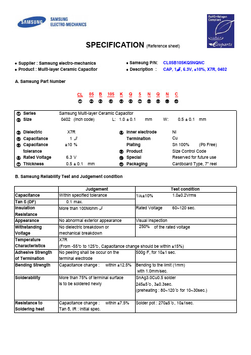
∙ Supplier : Samsung electro-mechanics ∙ Samsung P/N:CL05B105KQ5NQNC∙ Product : Multi-layer Ceramic Capacitor ∙Description :CAP, 1㎌, 6.3V, ±10%, X7R, 0402CL 05B 105K Q 5N Q N C ①②③④⑤⑥⑦⑧⑨⑩⑪①Series Samsung Multi-layer Ceramic Capacitor ②Size 0402(inch code)L: 1.0± 0.1mmW:± 0.1mm③Dielectric ⑧Inner electrode④Capacitance 1㎌Termination ⑤Capacitance±10%Plating (Pb Free)tolerance ⑨Product Size Control Code ⑥Rated Voltage 6.3V ⑩Special Reserved for future use ⑦Thickness0.5± 0.1mm ⑪PackagingCardboard Type, 7" reel Sn 100%Cu Ni X7R SPECIFICATION (Reference sheet)A. Samsung Part Number0.5B. Samsung Reliability Test and Judgement conditionCapacitance Within specified tolerance1㎑±10%1.0±0.2VrmsTan δ (DF)0.1max.Insulation More than 100Mohm ⋅㎌Rated Voltage60~120 sec.Resistance Appearance No abnormal exterior appearance Visual inspectionWithstanding No dielectric breakdown or of the rated voltageVoltage mechanical breakdown Temperature X7RCharacteristics (From -55℃ to 125℃, Capacitance change should be within ±15%)Adhesive Strength No peeling shall be occur on the 500g ·F, for 10±1 sec.of Termination terminal electrode Bending Strength Capacitance change :within ±12.5%Bending to the limit (1mm) with 1.0mm/sec.SolderabilityMore than 75% of terminal surface SnAg3.0Cu0.5 solder is to be soldered newly245±5℃, 3±0.3sec.(preheating : 80~120℃ for 10~30sec.)Resistance to Capacitance change : within ±7.5%Solder pot : 270±5℃, 10±1sec.Soldering heatTan δ, IR : initial spec.250%JudgementTest conditionVibration TestCapacitance change : within ±5%Amplitude : 1.5mmTan δ, IR : initial spec.From 10㎐ to 55㎐ (return : 1min.)2hours × 3 direction (x, y, z)Moisture Capacitance change :within ±12.5%With rated voltageResistanceTan δ : 0.125 max40±2℃, 90~95%RH, 500+12/-0hrsIR :More than 12.5㏁·㎌High Temperature Capacitance change :within ±12.5%With of the rated voltageResistanceTan δ : 0.125 max Max. operating temperatureIR :More than 25㏁·㎌1000+48/-0hrsTemperature Capacitance change :within ±7.5%1 cycle conditionCyclingTan δ, IR : initial spec.Min. operating temperature →25℃→Max. operating temperature →25℃5 cycle testC. Recommended Soldering method :Reflow ( Reflow Peak Temperature : 260+0/-5℃, 10sec. Max )Product specifications included in the specifications are effective as of March 1, 2013. Please be advised that they are standard product specifications for reference only.We may change, modify or discontinue the product specifications without notice at any time. So, you need to approve the product specifications before placing an order.150%JudgementTest conditionShould you have any question regarding the product specifications,please contact our sales personnel or application engineers.。
三星贴片电容系列规格书
All information indicated in this catalog is as of october. 2008 The specifications and designs contained herein may be subject to change without notice.
Packaging Specification
80
Packaging Specification
Application Manual for Surface Mounting
84
Application Manual for Surface Mounting
Please, see the last page of this catalog for our environ mental certification list.
�
�
Europe sales office
Frankfurt Office Samsung haus Am Kronberger Hang 6 D-65824 Schwalbach/Ts. Te l:49 - 6196 - 66 - 7255 FAX:49-(0)6196-66-7755 E-mail:frank.goebel@ Hungary Office H2310, Szigetszentmiklos, Leshegy u. 2-4, Hungary Te l:36-24-551-148 E-mail:jun21c.lee@
台湾信昌 MLCC(多层瓷介电容)推介资料

PDC -MLCC ProductsAS 9100C Aerospace Quality Management System航太品質管理系統認證TS 16949 Automotive Quality Management System汽車品質管理系統認證UL Safety Certified 安規認證Portfolios Series Size Dielectric Rating Volt CapacitanceGeneral Purpose FN Series0402 to 1812NPO/X7RX5R/Y5V≦100V≦0.82uFHigh Cap Mini-Volt.FS Series0402 to 1812X7R/X5RY5V≦50V1uF to 100uFHigh Cap Mid-Volt.FS Series1206 to 2225X7R50V to 100V0.68uF-10uF Middle Voltage FM Series0603 to 2225NPO/X7R≧100V to 630V≦1uFHigh Voltage FV Series1808/2211/2220NPO/X7R≧1000V≦68nF Safety Certificated FH & FK Series1206 to 2211NPO/X7R AC 250V≦4.7nF Military standard FM Series0603 to 2225NPO/X7R25V to 1000V Full range High Freq.RF & HH Series0201/0402NPO50V/100V≦1nFBig Size FG Series≧2220NPO/X7R25 to 3000V Full range Low D.F.FL Series Full range X7R250V/500V≦3.3nFSoft Terminal MLCC FP Series0805 up X7R≧100V to 3000V Full rangeMLCC Products≤630V≤50V10,000VAEC Q200High Cap1uF330uFH i g h V o lMEGA CAPM I L -S T DH i g h Q /R F /H CMid-Vol & High CapPDC MLCC Product Series MapSafety Certified MLCCSafety Capacitor Applications (X1/Y2 & X2)X1/Y2: TUV EN132400X2: TUV EN132400, UL60950Applications:Designed for AC surge and lightning protection in line-to-ground interface.1.Switching Power Supply2.Modems/ADSL/VOIP Ethernet Protection.(3KV~5KV/ AC250V)3.Computer networks.(3KV~5KV/AC250V)FH08X151K302EProduct Code FH:X2FK:X1Y2Chip Size 08:180812:181211:2211Dielectric N: NPO X: X7RCapacitance 151:15*101PFTolerance J : +/-5%K : +/-10%Rated Voltage X2Y3:302X1Y2:502Packaging E:EmbossedThickness E:1.65mm F:2.00mm G:2.50mmSpecial CodeG:Pb/Cd freeFGX1/Y2 X2AC Capacitors(Safety Capacitor ; X1/Y2 ;X2/Y3)IEC 60950(Telecom applications) T1=10us T2=700us IEC 60384-14(Power applications) T1=1.2us T2=50usRating Rated Voltage Vac Dielectric Withstanding Voltage Impulse Voltage Y2250Vac 1500Vac at 60Hz 5000V X1250Vac 1500Vac at 60Hz 4000V X2250Vac1500Vac at 60Hz2500VSeries Description WorkingVoltageImpulseVoltageT.C.C1808181222112220FK X1/Y2 Safety certified CapacitorUL/TUV(X1/Y2安規電容)AC250V5KVNPO271471721X7R102102222472FH X2 Safety certified CapacitorUL/TUV(X2安規電容)AC250V 2.5KVNPO102102X7R222562Interface Safety certified CapacitorSeries Description WorkingVoltageT.C.C120612101808181218252020221122202225FV High VoltageMLCC1000V-6000V(高壓電容)1KVNP0681102152222332332332332392X7R103103123473683683104104104 2KVNP0271561102122152152152152182X7R222222222472682682822822103 3KVNP0680221331471102102102102122X7R102182222222272272332 4KVNP0121221471471471471561X7R561821102102122122152 5KVNP0271331331471X7R821821102102 6KVNP0101101121151X7R681681821821FP Series Soft Termination MLCCCap Max .06030805120612101808181218252220222550V 104224105475335106106106100V 333224105225335106106106200V/250V 103333104684105225225275500V 223333124224684684105630V 2233331242246846841051KV 2233332735631041241542KV 2225625621032732733333KV222472123123153SizeRated VoltageThe capacitance listed in this table is the maximum available capacitance.FP Series Soft Termination MLCC•High performance to withstand 5mm bending test guarantee.PDC FP series is added a special termination material (Ultra-Buffer)between ceramic body and Ni-barrier that can absorb mechanical stress to prevent bending crack occurred.100% Sn External TerminaitonInner ElectrodeCu TerminationUltra-Buffer (Epoxy)Ni-barrier100% Sn External TerminaitonPDC FP Series solve risk of bending crack structureSoft termination products cross referencePDCMurataYageoSamsungTerminationInner layer Cu CuCu CuMiddle 1stlayerUltra-BufferConductive Cu polymerSoft electrodeSoft termination Flexible layerMiddle 2nd layer Ni Ni Ni Ni Outer layerSn SnSn Sn Coding rule(eg.0805)FP 21******GRJ 21**** / GCJ 21****CS 0805****CL*********4***/CL *********5***Bending Spec >=5mm >=3mm >=3mm Class Ⅰ:3mm; Class Ⅱ:2mmDielectric NP0/X7R X7R X7R C0G/X7R Size 0603~22250603~22200603~12060402~1206Rated Voltage 50V~3000V 10V~1000V 16V~630V 10V~100V Capacitance100pF~10uF1000pF~10uF100pF~1uF100pF~22uFFV Series Arc Prevention MLCCArc Prevention MLCCElectric ArcSurface CoatingChip Size1206180822112220 Voltage50V to 5000VDielectric Class II / Class IProduct rangeFE Series High Reliability Mega CapNo Part Material 1Ceramic DielectricBaTiO 32ElectrodeNi 3TerminationCu 4Ni 5Sn 6Joint High Temperatue Solder(Pb free)7Metal Lead Frame Cu AlloyMeg Cap Products SeriesHigh Reliability ProductsHigher Capacitance as same mounting area121018122220 / 1825 / 2225Stacked Chip Number CapacitanceStacked ChipNumberCapacitanceStacked ChipNumberCapacitance11time11time11time2 2 time2 2 time2 2 time3 3 time4 4 time More stacked chip number, more higher capacitance.Higher Capacitance as same mounting area1210181222201 stacked2 stacked 1 stacked 2 stacked 1 stacked 2 stacked3 stacked4 stacked TDK◎◎◎◎◎Murata◎◎◎◎◎PDC◎◎◎◎◎◎◎◎PDC could support higher capacitance products.Mega Cap Products SeriesFeature of each CapacitorsNormal MLCC Mega Cap Ta Cap ShapePolarity no no yes Bending Strength good excellent excellent Voltage Proof excellent excellent Bad ESR excellent excellent Bad Reliability good excellent BadPrice excellent good ExcellentMG/MT Series Automotive MLCCReliability AEC-Q200 QualifiedGrade 1Non AEC-Q200 qualifiedMost passenger compartmentGeneral Purpose MLCCNon AutomotiveStandard series(General purpose)MG / OP / SH / SGRF / HHMT / MY (array)RT / STMLCC series Automotive ApplicationDielectric NP0X7R X5RSize0402, 0603, 0805, 1206, 1210, 1812Capacitance range0.5pF to 0.033uF100pF to 2.2uF0.056uF to 10uF Rated voltage (WVDC)10V~630V 6.3V ~ 250V 6.3V, 10V, 16V, 25V Operating temperature-55 to +125°C-55 to +85°C Capacitance characteristic±30ppm/°C±15%Termination Ni/Sn (lead-free termination)MG series MLCC (Non AEC-Q200 series)MT series MLCC (AEC-Q200 Qualified series)Dielectric X7R NP0Range Size Rated voltage Capacitance range Size Rated voltage Capacitance range 040210~50V100~10nF040210V ~ 50V0.5pF ~ 1000pF060310~50V100pF~100nF060310V ~ 100V0.5pF ~ 1000pF 100V100pF~10nF200V0.5pF~100pF 080510~630V~1uF(25V), ~220nF(50V),~0.1uF(100V),~22nF(250V), ~10nF(630V)080510~50V0.5pF~ 4.7nF100V0.5pF~1nF 120610~50V220pF~1uF120610~100V 1.2pF~10nF100~630V220pF~220nF(100V)~22nF(250V), ~10nF(630V)200~630V 1.2pF~2.2nF1210250V10pF~3.9nFOperating temperature-55 to +125°C Standard series of Automotive MLCCRF Series Hi-Frequency MLCCFEATURES1.Made by BME technology with Cu inner electrodes.2.Excellent Q level at high frequency applications.3.Having high SRF characteristic.4.Offer ultra low capacitance to 0.1pF.5.Offer high precision capacitance tolerance to ±0.05pF6. Lead-free and Meet RoHSAPPLICATIONS1.Mobile phones and telecommunication equipments.2.Related to satellite equipments and products.3.RF Modules: Power amplifier, VCO.PDC’s RF03N-MLCC applied in WiFi 802.11 a/b/g/n/ac/ad module Dielectric NP0 characteristic Size Ultra-small : 01005Regular : 0201, 0402, 0603, 0805Square : 0505, 1111Rated voltage (WVDC)01005 : 16V/25V (New launch)0201 : 6.3V ~ 50V0402 : 50V ~ 200V0603 : 50V ~ 250V0805 : 50V ~ 500V0505 : 50V ~ 250V1111: 500V (New launch)PDC RF-series MLCCPDC classifies & provides different Q level of NPO-MLCCs fordifferent application fields and competitive prices .High Q / Low ESR MLCCs in Market RF-Series GJM/GQ M Series S-series ATC600HH-SeriesNormal NPO C-series L-series H i g h Q ATCGRMSeriesNormalwith Cu inner-electrode with Ag inner-electrodeATC800ATC100MLCC OEM/ODM SolutionsMLCC Big size Product MAP Rated Voltage50V100V200V/250V500V/630VDielectric X7R X7R X7R X7R 1210475225474563 1812275225105124 1825565475225334 2020565475225334 2220685475225474 2225685475225105 3035685475335125 3333825475335125 3530825475475125 3640825565475225 3940825655565225 4045106685565225 4238106685565335 4252106685685335* We also can provide customer made product range , please contact with PDC local representative.Application of CircuitFunction Product Type Capacitance Voltage Size MaterialSmoothing Low Volt.1uF ~100uF 3.3V/6.3V/10V/16V≦1206X7R/X5R Mid Volt.1uF~22uF25/50V≧1206X7R High Volt.0.1uF~4.7uF100V/250V/500V/1KV≧1206X7RDe-coupling High Volt.1p~33pF3000/5000/6000V≧1808NPOOscillation Low Vol.0.1nF~22nF10V/16V≦0805NPO High Vol.1nF~10nF250V/500V≧1210NPOSnubber High Voltage1nF~10nF100/250/500/1000V≧0805X7R Tuning High Freq.0.1p~1nF50V/100V≦0603NPOInterface High Volt.0.68~2.2nF2000V/3000V≧1206X7R Safety Cap0.68~2.2nF AC 250V≧1206X7RApplication of CircuitFunction Product Type Capacitance Voltage Size MaterialSmoothing 平滑電路FS Series1uF ~330uF 3.3V to 25V≦1206X7R/X5R FM/FS Series0.1uF~4.7uF100V/250V/500V≧1206X7REMI(De)Coupling (去)偶合FM/FV Series0.1nF~10nF250V/630V/1000V/3000V≧0805NPO/X7ROscillation振盪電路FM Series1nF~10nF250V/500V≧1210NPOSnubber 緩衝電路FM/FV Series1nF~10nF100/250/500/1000V≧0805X7RApplication of Power Circuit電源電路應用Smoothing Circuit (平滑電路)Series Description WorkingVoltageT.C.C120612101808181218252020221122202225FS Smoothing Function Capacitor≧50v ,1uF(濾波電容)50VX7R475225275565565685685X5R475106106100V X7R105225225475475475475200/250V X7R105225225225225FG Big size MLCC(大尺寸電容)50-10KV X7RChip Size 3035 to 13060 , Capacitance Please contactwith PDCEMI (De)Coupling Circuit/(去)偶合電路Series Description WorkingVoltageT.C.C120612101808181218252020221122202225FV High VoltageMLCC1000V-6000V(高壓電容)1KVNP0681102152222332332332332392X7R103103123473683683104104104 2KVNP0271561102122152152152152182X7R222222222472682682822822103 3KVNP0680221331471102102102102122X7R102182222222272272332 4KVNP0121221471471471471561X7R561821102102122122152 5KVNP0271331331471X7R821821102102 6KVNP0101101121151X7R681681821821L/C Oscillation Circuit 電感電容振盪電路Series Description WorkingVoltageT.C.C121018121825202022202225FM Middle Voltage MLCC100V-630V(中電壓電容)250V NPO392682822822822103500V NPO182332472472472682FL Low Dissipation MLCC(低損型電容)250V X7E154684500V X7E473Snubber circuit (緩衝電路)Series Description WorkingVoltageT.C.C0805120612101808181222112220FM Middle Voltage MLCC100V-630V(中電壓電容)250VNPO102222392682822X7R333104474105225 500VNPO391222182332472X7R223333563124474FV High Voltage MLCC1000V-6000V(高壓電容)1KVNP0681102152222332332X7R103103123473104104 2KVNP0271561102122152152X7R222222222472822822 3KVNP0680221331471102102X7R102182272272Series Description WorkingVoltageImpulseVoltageT.C.C1808181222112220FK X1/Y2 Safety certified CapacitorUL/TUV(X1/Y2安規電容)AC250V5KVNPO271471721X7R102102222472FH X2 Safety certified CapacitorUL/TUV(X2安規電容)AC250V 2.5KVNPO102102X7R222562Interface Safety certified CapacitorSeries Description WorkingVoltageT.C.C120612101808181218252020221122202225FV High VoltageMLCC1000V-6000V(高壓電容)1KVNP0681102152222332332332332392X7R103103123473683683104104104 2KVNP0271561102122152152152152182X7R222222222472682682822822103 3KVNP0680221331471102102102102122X7R102182222222272272332 4KVNP0121221471471471471561X7R561821102102122122152 5KVNP0271331331471X7R821821102102 6KVNP0101101121151X7R681681821821Thank You。
电磁屏蔽材料产品手册

MIL-G-83528
>0.9
>0.9
>0.9
NS
0.1
Para4.6. 16(Q)
75
导电橡胶条
说明 :
连续的挤出技术被应用在这种产品上,挤出类橡胶有连续的长度,特别适用于大规模的应用。这种类型的 产品可以根据客户的截面要求进行定制,可以灵活的满足不同的应用要求。
典型应用:
射频单元的电磁和环境密封 通信及军用机柜 医疗设备 铁路应用
产品特征:
主要用于要求水密、气密或频率范围特别宽,并需要优良屏蔽性能的场合
典型应用:
航空、航天、舰船等军用方舱和军用电子设备 境恶劣的电子设备
电子产品、电信、高频控制设备
电力、铁路等环
导电橡胶板
型号
22051-XX 22081-XX 22102-XX 22157-XX 22190-XX 23051-XX 23081-XX 23102-XX 24051-XX
尺寸(mm)
W
T3.181.源自73.961.57
6.35
1.57
12.70
1.91
1. 0160-0107-XX : 1215: Ag/Cu(银铜) 1285:Ag/Al(铝镀银) 1350:Ag/Glass(玻璃镀银) 6305:NiC(石墨镀镍)
D 形实心导电橡胶条
型号
0157-0216-0079-XX 0178-0241-0089-XX 0203-0178-0102-XX 0260-0292-0130-XX 0318-0318-0157-XX 0478-0478-0239-XX
5.80
4.20
77
1.
0157-0216-0079-XX :
MLC程式手册

目录页次第一章概论1.1M LC简介----------------------------------------------------- 1 1.2M LC与C N C界面------------------------------------------ 2 1.3M LC系统分析----------------------------------------------- 4 1.4M LC关联模块----------------------------------------------- 6 1.5M LC操作流程-----------------------------------------------8第二章启动MLC系统2.1 系统需求-----------------------------------------------------------10 2.2 启动MLC系统-----------------------------------------------------11 2.3 MLC的屏幕规划--------------------------------------------------12 2.4 案件操作说明-----------------------------------------------------14第三章阶梯图程序设计3.1 开档------------------------------------------------------------------ 16 3.2 元见输入------------------------------------------------------------17 3.2.1 接点元见----------------------------------------------------------18 3.2.2 输出元见----------------------------------------------------------20 3.2.3 定时器元见-------------------------------------------------------21 3.2.4 计数器组件-------------------------------------------------------22 3.2.5 跳耀组件----------------------------------------------------------22 3.2.6 算术操作数件---------------------------------------------------- 23 3.2.7 标记组件----------------------------------------------------------24 3.2.8 返回组件----------------------------------------------------------24 3.2.9 刀具组件----------------------------------------------------------25 3.2.10 功能切换组件--------------------------------------------------253.3 档案编辑------------------------------------------------------------263.3.1 列插入键-------------------------------------------------------263.3.2 删除键----------------------------------------------------------263.3.3 Mark 编辑键---------------------------------------------------273.3.4 寻找键-----------------------------------------------------------273.3.5 结束编辑键----------------------------------------------------- 28第四章编辑、模拟、打印及合并4.1 编辑模点--------------------------------------------------------------29 4.2 仿真模块--------------------------------------------------------------304.2.1 I/O/C/S/A 的状态----------------------------------------------314.2.2 定时器/技术器/缓存器状态---------------------------------32 4.3 打印模块---------------------------------------------------------------33 4.4 合并模块---------------------------------------------------------------33第五章MLC 的特殊功能5.1 呼叫 C 语言子程序------------------------------------------------345.1.1 C 语言子程序部分-----------------------------------------345.1.2 C 阶梯图程序部分-----------------------------------------36 5.2 换刀功能--------------------------------------------------------------- 375.2.1 换刀的动作原理----------------------------------------------375.2.2 阶梯图程序之换刀元键设计------------------------------37附录附率A MLC 功能架构图---------------------------------------------A-1 附录B MLC 元键指令表--------------------------------------------- A-3 附录C 元键指令说明--------------------------------------------------A-5 附录D CSR.C-------------------------------------------------------------A-30 附录E C 语言函数库-------------------------------------------------- A-32 附录F D 阶梯图程序---------------------------------------- A-33 附录G 换刀阶梯图程序D------------------------------- A-34第一章概论1.1MLC 简介机械逻辑控制器(MLC)系作为机械接口和CNC接口讯号的逻辑控制, 为区别与一般可程控器(PLC)应用对象不同, 在此我们特别将在CNC控制器上发展的可程控器称为机械逻辑控制器, 以别于一般的PLC , 以下以MLC 来描述此套可程控系统。
formulations 配方
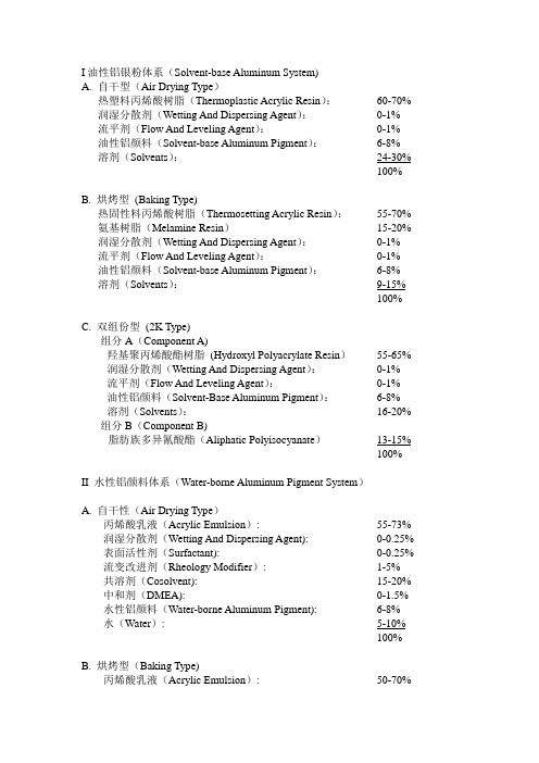
I油性铝银粉体系(Solvent-base Aluminum System)A.自干型(Air Drying Type)热塑料丙烯酸树脂(Thermoplastic Acrylic Resin):60-70% 润湿分散剂(Wetting And Dispersing Agent):0-1% 流平剂(Flow And Leveling Agent):0-1% 油性铝颜料(Solvent-base Aluminum Pigment):6-8% 溶剂(Solvents):24-30%100% B. 烘烤型(Baking Type)热固性料丙烯酸树脂(Thermosetting Acrylic Resin):55-70% 氨基树脂(Melamine Resin)15-20% 润湿分散剂(Wetting And Dispersing Agent):0-1% 流平剂(Flow And Leveling Agent):0-1% 油性铝颜料(Solvent-base Aluminum Pigment):6-8% 溶剂(Solvents):9-15%100% C. 双组份型(2K Type)组分A(Component A)羟基聚丙烯酸酯树脂(Hydroxyl Polyacrylate Resin)55-65% 润湿分散剂(Wetting And Dispersing Agent):0-1%流平剂(Flow And Leveling Agent):0-1%油性铝颜料(Solvent-Base Aluminum Pigment):6-8%溶剂(Solvents):16-20% 组分B(Component B)脂肪族多异氰酸酯(Aliphatic Polyisocyanate)13-15%100%II 水性铝颜料体系(Water-borne Aluminum Pigment System)A. 自干性(Air Drying Type)丙烯酸乳液(Acrylic Emulsion): 55-73% 润湿分散剂(Wetting And Dispersing Agent): 0-0.25% 表面活性剂(Surfactant): 0-0.25% 流变改进剂(Rheology Modifier): 1-5%共溶剂(Cosolvent): 15-20% 中和剂(DMEA): 0-1.5% 水性铝颜料(Water-borne Aluminum Pigment): 6-8%水(Water): 5-10%100% B. 烘烤型(Baking Type)丙烯酸乳液(Acrylic Emulsion): 50-70%润湿分散剂(Wetting And Dispersing Agent): 0-1%交联剂(Crosslinker)1-4%催化剂(Catalyst)0-1%共溶剂(Cosolvent): 1-5%中和剂(DMEA): 0-1%水性铝颜料(Water-borne Aluminum Pigment): 6-8%水(Water): 22-30%100% C. 双组份型(2K Type)组分A(Component A)脂肪酸聚氨酯分散体(Aliphatic Ployurethane Dispersion):20-40% 润湿分散剂(Wetting And Dispersing Agent) :消泡剂(Defoamer) :1-3%流变改进剂(Rheology Modifier) :1-3%共溶剂(Cosolvent) :5-10%中和剂(DMEA) :0-1%水性铝颜料(Water-borne Aluminum Pigment) :6-8%水(Water):45-50% 组分B(Component B)脂肪酸多异氰酸酯(Aliphatic Polyisocyanate):2-4%100%5ZN2F-C6NTT-ZPBWP-L2DWY-Y4B495ZN2F-C6NTT-ZPBWP-L2DWS-Y4B495ZN2F-C6NTT-ZPBWP-W2DW3-D4B495ZN2F-C6NTT-ZPBWP-W2DW3-C4B495ZQ2B-NI239-4F4K7-H9N8Q-VTSYT5ZQ2A-NI236-4F4K7-H9N8Q-VTSYT5ZQ2A-NI236-4F4KY-H9N8Q-VTSYT5RP2E-EPH3K-BR3LG-KMGTE-FN8PY。
GRM31CR71H225KA88L中文资料
物料编号:GRM31CR71H225KA88L细参数_易容网
MLCC即是多层陶瓷电容片式,是电子信息产品不可或缺的基本组件之一。
我国MLCC的生产起步在80年代初,行业早期主要是在外资企业的带动下发展起来的,近年来国内企业在技术上实现突破,行业国产化成效显著,并推动了MLCC产量迅速增长。
目前,MLCC的应用领域已从手机、电脑、电视机等消费电子领域,逐步拓展到新能源发电、新能源汽车、节能灯具、轨道交通、直流输变电、三网融合、高清电视、机顶盒、手机电视等多个行业。
对于这个悄悄活跃在人们生活中的元件你又知道多少呢.
本次易容网为大家推荐比较常用的MLCC村田 | Murata品牌的料号GRM31CR71H225KA88L的相关参数
易容网是深圳市易容信息技术有限公司独自研发的全球最大的MLCC搜索采购服务网站,2014年创立于深圳市南山区,全国首家电子元器件行业电容元件的搜索引擎及o2o商务服务平台。
易容网()现已建成全球最大的MLCC电容搜索引擎数据库,包含全球25家电容生产厂商超过28万组MLCC产品数据,用户可根据行业应用、物料编号、规格参数等信息快速的找到所有相关的MLCC电容数据。
易容网在搜索服务的前提下还提供村田、TDK、国巨、太阳诱电、风华高科等常见品牌产品的o2o商务服务,让企业客户实现询价、报价、在线订单、出库、实时物流、签收、账期服务等在线一站式商务服务体验。
铝锅涂料基本知识

10
2020/5/14
易宝龙一般是针对终端客户的,就是客户 指定要这样的涂料。
ILAG ULTIMATE
ILAG PREMIUM ILAG SPRCIAL ILAG BASIC
2020/5/14
7
2020/5/14
钛是具有非常出色的最强硬耐磨、最轻的金属。 华福的quantanium不粘涂料把钛金属从航太领域带 进了厨房
耐磨性能仅次于Excalibur,甚至可使用金属锅铲, 在欧美市场拥有很高的知名度,在高档厨具中得到 了广泛的应用。
表面光泽度很高,无需添加特别设备,使用传统 的喷涂设备就行。
2020/5/14
15
2020/5/14
德国威堡和威堡龙品牌均隶属于有180年 历史的德国Grebe工业涂料制造集团。
集团成员遍布全球,是全球最大的家居用
品表面处理供货商之一和欧洲最大的轨道车 辆供货商。旗下的炊具、家居涂料隶属于威 堡龙品牌, 德国威堡品牌则涵盖了以轨道车 辆为主的所有特种工业涂料。
12
杜邦公司于2012年在 成都设立西部地区 首家分公司,与合作伙伴协力提升本地化创 新,支持中国西部大开发战略。经过29年的 努力,杜邦已在中国建立了50余家独资及合 资企业,拥 有员工约7500人,并将许多地区 业务总部移至中国大陆。
2020/5/14
TEFLON CLASSIC
TEFLON XTRA
2020/5/14
9
2020/5/14
易宝龙是FLH控股集团旗下的独立运营的 全资子公司ILAG Industrielack的产品。ILAG Industrielack是一家瑞士企业,于1955年在瑞 士成立,专业生产应用于园林工具食物炊具的 不粘耐磨涂料。FLH 集团于06年在上海成立 了分公司,就叫上海易能涂料有限公司,专业 从事高性能涂料的生产销售和技术服务。
瓷片电容规格CT1206X7R222K202NT

浸锡温度:235±5℃ ; 浸锡速度:25±0.25mm/s
浸锡时间:2±0.5sec
創天電子科技有限公司
SUNBEAM ELECTRONIC LTD
Tel: +86- 020-82089712 82089108 Fax: +86-020-82214330
3
耐焊接热 端电极
附着强度 抗弯曲强度
温度循环
按以下温度顺序,温度稳定30min后测定(△C以T3为准)
步骤
温度(℃)
T1
20±2
T2
下限类别温度(如 X7R -55±3)
T3
20±2
T4
上限类别温度(如 X7R 125±2)
T1
20±2
将电容器浸在乙醇和松香(占25%重量)溶液中,取出在 80~120℃的温度下预热10~30sec,再浸入焊锡溶液。
前两位数字为有效数字,后一位数字为10的指数,
102
10×102
R为小数点
104
10×104
④容量误差级别
代码
A
B
C
D
F
G
J
K
M
误差 ±0.05pF ±0.10pF ±0.25pF ±0.50pF ±1.0% ±2.0% ±5.0% ±10.0% ±20.0%
备注
A、B、C、D误差级别一般用于≤10pF的容量
版本:F
1
型号规格表示方法
1206 X7R
222
K
202
N
T
说明: ①尺寸 尺寸规格
① 0402
② 0603
③ 0805
④ 1206
⑤ 1210
⑥ 1808
MLB MLD MLC ML系列执行器说明书

37.2
16.0
2X MOUNTING HOLES M5X0.8 7mm
A 15.5
13.8
SHAFT ONLY
6.7 6.0
5.2 DETAIL A
(1) EXTERNAL LINEAR GUIDE
45.5
(2) EXTERNAL LINEAR GUIDE
58.0
DOVETAILS
14.3
2.0
2X 60°
1.0
TYP
7.6
5.2
TYP
TYP
45°
TYP
21.9
DOVETAIL SLOTS
CARRIAGE ONLY
T-SLOTS 29.3
DOVETAIL SLOTS
NO DOVETAIL
31.4
39.3
39.3
WITH
DOVETAIL
AVAILABLE IN LEFT OR RIGHT SIDE MOUNT
0.06
0.13
Add for 100 mm of stroke Total Carriage Mass
0.15
0.34
Kg
lbf
0.020
0.044
Total Carriage Mass & Top Plate
0.059
Coefficient of Friction
0.19
Max. Speed
m/s 1.9 in/s
0.130
75 25.6 0.2 0.375
0.50 0.94 0.062
0.15 0.30
0.25 0
.0006
LOAD RANGE
80% CRITICAL SPEED
物料描述规范
物料描述规范总体规格描述中要含下列内容及顺序:另外如物料无法有描述来全部或精准描述其特性时须由开发部出相应物料的样品技术要求文件,如外形尺寸不规格的散热器,外壳,变压器等。
1.类别如IC ,MOSFET, RES, DIODE, CAP等;2.封装如贴片SMD 0805,插件THD SOP-8,TO-220F;3.型号标识MARKIC IW16924.规格如电压,电流,阻值,容量,感量,误差,外型尺寸,功率,材质等;5.包装类型如散装BULK,编带TAPE,编盘REEL,管装TUBE;真空包装vacuum-packed;具体分类说明:1.贴片电阻描述:名称+阻值+误差+功率封装+包装;RES SMD1206 1.2M(125) 1/4W +/-5% REEL;2.插件电阻描述:名称+材质+阻值+误差+功率+形状+包装;RES Carbon Film 1R +/-5% 2W AXIAL TAPE;3.贴片MLC电容描述:名称+材质+容值+电压+误差+封装+包装;CAP CER SMD 0805 68PF +/-5% 50V NPO REEL;4.铝电解电容:名称+容值+误差+纹波电流+耐温+是否高频低阻+寿命时间+尺寸+包装;CAP AEL 4.7UF +/-20%5.0*12*20 50V 105℃100MAripple Cur. Lower ESR 2000Hrs TAPE;5.插件无极性电容:材质+容值+误差+耐温+耐压+尺寸+包装;CAP Ceramic 1000PF(102) 1KV 85℃X7R 9.8*5*11.3MM跨脚宽度>6.4MM TAPE;6.电感料描述:感量+材质+误差+尺寸(封装/功率)+包装;IND THD铁氧体8*10 1.6MH+/-10% BULK;IND THD 绕线电感1MH+/-10% 1W TAPE;7.二极管描述:型号名称+参数(电压、电流)+尺寸(封装)+包装;DIODE THD HER203 2A/200V,D0-15 TAPE;DIODE SMD IN4148 100MA/75V REEL;8.IC类描述:型号+性能规格+封装+品牌+备注(是否烧录)包装;IC TL431 Vref=2.5V +/-0.5%,TO-92 UTC TAPE.IC IW1692 SOT-23-6 ,IWATT TUBE;9.晶体管描述:型号+耐压+ICE电流+放大倍数+(品牌))+封装+包装;Transistor NPN THD 13003 800MA/500V Hfe>30, T0-126(ST)BULK; Transistor PNP SMD MMBT3904 40V 200mA SOT-23 REEL;10.MOS管描述:型号名称+耐压+结温+封装+品牌+包装;MOSFET THD N-CH 2A 600V TO-251 155℃ST TUBE11.指示灯描述:名称+颜色+耐压特性+封装尺寸+包装;LED THD ¢3MM,绿光,30V BULK;12.PCB板描述:型号名称+材质+厚度+铜泊厚度+防火等级+版本+包装;PCB FR4 1.0t 1oz Double-sided 78.6*44mm 铜箔半盎司94V0, vacuum-packed KS-Y28050-B2 REV1.0;13.保险丝描述:型号+材质(如玻璃,陶瓷)++快/慢断+电压、电流+尺寸+安规(UL/VDE等)+包装;FUSE T2A 250V GLASS ∮3.6*10mm UL BULK;14.变压器:型号+感量+漏感+误差+包装;Transformer THD L=1620uH±4% RM8 KS-Y40035-L2-T-REV1.0;15.跳线描述:材质+尺寸,直径+包装;JUMP 铜¢0.8MM 5CM BULK;16.螺丝描述:名称+规格尺寸+表面处理++包装;SCREW ¢3MM 长20MM 十字型自功螺丝镀彩锌BULK;17.接插件描述:名称+规格尺寸+材质+防火等级+包装;SOCKET 5PIN PIN间距2MM PC 94V0 BULK;18.振荡器描述:名称型号+材质+频率+误差+负载电容+封装+包装;OSCILLATOR CRYSTAL 27MHZ +/-10PPM 10NF 20*8*10 TUBE;19.塑胶、料描述:型号名称+材质+颜色+丝印等备注+包装;胶壳ABS+PC(GE料)黑色94V0 喷纱,最好用技术要求文件说明;20.线材描述:型号名称+规格+牲性要求(材质+股数+安规与否)+包装;Line AC INPUT L=43mm +/-2mm White UL1332 #22, 最好用技术要求文件说明;21.铜线描述:名称+直径+耐温等级+颜色+包装;漆包线¢1.0MM 155℃漆黑色REEL;22.套管描述:规格名称+尺寸+材质+颜色+耐温要求+安规+包装;TEFLON25#销银特多龙¢3MM 15*4mm 200℃REEL;23.磁芯描述:名称+材质+规格尺寸+AL值+包装;PQ3235 PC40 32*35MM AL=2000LP/N*2 BULK;以下项物料最好以技术文件要求说明:24.胶芯骨架描述:名称+材质+尺寸+包装;25.胶带描述:名称+材质+规格尺寸+颜色+安规等级+包装;26.标贴描述:型号名称+规格尺寸+材质+安规+包装;27.彩盒彩卡、包装箱、说明书描述:型号名称+规格尺寸+材质+包装;28.泡沫吸塑描述:名称+材质+规格尺寸+颜色+安规等级+包装;29.贴纸胶袋描述:名称+材质+规格尺寸+包装;五金类描述:名称+材质+规格尺寸+包装;文案编辑词条B 添加义项?文案,原指放书的桌子,后来指在桌子上写字的人。
里奇利朗的瓷制门面和电器面板说明书
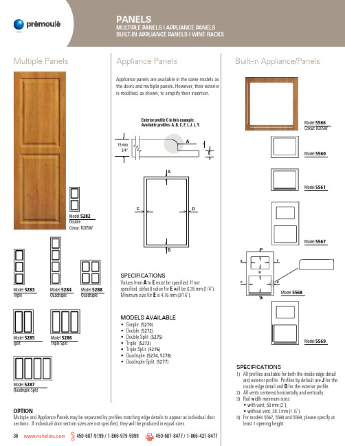
CB 45°45°450-687-9199 / 1-866-979-5999450-687-8477 / 1-866-421-8477 37Model 5138Colour: R204WModel 5143Colour: R205WModel 5134Colour: R204W Model 5133Colour: R204WModel 5132Colour: R204WWine RacksCIRCLE SHAPEDSPECIFICATIONS• If models 5132 and 5133 are paired together, it must bes pecified when placing your order.• Minimum size: 5132: 76.2 mm (3") height 5133: 69.8 mm (2 3⁄4") heightSPECIFICATIONSOpening size: 101.6 x 101.6 mm (4" x 4")SPECIFICATIONS1) Standard Hole Diameter: 101.6 mm (4")2) Distance between holes: 133.4 mm (5 1⁄4")3) A = [Width – (number of holes – 1) x 133.4 mm] ÷ 2 [Width – (number of hole – 1) x 5 1⁄4"] ÷ 2B = [Height – (number of hole – 1) x 133,4 mm] ÷ 2 [Height – (number of hole – 1) x 5 1⁄4"] ÷ 24) A or B minimum size: 76.2 mm (3")Model 5141Colour: R205W Model 5142Colour:R205W X SHAPED38 450-687-9199 / 1-866-979-5999450-687-8477 / 1-866-421-8477SERIE 69006507660765096609690769096505660569106912manufactured with 09 interior profile.Model 4106SPECIFICATIONS1) For special mullion frames (except series 6900) where the mullion bars line-up h orizontally,the door widths must be identical.2) An interior profile must be specified for models 000, 911, 912 (profile 09 by default) and910 (profile 151 by default) frame or mullion doors.3) Series 83 to 89 are only available in special mullion door models 6706, 6708, 6909 and 6912. This restrictiondoes not apply to series 93 to 99.4) Models 928, 942, 943 and 944 are available only in 4100 series.5) Model 996 frame and mullion doors are available only in 4100 series.6) Mitre style models 7730-31-32, 7930-31-32 and 928 are not available with glass retainerinsert grooves.COLOURS AVAILABLE• Clear (5351)• White (5350)Minimum sizesLites Height x Widthmm inches01 203.2 x 203.2 8 x 802 279.4 x 203.2 11 x 803 368.3 x 203.2 14 1⁄2 x 804 279.4 x 279.4 11 x 11 06 368.3 x 279.4 14 1⁄2 x 11 08 457.2 x 279.4 18 x 11 10 546.1 x 279.4 21 1⁄2 x 11 12 635.0 x 279.4 25 x 11GLASS INSTALLATION450-687-9199 / 1-866-979-5999450-687-8477 / 1-866-421-8477 41INSTALLATION Model 741Model 745Model 746Model 751Model 743Model 5718Model 5719Model 756Model 757Model 721SPECIFICATIONNailing strips should be glued and clamped rather than nailed.METHOD 1METHOD 242 450-687-9199 / 1-866-979-5999450-687-8477 / 1-866-421-8477 SPECIFICATIONS1) Only the bottom edge is p rofiled. Please specify the edge profile.2) Rosettes are centered v ertically in the A dimension and horizontally in the E dimension.3) Woodgrain pattern is parallel to width. (Certain exeptions may apply, please contact a Customer Sevice Representative for further information.)> 203.2 mm (8"), 5610 plain101.6 4 330.2 135611 with 2 routed circles 101.6 4 330.2 135616 with 2 applied rosette 101.6 4 330.2 135620 plain101.6 4 304.8 125621 with 2 routed circles 101.6 4 304.8 125626 with 2 applied rosette 101.6 4 304.8 125630 plain101.6 4 304.8 125631 with 2 routed circles 101.6 4 304.8 125636 with 2 applied rosette 101.6 4 304.8 125640 plain 101.6 4 254 105650 plain 101.6 4 152.4 63" Radius Corners Shaker Filler450-687-9199 / 1-866-979-5999 450-687-8477 / 1-866-421-8477 43I IT IHeatshield fillers are higher heat resistant fillers for kitchen c abinet installations where heat sources are ac oncern.HPL Heatshield fillers are pretested to temperatures above 120 °C (250 °F) without delamination, theHPL Heatshield Fillers are postformed 180° profiled components.Produced with compatible HPL, they are available in most colours. Please contact a Customer ServiceRepresentative for an up-to-date list of available colours.Heatshield Fillersedgebanding machines operating tandard edgebanding machines run at 88 °C (190 °F) to 99 °C (210 °F), we also offer PVC edgebanding which can be applied with the standard machines. Available finishes for each type of edgebanding are listed in the If A or B sizes are between: 101.6 mm (4") – 152.4 mm (6"), R = 101.6 mm (4")152.4 mm (6") – 203.2 mm (8"), R = 152.4 mm (6")203.2 mm (8") – 254 mm (10"), R = 203.2 mm (8")254 mm (10") – 381 mm (15"), R = 254 mm (10")NOTE: Minimum size for A and Bis 89 mm (3 ½")Corner ShelvesSHELF WITH RADIUSSHELF WITH ELLIPSEIf A R If A R Model 5120Model 5121Thermoplastic 1.2 m x 2.4 m (4’ x 8’) (5040)Laminated Panels – Unilam 5011 : 15.86 mm x 1.2 m x 2.7 m (5/8’’ x 4’ x 9’)5013 : 15.86 mm x 1.2 m x 2.4 m (5/8’’ x 4’ x 8’)5015 : 19.05 mm x 1.2 m x 2.4 m (3/4’’ x 4’ x 8’)NOTE: Available same colour back.1. 2. Duration3. Exclusions4.5.6.Starting on January 1 2011 (see conditions on reverse)DistributorInvoice #Date of purchaseY E A R SCERTIFICATE OFWARRANTYAPPLICABLE TO THERMOPLASTIC PRODUCTSPrémoulé supports05/20 BRPOLYDOORCDNServing you across North AmericaCANADAT 450-687-9199 / 1-866-979-5999F 450-687-8477 / 1-866-421-8477*************************Distributed byVisit our website and try our step-by-step quick and simple web module under the Cabinet Doors Section。
红宝石电解电容产品一览表及规格书
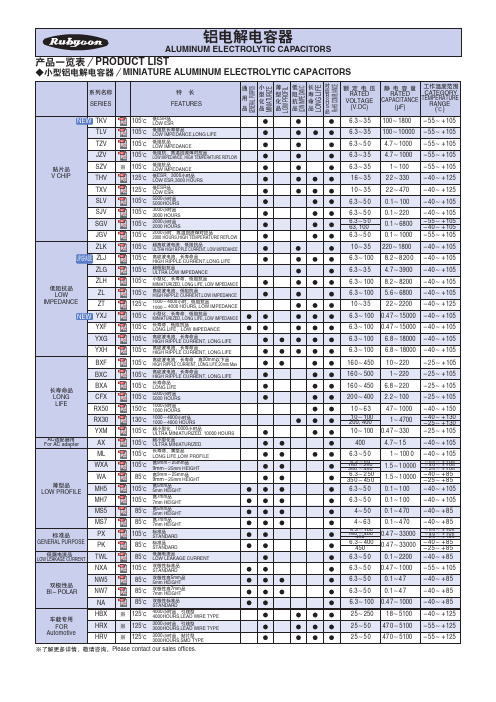
TEMPERATURE
RANGE (ņ)
6.3ċ3 5 6.3ċ3 5
100ċ1800 lj55ċLJ105 100ċ10000 lj55ċLJ105
6.3ċ5 0 6.3ċ3 5
4.7ċ1000 lj55ċLJ105 4.7ċ1000 lj55ċLJ105
6.3ċ3 5 16ċ3 5
1ċ100 2 2ċ330
lj55ċLJ105 lj40ċLJ125
Քጚ STANDARD
ୁۉگ LOW LEAKAGE CURRENT
ມटႠ BIljPOLAR
NXA NW5 NW7
105ņ 85ņ 85ņ
ມटႠՔጚ STANDARD
ມटႠߛ5mm 5mm HEIGHT
ມटႠߛ7mm 7mm HEIGHT
NA
85ņ
ມटႠՔጚ STANDARD
כሜጆᆩ
YXF
105ņ
ంĂگፆੇ LONG LIFEĂLOW IMPEDANCE
YXG
105ņ
ߛ࿖հୁۉĂం HIGH RIPPLE CURRENT, LONG LIFE
YXH
105ņ
ߛ࿖հୁۉĂం HIGH RIPPLE CURRENT, LONG LIFE
BXF
4ċ6 3
6.3 ċ100 160 ċ400
450
6.3ċ400 450
6.3ċ5 0
0.1ċ4 70 0.4 7ċ33000 0.4 7ċ33000
0.1ċ2200
lj40ċLJ85
lj5 5ċLJ105 lj4 0ċLJ105 lj2 5ċLJ105
lj4 0ċLJ8 5 lj2 5ċLJ8 5
lj40ċLJ85
MLC检查缺陷汇总、分析
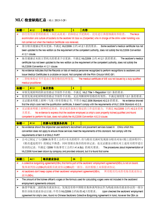
MLC检查缺陷汇总(截止2013-5-29)
1上述红色字体的缺陷描述存在不同程度和类型的问题,需要注意改进。
2 所有缺陷的纠正与预防措施必须在签发/签署MLC证书或符合证明前由船东或船方代表船东制定,并得到检查员认可。
对于严重缺陷,必须根据船旗国和/或总部指令在开航前予以纠正或降级。
船东或船方代表船东制订的纠正及预防措施时一般应考虑:
1)分析缺陷产生的根本原因;
2)视缺陷的性质决定是否应在开航前纠正,或允许开航后一定时间内纠正;
3)对允许开航后纠正的一般缺陷,船东制订的纠正措施计划完成期限不得超过三个月;
4)应针对缺陷制订预防措施;
5)明确缺陷纠正的责任人;
6)满足船旗国的特殊要求(如有时)。
三星电子多层陶瓷电容商品说明书

● Supplier : Samsung Electro-Mechanics CL10B103KA8WPNC● Product : Multi-layer Ceramic CapacitorCAP, 10㎋, 25V, ± 10%, X7R, 0603● AEC-Q200 QualifiedA. Dimension● DimensionB. Samsung Part NumberCL 10B K A 8W P N C ①②③⑤⑥⑦⑧⑨⑩⑪①Series Samsung Multi-layer Ceramic Capacitor ②Size (inch code)L :1.60±0.10 mm W :0.80±0.10 mm ③Dielectric ⑧Inner electrode Ni, Open Mode Design ④Capacitance ㎋Termination Metal-Epoxy ⑤Capacitance ± 10%Plating Sn 100% (Pb Free)tolerance ⑨Product Automotive ⑥Rated Voltage V⑩Special code Normal⑦Thickness0.80±0.10 mm⑪PackagingCardboard Type, 7" ReelTest items High Temperature Appearance : No abnormal exterior appearance Unpowered,1,**********************ExposureCapacitance Change Within ±10 %Measurement at 24±2hrs after test conclusion Tan δ :0.03 max.IR :More than 10,000 ㏁ or 500 ㏁×㎌Initial Measurement 2* Whichever is smallerFinal Measurement 3*Temperature Cycling Appearance : No abnormal exterior appearance1,000CyclesCapacitance Change Within ±10 %Initial Measurement 2* Tan δ :0.03 max.Final Measurement 3*IR :More than 10,000 ㏁ or 500 ㏁×㎌Measurement at 24±2hrs after test conclusionWhichever is smaller1 cycle condition : -55+0/-3℃(30±3min) → Room Temp. (1min)→ 125+3/-0℃(30±3min) → Room Temp. (1min)Destructive Physical No Defects or abnormalities Per EIA 469Analysis Humidity BiasAppearance : No abnormal exterior appearance 1,000hrs 85℃/85%RH, Rated Voltage and 1.3~1.5V,Capacitance Change Within ±12.5 %Add 100kohm resistor Tan δ :0.035 max.Initial Measurement 2* IR :More than 500 ㏁ or 25 ㏁×㎌Final Measurement 4*Whichever is smallerMeasurement at 24±2hrs after test conclusion The charge/discharge current is less than 50mA.High Temperature Appearance : No abnormal exterior appearance 1,000hrs @ 125℃, 200% Rated Voltage,Operating LifeCapacitance Change Within ±12.5 %Initial Measurement 2* Tan δ :0.035 max.Final Measurement 4*IR :More than 1,000 ㏁ or 50 ㏁×㎌Measurement at 24±2hrs after test conclusion Whichever is smallerThe charge/discharge current is less than 50mA.Specification of Automotive MLCC (Reference sheet)103L W T ● Samsung P/N :● Description :0.30±0.20 mmBWSize 0603 inch 1.60±0.10 mm 0.80±0.10 mm 0.80±0.10 mm X7R PerformanceTest condition25④060310External VisualNo abnormal exterior appearance Microscope (´10)Physical Dimensions Within the specified dimensions Using The calipersMechanical ShockAppearance : No abnormal exterior appearance Three shocks in each direction should be applied along Capacitance Change Within ±10 % 3 mutually perpendicular axes of the test specimen (18 shocks)Tan δ, IR :Initial spec.Initial Measurement 2* Final Measurement 5*VibrationAppearance : No abnormal exterior appearance 5g's for 20min., 12cycles each of 3 orientations,Capacitance Change Within ±10 %Use 8"×5" PCB 0.031" Thick 7 secure points on one long side Tan δ, IR :Initial spec.and 2 secure points at corners of opposite sides. Parts mounted within 2" from any secure point. Test from 10~2,000㎐.Initial Measurement 2* Final Measurement 5*Resistance to Appearance : No abnormal exterior appearance preheating : 150℃ for 60~120 sec.Solder HeatCapacitance Change Within ±10 %Solder pot : 260±5℃, 10±1sec.Tan δ, IR :Initial spec.Initial Measurement 2* Final Measurement 3*ESDAppearance : No abnormal exterior appearance AEC-Q200-002 or ISO/DIS10605Capacitance Change Within ±10 %Initial Measurement 2* Tan δ, IR :Initial spec.Final Measurement 4*Solderability95% of the terminations is to be soldered a) Preheat at 155℃ for 4 hours, Immerse in solder for 5s at 245±5℃evenly and continuouslyb) Steam aging for 8 hours, Immerse in solder for 5s at 245±5℃c) Steam aging for 8 hours, Immerse in solder for 120s at 260±5℃solder : a solution ethanol and rosinElectrical Capacitance : Within specified tolerance *A capacitor prior to measuring the capacitance is heat treated at CharacterizationTan δ :0.025 max.150 +0/-10℃ for 1hour and maintained in ambient air for 24±2 hours IR(25℃) :More than 10,000 ㏁ or 500 ㏁×㎌The Capacitance / D.F. should be measured at 25℃,Whichever is smaller1 ㎑ ± 10%,1 ± 0.2 VrmsIR(125℃) More than 1,000 ㏁ or 10 ㏁×㎌I.R. should be measured with a DC voltage not exceeding Whichever is smallerRated Voltage @25℃, @125℃ for 60~120 sec.Dielectric StrengthDielectric Strength : 250% of the rated voltage for 1~5 seconds Board FlexAppearance : No abnormal exterior appearance Bending to the limit,3 ㎜ for 60 seconds 1*Capacitance Change Within ±10 %Initial Measurement 2*Final Measurement 5*Terminal Appearance : No abnormal exterior appearance 10 N, for 60 sec.Strength(SMD)Capacitance Change Within ±10 %Initial Measurement 2* Final Measurement 5*Beam Load Destruction value should be exceed 20 NBeam speed :0.5±0.05 ㎜/secTemperature X7RCharacteristicsFrom -55 ℃ to 125 ℃, Capacitance change should be within ±15%Reflow ( Reflow Peak Temperature : 260 +0/-5℃, 30sec. ), Meet IPC/JEDEC J-STD-020 D Standard*1 : The figure indicates typical specification. Please refer to individual specifications.*2 : Initial measurement : Perform a heat treatment at 150 +0/-10℃ for one hour after soldering process. and then let sit for 24±2 hours at room temperature. Perform the initial measurement.*3 : Final measurement : Let sit for 24±2 hours at room temperature after test conclusion, then measure.*4 : Final measurement : Perform a heat treatment at 150 +0/-10℃ for one hour after soldering process. and then let sit for 24±2 hours at room temperature. Perform the initial measurement.*5 : Final measurement : Let measure within 24 hours at room temperature after test conclusion.Product specifications included in the specifications are effective as of March 1, 2013. Please be advised that they are standard product specifications for reference only.We may change, modify or discontinue the product specifications without notice at any time. So, you need to approve the product specifications before placing an order.Should you have any question regarding the product specifications, please contact our sales personnel or application engineers.0.5msHalf sine4.7m/secPerformance Test conditionPeak value Duration Wave Velocity 1,500G● Disclaimer & Limitation of Use and ApplicationThe products listed in this Specification sheet are NOT designed and manufactured for any use and applications set forth below.Please note that any misuse of the products deviating from products specifications or information provided in this Spec sheet may cause serious property damages or personal injury.We will NOT be liable for any damages resulting from any misuse of the products, specifically including using the products for high reliability applications as listed below.If you have any questions regarding this 'Limitation of Use and Application', you should first contact our sales personnel or application engineers.① Aerospace/Aviation equipment② Medical equipment③ Military equipment④ Disaster prevention/crime prevention equipment⑤ Power plant control equipment⑥ Atomic energy-related equipment⑦ Undersea equipment⑧ Traffic signal equipment⑨ Data-processing equipment⑩ Electric heating apparatus, burning equipment⑪ Safety equipment⑫ Any other applications with the same as or similar complexity or reliability to the applications。
MLC 滤波补偿套件 使用说明书
MLC滤波补偿套件使用说明书曼塔电气(上海)有限公司服务热线:137****9221地址:上海市宝山长江路390号507室MLC 滤波(补偿)套件一、型号说明MLC电压等级谐振频率额定容量(Kvar)滤波补偿套件二、组成部分MATPR系列滤波电抗器MATPC系列滤波电容器注:电抗器和电容器说明参见相关说明书三、安装接线图分补 共补注:电抗器温控开关元件端子须串联在控制回路中。
四、安装技术要求1、风机安装在柜子最下方及柜顶,分别为上抽风,下吹风。
2、电容器安装在底部风机之上,电容器与底部风机距离保持50-80m。
3、电抗器安装在电容器上部,电容与电抗距离保持在50-100mm。
4、晶闸管安装在柜子前方,电容侧面,电容与晶闸管平面相对距离要大于30mm。
5、元器件的安装要确保风道畅通,正常运行柜内温度不高于元器件的正常使用温度。
注:①风机:每个风机功率不小于65W(50Hz),有温控器控制在35℃启动。
②电容器:电容器之间距离不小于20mm,环境温度为-25℃-+45℃。
MATPR滤波电抗器一、型号说明MATPR电压等级谐振频率额定容量(Kvar)滤波电抗器二、外形说明T TL1L2L3 L4L5L6T:电抗器温控开关(常闭触点,AC250V 10A;DC12V 6A),须串联在控制回路中。
A:为电抗器安装固定螺丝孔,。
L1,L2,L3为电抗器进线铜排,L4,L5,L6位电抗器出线铜排;铜排开孔尺寸为?91、连接导线建议采用高温电缆,25平方,连接线截面必须足够加装接线片,在投运前应检查连接线是否松动。
2、温度保护必须保证可靠连接以起到保护作用。
3、周围环境应有良好的通风条件,电抗安装于柜内,应加通风散热设备。
MATPC滤波补偿电容器一、型号说明MATPC1单相,3三相电压等级额定容量(Kvar)滤波电容器二、外形说明1、电容器接线端子,夹子和螺钉M5×112、电容器安装固定螺柱M21×253、33.4KVAR电容器连接电缆直径选择16平方。
京瓷多联系列MLCC贴片电容规格书
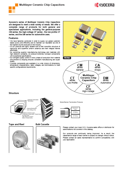
Pb Free
RoHS Compliant
series General
CM
series Arrays
CA
series Low Profile
CT
Multilayer Ceramic Chip Capacitors
series High-Voltage
series Automotive
DM
CF
Structure
Bulk Cassette
Size 05 105 21 EIA CODE 0402 0603 0805 EIAJ CODE 1005 1608 2012 L 1.00.05 1.60.07 2.00.1 W 0.50.05 0.80.07 1.250.1 T 0.50.05 0.80.07 1.250.1 P min. 0.15 0.20 0.20 max. 0.35 0.60 0.75 P to P min. 0.30 0.50 0.70
CAPACITANCE CODE
Capacitance expressed in pF. 2 significant digits plus number of zeros. For Values 10pF, Letter R denotes decimal point, eg. 100000pF 104 1.5pF 1R5 0.1F 104 0.5pF R50 4700pF 472 100F 107
CM CF CT DM General Purpose High Voltage Low Profile Automotive CA Capacitor Arrays
CM
21
X7R
104
K
多层陶瓷电容器MLCC物质安全资料表MSDS
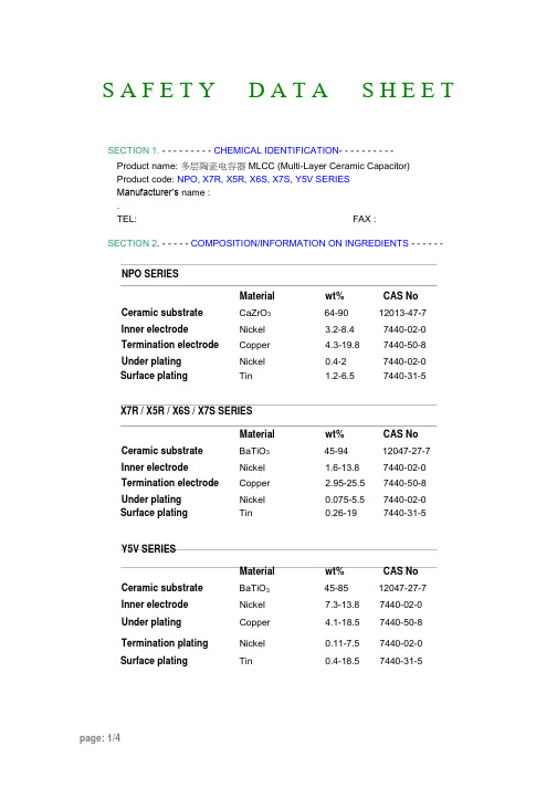
S A F E T Y D A T A S H E E TSECTION 1. - - - - - - - - - CHEMICAL IDENTIFICATION- - - - - - - - - -Product name: 多层陶瓷电容器MLCC (Multi-Layer Ceramic Capacitor)Product code: NPO, X7R, X5R, X6S, X7S, Y5V SERIESManufacturer’s name :.TEL: FAX :SECTION 2. - - - - - COMPOSITION/INFORMATION ON INGREDIENTS - - - - - - NPO SERIESMaterial wt% CAS No Ceramic substrate CaZrO3 64-90 12013-47-7Inner electrode Nickel 3.2-8.4 7440-02-0Termination electrode Copper 4.3-19.8 7440-50-8Under plating Nickel 0.4-2 7440-02-0Surface plating Tin 1.2-6.5 7440-31-5X7R / X5R / X6S / X7S SERIESMaterial wt% CAS No Ceramic substrate BaTiO3 45-94 12047-27-7Inner electrode Nickel 1.6-13.8 7440-02-0Termination electrode Copper 2.95-25.5 7440-50-8Under plating Nickel 0.075-5.5 7440-02-0Surface plating Tin 0.26-19 7440-31-5Y5V SERIESMaterial wt% CAS No Ceramic substrate BaTiO3 45-85 12047-27-7Inner electrode Nickel 7.3-13.8 7440-02-0Under plating Copper 4.1-18.5 7440-50-8Termination plating Nickel 0.11-7.5 7440-02-0Surface plating Tin 0.4-18.5 7440-31-5SECTION 3. - - - - - - - - - - HAZARDS IDENTIFICATION - - - - - - - - -Hazardous product for human health if swallowedSECTION 4. - - - - - - - - - - FIRST-AID MEASURES- - - - - - - - - - -Main effect : Risk of stomachacheEye contact : No irritation in human.Skin contact : No irritation in human.Ingestion : If swallowed, wash out mouth with water provided person is conscious.First aid : Consult with a physician in all cases.and take to hospital.SECTION 5. - - - - - - - - - FIRE FIGHTING MEASURES - - - - - - - - - - Common extinguishing means : In case of fire in close proximity,all means ofextinguishing are acceptable,e.g. foam,dry chemical,carbon dioxide,water.Inappropriate extinguishing means : No restrictionSpecific hazards : Non-combustible if temperature is lower than 1200 degree C.Protective measure in case of intervention : The product does not require any apecialprecautionExtinguishing instruction : Keep person removing from an upwind of fire.SECTION 6. - - - - - - - - ACCIDENTAL RELEASE MEASURES- - - - - - - - - Sweep up, place in a bag and collect for waste disposal.Prevent discharge into the environment(sewers,river,soil,- - - )SECTION 7. - - - - - - - - - - HANDLING AND STORAGE- - - - - - - - - - - Handling : Keep in a above environment , and original packing ,closed to befree of chlorine and bromide material contaminant .Storage : Keep storage place temperature from 20 to 40 degree C,humidity from45 to 75% RH .SECTION 8. - - - - - - EXPOSURE CONTROLS/PERSONAL PROTECTION- - - -Engineering control : Premises ventilationAuthorized limit values : Not applicableRespiratory protection : Not applicableHand protection : Not applicable Eyeprotection : Not applicable Skinprotection : Not applicable Otherprecaution : Not applicableSECTION 9. - - - - - - - PHYSICAL AND CHEMICAL PROPERTIES - - - - - - - Physical state : SolidAppearance : Gray brown / Silver metalOrder : NonePH value : Not applicableDecomposition temperature : Not applicableFlash point : Not applicableBoiling point : Not applicableMelting point : About 1200 degree CFlammable limits(LEL) : Not applicableFlammable limits(UEL) : Not applicableThe energy storage capacity of watt-hours equal or less than 0.3WhSECTION 10. - - - - - - - - -STABILITY AND REACTIVITY - - - - - - - - - Stability : Stable on normal temperature and pressureCondition to avoid : High temperature and humidityHazardous reaction with : Not applicableHazardous decomposition Products : Not applicableSECTION 11. - - - - - - - - - TOXICOLOGICAL INFORMATION - - - - - - - - Acute effects : Not applicableToxicity : Not traceableSECTION 12. - - - - - - - - - ECOLOGICAL INFORMATION - - - - - - - - - - Biological oxygen demand : Not applicableChemical oxygen demand : Not applicableBiological /Chemical oxygen demand ratio : Not applicableBiochemical factor : Not applicableEcotoxicity : Not applicableSECTION 13. - - - - - - - - - DISPOSAL CONSIDERATIONS - - - - - - - - - Installated or dump in a incinerator equipped in accordance with all federal, state , local and national environmental regulations.SECTION 14. - - - - - - - - - - TRANSPORT INFORMATION - - - - - - - - - No classification assigned.Not subject to Transport-regulation Dangerous Substances under IATA Dangerous Goods Regulations.SECTION 15. - - - - - - - - - REGULATORY INFORMATION - - - - - - - - - - Designation according to Sony SS-00259 ,EU WEEE/ROHS and customer ’s related standard.No classification assigned.SECTION 16. - - - - - - - - - - OTHER INFORMATION- - - - - - - - - - - - These data are based on our present knowledge.However,they shall not constitute a guarantee for any specific product feature and shall not establish a legally valid contractual relationship.。
mlcc的温度系数
mlcc的温度系数MLCC温度系数(Temperature Coefficient of MLCC)介绍:多层陶瓷电容器(MLCC)是一种常见的电子元件,广泛应用于电子产品中。
温度系数是衡量MLCC性能的重要指标之一。
本文将详细介绍MLCC温度系数的概念、计算方法以及其对电容器性能的影响。
一、MLCC温度系数的概念温度系数是指在一定温度范围内,电容器电容值与温度变化之间的关系。
温度系数通常用ppm/℃(百万分之一/摄氏度)来表示。
正温度系数表示电容值随温度的升高而增加,负温度系数则表示电容值随温度的升高而减小。
二、MLCC温度系数的计算方法MLCC温度系数的计算方法一般采用下述公式:温度系数 = (C2 - C1) / (C1 * ΔT) * 10^6其中,C1为参考温度下的电容值,C2为目标温度下的电容值,ΔT 为目标温度与参考温度之间的温度差。
三、MLCC温度系数的影响因素1. 材料特性:MLCC的温度系数与材料的选择有关。
常用的材料有C0G、X7R、Y5V等,它们具有不同的温度系数范围。
2. 制造工艺:制造工艺的不同也会对MLCC的温度系数产生影响。
例如,不同的烧结温度和冷却速率会导致材料结构的变化,从而影响电容值随温度变化的程度。
3. 封装方式:MLCC的封装方式也会对温度系数产生影响。
封装方式不同,电容器内部的结构也不同,从而导致温度系数的差异。
四、MLCC温度系数的应用1. 温度补偿电路:由于MLCC的温度系数不同,可以通过组合不同温度系数的电容器来实现温度补偿电路。
这样可以在不同温度下保持电容值的稳定性。
2. 温度传感器:利用MLCC的温度系数,可以设计出用于测量温度的传感器。
通过测量电容值的变化,可以推算出环境温度。
五、MLCC温度系数的注意事项1. 温度系数的选择:在实际应用中,根据具体需求选择合适的温度系数,以保证电容器在工作温度范围内的稳定性。
2. 温度系数与精度的关系:温度系数越小,电容器的稳定性越高。
- 1、下载文档前请自行甄别文档内容的完整性,平台不提供额外的编辑、内容补充、找答案等附加服务。
- 2、"仅部分预览"的文档,不可在线预览部分如存在完整性等问题,可反馈申请退款(可完整预览的文档不适用该条件!)。
- 3、如文档侵犯您的权益,请联系客服反馈,我们会尽快为您处理(人工客服工作时间:9:00-18:30)。
= 1 - lx+t lx
q n m x
=
p q n x m x+n
=
p - p n x n+m x
=
l - l x+n
x+n+m
lx
=
dm x+n lx
·d dt
pt x
= - t m px x+t
( ) ( ) ò d ( ) dt
qt x
=
t
m px x+t
· mx+t
=
-S¢ x + t S x+t
( ) ( ) å( ) Õ for Var ex
use E éëK
X
2ù û
=
¥ k =1
n-1
2k -1
k
px
·
pn x
=
p p p K p x x+1 x+2
x +n -1
=
px+k
k=0
for
continuous
to
discrete
estimate
æçè
o
e
® ex
ö÷ø using
linear
LIFE TABLES
Memorize
t
¥
¥
for Uniform éë0,wùû Þ lx = w - x · qt x = 1 - t px · dt x = lx qt x = lx - lx+t = ò lx+wmx+wdw · Tx = ò lwdw = ò lx t pxdt
0
x
0
( ) ( ) o
k =1
o
o
= ex:n + n px ex+n
( ) ( ) ( ) ¥
å ex = E ëéK X ûù = k=1 k px = px + 2 px 1+ ex+2 = px + 2 px + 3 px 1 + ex+3 = px + 2 px + 3 px + 4 px + 5 px + K¥
SURVIVAL
Memorize
x
x
ò ò ( ) ( ) ( ) ( ) ( ) ( ) m
x
:m
x
¥
> 0 and ò m 0
x
dx = ¥ ·S
x
- l(u )du
- m (t )dt
= e-L(x) = e 0
=e 0
Ûm
x
= - d ln S dx
x
x+t
t
px
=
S (x + t) S (x)
A2 1 , Ax:n x:n
n Ax , n A x
A , Ax:n x:n
A 1 º n Ex
x:n
INSURANCE
De Moivre
Ex:w = 95, x = 25,n =15,i = .03
a
a
( ) w-xi = 70 .03 = 0.4160
w - x 70
aw-x (1+i)2 -1
d
Ax
=
iAxContinuous=
i d
Discrete
Û
d
( Continuous ) =i ( Discrete )
F:\SOA & Exams\MLC\Study Sheets\study sheet 19.docx
Symbols
Ax , Ax
2
2 Ax , Ax
1
A1 , Ax:n x: n 21
º m(x) =
-
d dx
lx
lx
· notation convention:
m ( x + t ) º mx+t
( ( ) ) t px + qt x
=1Û
pt x
= 1- t qx · t px
=
lx+t lx
=
l0Sx x + t l0Sx x
· t qx
= lx - lx+t lx
=
dt x lx
t px =
survival function for T ( X ) · f (t ) = t m px x+t = t px mx (t ) =
fx (x + t Sx (x)
)
,
x
is
constant
hazard
function
® l(x) =
m (x) =
f (x) S (x)
·
f
(x) =
o
·e
=
ex
+
1 2
· lx+t
=
1-t
lx +
t
lx+1
Û
qs x+t
=
sqx 1- tqx
,0 £
s+t
£1
( ) ( ) ( ) Constant Force Þ mx+t = m · t px =
px
t = e-mt · Hyperbolic Þ mx+t
= 1-
qx 1-t
qx
·
qs x+t
Makeham: m ( x) = A + Bcx for x > 0, B > 0, c > 1, A > -B « A = 0 Þ Gompertz
Weibull: m ( x) = kxnfor x ³ 0, k > 0, n > -1
x+n
x+n
n
ò Sx ( y ) mx ( y ) dy ( ) ò f y dy ò t px mx+tdt
®
lx+0.25
=
0.25
px lx
( ) P éëK
X
= k ùû =
p q k x x+k
=
p - p k x k+1 x
=t
qx
=
dx+k lx
·
central rate of failure ®
m n x
=
dn x Ln x
Principles
S (x) =
lx l0
Û lx
= l0S ( x) · mx
1
= Ax:n + A 1
0
0
n
x:n
x:n
( ) Exponential Û Constant Force Þ Ax =
m
2
· Ax =
m
1
·Ax:n =
m
m +d
m + 2d
m +d
1 - e-n(m+d )
· A 1 º E n x = e-n(m+d )
x:n
ò ( ) ( ) 2
Ax
=
¥
e-2d t
Ax
=
1 a
w - x w-x
Û
A x:n
=
1 a
w-x n
Generalized
De
Moivre
Þ
lx
=
(w
-
x )a
o
· ex
=
(w
a
- x)
+1
Percentiles
® tp
=
- ln m
p
®
Zp
=
e-d t p
n
· òte-dtdt 0
=
an
- ne-nd d
Principles
ò ( ) 2 1
a = 70 .0609
=
1
1- 1 1.03140
= 0.2308
w-x
70 70 1.032 -1
a
a
( ) ni = 15 .03 = 0.1705
n
n
n
ex:n = ò S t dt = ò t pxdt = ò t t pxmx+t dt + n n px · ex = px 1+ ex+1 · Constant Force, mx = m Þ t px = e-mt
0
0
0
Uniform Û UDD
Û
"Linear Interpolation" Þ mx+t
S (x)m (x)· mt
º
m (t)· L(x) =
x
ò l (u )du
0
=
x
ò m (t) dt
0
( ) P (T ( x) > t ) = S (t ) = P X > x + t½X > x = 1- F (t )
( ) ( ) S ( x + t )
qt x = 1 - S ( x) = P
·t
px
ò- m(w)dw
=e x
where m ( x) =
-S '(x) S (x)
=
f (x) o S (x) ·ex
¥
=ò 0
S
x(
Sx
x
(
+t
x)
)
dt
¥
=ò x
Sx Sx
(t ) (x)
dt
Uniform