STM-125x型手动脱模器
电动脱模器的操作方法
电动脱模器的操作方法电动脱模器是一种用于模具中的脱模操作的设备。
它通常用于生产中需要更高效、更便捷的脱模操作。
在使用电动脱模器时,必须注意正确的操作方法和安全措施。
电动脱模器的结构电动脱模器主要由底座、支架、气缸、打孔器、脱模角等几个部分组成。
底座上有一个支架,安装有气缸和打孔器。
脱模角安装在打孔器下方,可以进行上下调节。
电动脱模器通常还有一个电控箱来控制气缸的动作。
电动脱模器的准备在使用电动脱模器之前,需要进行一系列的准备工作。
1.确认脱模角的适配性。
脱模角应该与模具的形状和尺寸相匹配,否则会导致脱模操作不成功或损坏模具。
2.检查气源和气路。
要确保气源和气路在良好的状态下,以确保气动设备能正常工作。
3.检查脱模角是否固定。
确保脱模角的安装和固定,以避免它在工作时脱落。
4.检查操作面板。
检查电动脱模器上的操作面板和控制台是否正常运行。
如果有任何问题,应该立即修理或更换。
电动脱模器的操作根据电动脱模器的操作步骤,可以保障脱模操作可以顺利实施1.打开电源。
打开电源,启动电动脱模器。
如果需要调整速度,可以在面板上进行相应的调整。
2.调整脱模角位置。
根据需要调整脱模角的位置,使其与模具相适应。
如果需要调整角度,可以进行相应的调整。
3.放置模具。
将需要脱模的模具放置在电动脱模器的工作台上,约束模具以避免移动。
4.操作电动脱模器。
按下面板上的按钮控制电动脱模器的动作。
在升降前应该设定卡死,同时应该在操作过程中注意观察脱模角的位置和与模具的接触情况,以便及时停止操作。
5.脱模角的操作。
当脱模角接触到模具后,会在几秒钟内将其推出模具。
此时应该及时停止电动脱模器的工作,以避免损坏模具。
6.关闭电源。
脱模完成后关闭电源。
注意事项在使用电动脱模器时,还需要注意以下事项。
1.安全使用必须戴上必要的安全装备,如手套和护目镜等,以免发生意外伤害。
2.操作环境保持操作环境干净、整洁并且保持通风,以确保操作人员的健康和安全。
3.定期保养定期对电动脱模器进行检查和保养,以确保设备的正常运行。
柯达 INDUSTREX MX125 薄膜说明书
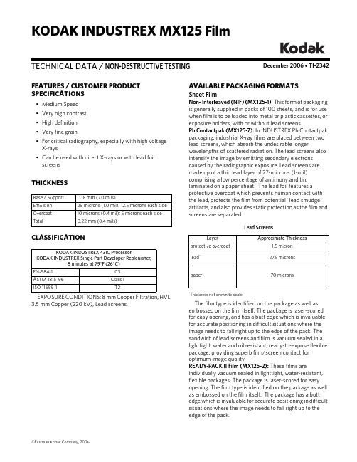
December 2006 • TI-2342TECHNICAL DATA / NON-DESTRUCTIVE TESTINGKODAK INDUSTREX MX125 FilmFEATURES / CUSTOMER PRODUCT SPECIFICATIONS•Medium Speed •Very high contrast •High definition •Very fine grain•For critical radiography, especially with high voltage X-rays •Can be used with direct X-rays or with lead foil screensTHICKNESSCLASSIFICATIONEXPOSURE CONDITIONS: 8 mm Copper Filtration, HVL 3.5 mm Copper (220 kV), Lead screens.Base / Support 0.18 mm (7.0 mils)Emulsion 25 microns (1.0 mil); 12.5 microns each side Overcoat 10 microns (0.4 mil); 5 microns each side T otal0.22 mm (8.4 mils)KODAK INDUSTREX 43IC ProcessorKODAK INDUSTREX Single Part Developer Replenisher,8 minutes at 79°F (26°C)EN-584-1C3ASTM 1815-96Class I ISO 11699-1T2AVAILABLE PACKAGING FORMATSSheet FilmNon- Interleaved (NIF) (MX125-1): This form of packaging is generally supplied in packs of 100 sheets, and is for use when film is to be loaded into metal or plastic cassettes, or exposure holders, with or without lead screens.Pb Contactpak (MX125-7): In INDUSTREX Pb Contactpak packaging, industrial X-ray films are placed between two lead screens, which absorb the undesirable longerwavelengths of scattered radiation. The lead screens also intensify the image by emitting secondary electrons caused by the radiographic exposure. Lead screens are made up of a thin lead layer of 27-microns (1-mil) comprising a low percentage of antimony and tin, laminated on a paper sheet. The lead foil features a protective overcoat which prevents human contact with the lead, protects the film from potential "lead smudge" artifacts, and also provides static protection as the film and screens are separated.Lead Screens*Thickness not drawn to scale.The film type is identified on the package as well as embossed on the film itself. The package is laser-scored for easy opening, and has a butt edge which is invaluable for accurate positioning in difficult situations where the image needs to fall right up to the edge of the pack. The sandwich of lead screens and film is vacuum sealed in a lighttight, water and oil resistant, ready-to-expose flexible package, providing superb film/screen contact for optimum image quality.READY-PACK II Film (MX125-2): These films areindividually vacuum sealed in lighttight, water-resistant, flexible packages. The package is laser-scored for easy opening. The film type is identified on the package as well as embossed on the film itself. The package has a butt edge which is invaluable for accurate positioning in difficult situations where the image needs to fall right up to the edge of the pack.LayerApproximate Thicknessprotective overcoat1.5 micron lead *27.5 micronspaper *70 micronsRoll FilmREADY-PACK (MX125-381): The film is supplied in a long, lighttight roll sandwiched between two yellow-black paper polyethylene layers. The rolls are of 60- or 100-metre lengths in a variety of widths. The film is provided in a dispenser box and is cut to length by the user in a darkroom.LEAD PACK (MX125-382): The film is supplied sandwiched between two 27-micron thick lead screens inside a long, lighttight paper and polyethylene sleeve. The rolls are 100 metres long and are cut to length by the user in a darkroom.NIF bulk roll (MX125-359): The film is supplied on a cardboard core in rolls 150 metres long in three widths: 60 mm, 70 mm and 100 mm. The film must be loaded into a cassette in a darkroom.SAFELIGHT RECOMMENDATIONSUse a KODAK LED Safelight (660 nm red) or a red safelight filter (i.e. KODAK 1, 1A, or 2 Safelight Filter) in a suitable safelight lamp equipped with a 15-watt bulb. Keep the film at least 4 feet (1.2 metres) from the safelight.Note: Other safelight filters (i.e. KODAK 8 and GBX-2 Safelight Filter) which block radiation at 550nm and shorter wavelengths are also suitable for use. STORAGE AND HANDLINGHandle film carefully to avoid physical strains such as pressure, creasing, or buckling.It is important to realize that meeting the chemical and physical requirements does not by itself ensure that records will not deteriorate. It is essential to provide proper storage conditions. ASTM E 1254 gives details of storage conditions. ISO 18911 and ISO 18902 give, for processed films, recommended storage conditions and specifications for the respective enclosure materials.Unexposed50 to 70°F (10 to 21°C), 30 to 50% RH. Properly shield from x-rays, gamma rays, or other penetrating radiation. ExposedKeep cool, dry, and properly shielded from penetrating radiation. Process as soon as possible after exposure. Processed60 to 80°F (15 to 27°C), 30 to 50% RH.RELATIVE EXPOSUREEXPOSURE CONDITIONS 8mm Copper Filtration, HVL 3.5 mm Copper (220kv), Lead screens.* MX125 Film in 8 min 79°F (26°C) cycle is assigned a relative exposure of 1.00.RELATIVE EXPOSURE FOR VARIOUS ENERGY LEVELSFor each exposure condition, MX125 Film, in 8 minute 79°F (26°C) cycle, is assigned a relative exposure of 1.0.* In accordance with ISO 7004 standard. Without lead screens† In accordance with ISO 7004 standard - EN 584-1 Lead screens‡ 8 mm Copper filtration. 100/200 microns lead screens§ 100/200 microns lead screensAUTOMATIC PROCESSINGNotice: Observe precautionary information on product labels and Material Safety Data Sheets.See Kodak publication TI-2621, Processing KODAK INDUSTREX Films, for additional information on automatic processing.EXPOSURE CONDITIONS: 200/220 kV, ISO/ANSI/EN Conditions, KODAK INDUSTREX ChemicalsFilm Characteristics (Sensitometric)* Contrast calculated between net densities of 1.5 and 3.5.KODAKINDUSTREX FilmsKODAK INDUSTREX ProcessorKODAK INDUSTREX Chemicals8 min 79°F (26°C)DR50 2.6M100 1.5MX125* 1.0T2000.6AA4000.4HS8000.2INDUSTREXFilmsISO 120*EN 220†Iridium‡Cobalt§DR50 3.0 2.6 2.9 2.7M100 1.4 1.5 1.7 1.9MX125 1.0 1.0 1.0 1.0T2000.60.60.60.6AA4000.40.40.30.3HS800—0.2——KODAK INDUSTREXProcessor / CycleBase + Fog Contrast*M43IC, 8 min 79°F (26°C)0.20 5.15M43IC, 5 min 86°F (30°C)0.20 5.05M35, 8 min 86°F (30°C)0.20 4.9Recommended Replenishment RatesThe consistency of the radiographic quality is related to the accurate adjustment of the replenishment rate.Replenishment should maintain the chemical equilibrium, replacing the components used by the film.* For optimum archivability, a 10% increase in fixer replenishment rate may bedesirable.Washing and DryingWashing: Follow the processor manufacturer'srecommendation for wash flow rate, or adjust flow to achieve the equivalent of the wash tank capacity every five minutes, or twelve tank volumes per hour. Insufficient wash flow can adversely affect the life expectancy of processed radiographs. Wash flow rate should be increased if chemical spot tests or other analyticalmethods reveal a high level of retained chemicals in the processed film. For best results, the wash tank should be drained daily and left empty when not in use.Drying: Follow the processor manufacturer'srecommendation for dryer settings. In general, the dryer should be set to a temperature slightly above (3°C/5°F) the lowest temperature required to eliminate any signs of tackiness in films exiting the dryer.MANUAL PROCESSINGNotice: Observe precautionary information on product labels and Material Safety Data Sheets.See Kodak publication TI-2643, Guide to Manual Processing of NDT Films , for additional information on manual processing.Film Characteristics (Sensitometric)* Contrast calculated between net densities of 1.5 and 3.5.Solution Replenishment Volumeper 35 x 43 cm (14 x 17 inch) sheetper m 2Developer 100 mL 665 mL Fixer180 mL *1200 mLDevelopment Conditions Base + Fog Contrast *5 min 68°F (20°C)0.19 5.03 min 75°F (24°C)0.195.1DevelopmentDevelop with rack and tank, using properly replenished solutions.•Remove film and hanger 5 seconds before end of development. DO NOT ALLOW EXCESS DEVELOPER TO DRAIN BACK INTO THE TANK. Normally this will carry out the proper amount of solution to permit correct replenishment.•Use floating covers on developer tanks to reduce oxidation and evaporation; store developer replenisher in a closed container. •Fill the developer and fixer tank to its original level each morning with developer or fixer replenisher solution (topping off).•Discard solution after adding two tank volumes of replenisher to tank, or at least once a month, and refill with fresh solution.Stop, Fix, Wash and Dry StepsStop baths check development, prevent most spots or streaks, and prolong the life of the fixing bath.Immerse the film in fixer for 3 to 6 minutes , agitating for 5 seconds every 30 seconds . Film should remain in fixer for twice the time it takes to "clear" it (when the milky look disappears). Never fix film for less than 3 minutes.KODAK Hypo Clearing Agent may be used following the fixer to reduce washing time and conserve water. First rinse films in running water for 30 seconds, the use Hypo Clearing Agent for 1 to 2 minutes, followed by a final running water wash for 5 minutes.T emperature RecommendedT ime(Minutes)Agitation KODAK INDUSTREX Single Part Developer Replenisher68°F (20°C)72°F (22°C)75°F (24°C)79°F (26°C)5432Intermittent (5 seconds every 30 seconds)T emperatureRecommendedT ime Agitation KODAK Indicator Stop Bath, or acetic acid (diluted to 3.5%) solution 60 to 85°F 16 to 30°C30 to 60 secondsContinuous, ModerateKODAK Rapid Fixer, KODAK INDUSTREX Manual Fixer, or KODAKINDUSTREX LO Fixer and Replenisher 60 to 85°F 16 to 30°C3 to 6 minutes, or twice the clearing timeVigorous for 15 seconds, then intermittent (5 sec every 30 sec)Running water wash(8 volumechanges per hour)60 to 85°F 16 to 30°C 10 to 30MinutesKODAK INDUSTREX MX125 FilmAerial and Industrial MarketsEASTMAN KODAK COMPANY • ROCHESTER, NY 14650-0505Revised 12-06Printed in U.S.A.KODAK INDUSTREX MX125 Film KODAK Publication No. TI-2342NOTICE: While the sensitometric data in this publication are typical of production coatings, they do notrepresent standards which must be met by Kodak. Varying storage, exposure, and processing conditions will affect results. The company reserves the right to change and improve product characteristics at any time.To minimize water spots and drying marks, use KODAK PHOTO-FLO Solution after washing.Dry in a dust-free area at room temperature or in a suitable drying cabinet. Temperature not to exceed 120°F (50°C).Recommended Replenishment RatesMaintain chemical activity and solution level in the developer tank by adding 100 ml (3.38 fluid ounces) of replenisher according to instructions for each 14 x 17-inch (35 x 43 cm) film processed. Stir vigorously after each addition. Replenish the fixer tank at the rate of 180 mL (6 fluid ounces) per 35 x 43 cm (14 x 17 in) sheet of film processed.CURVESCharacteristic Curves, Manual ProcessingCharacteristic Curves, Machine ProcessingKodak, Industrex, Lead Pack, Ready-Pack, and Photo-Flo are trademarks.。
移动模架计算书
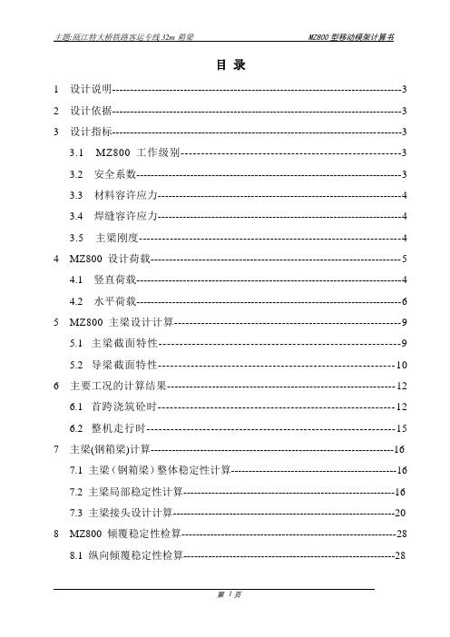
目录1设计说明---------------------------------------------------------------------------------3 2设计依据---------------------------------------------------------------------------------3 3设计指标---------------------------------------------------------------------------------33.1 MZ800工作级别------------------------------------------------------33.2 安全系数--------------------------------------------------------------------------33.3 材料容许应力--------------------------------------------------------------------43.4 焊缝容许应力--------------------------------------------------------------------43.5 主梁刚度--------------------------------------------------------------------4 4MZ800设计荷载--------------------------------------------------------------------54.1 竖直荷载--------------------------------------------------------------------------44.2 水平荷载--------------------------------------------------------------------------6 5MZ800主梁设计计算-----------------------------------------------------------95.1主梁截面特性----------------------------------------------------------95.2导梁截面特性----------------------------------------------------------10 6主要工况的计算结果-------------------------------------------------------------126.1首跨浇筑砼时-----------------------------------------------------------126.2整机走行时--------------------------------------------------------------157 主梁(钢箱梁)计算---------------------------------------------------------------------167.1 主梁(钢箱梁)整体稳定性计算-----------------------------------------------167.2 主梁局部稳定性计算------------------------------------------------------------167.3 主梁接头设计计算---------------------------------------------------------------208 MZ800倾覆稳定性检算------------------------------------------------------------288.1 纵向倾覆稳定性检算------------------------------------------------------------288.2 横向倾覆稳定性检算------------------------------------------------------------289 MZ800纵横移结构设计计算-----------------------------------------------391 设计说明本移动模架是利用原江西省GZ20号公路桃木岭高架桥MZ850型移动模架造桥机改制,用于施工瓯江特大桥铁路客运专线32m简支箱梁。
脱模器操作规程
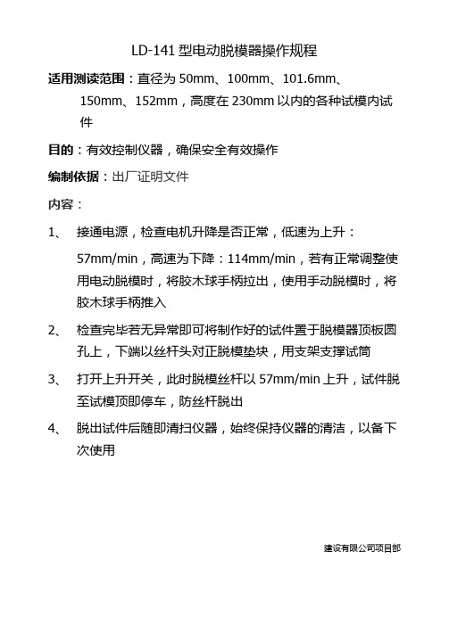
LD-141型电动脱模器操作规程
适用测读范围:直径为50mm、100mm、101.6mm、150mm、152mm,高度在230mm以内的各种试模内试
件
目的:有效控制仪器,确保安全有效操作
编制依据:出厂证明文件
内容:
1、接通电源,检查电机升降是否正常,低速为上升:
57mm/min,高速为下降:114mm/min,若有正常调整使用电动脱模时,将胶木球手柄拉出,使用手动脱模时,将胶木球手柄推入
2、检查完毕若无异常即可将制作好的试件置于脱模器顶板圆
孔上,下端以丝杆头对正脱模垫块,用支架支撑试筒
3、打开上升开关,此时脱模丝杆以57mm/min上升,试件脱
至试模顶即停车,防丝杆脱出
4、脱出试件后随即清扫仪器,始终保持仪器的清洁,以备下
次使用
建设有限公司项目部。
锈纹抗腐铁丝推撒器THS125说明书

INSTRUCTION MANUAL125LB (56.8kgs)PUSH SPREADERModel No: THS125 -- Product No: 1938137001ASSEMBLY REQUIREDSAVE THESE INSTRUCTIONSSPARES & SUPPORT: 01793 333212Please read & understand this manual, paying attention to the safety instructions, before use. The manufacturer reserves the right to change the product specification and livery according tocontinued product improvements.Images used are for illustration purposes only01/02/2017CONTENTSSPECIFICATIONIMPORTANT INFORMATIONGENERAL SAFETY INSTRUCTIONSCOMPONENTSASSEMBLYADJUSTMENTSMAINTENANCEOPERATIONRATE SETTINGSPARTS DIAGRAMPARTS LISTWARRANTYNOTESASSEMBLY IS REQUIREDThis product requires assembly before use. See the “Assembly” section for instructions. Please check that all parts required for the assembly of this spreader are included. If for any reason, you believe a part for the assembly is missing or damaged, please contact us.If you require any assistance with regards to the contents or operation ofyour machine, please contact us:TEL: 01793 333212EMAIL:************************************.uk(MON – FRI 8.00AM TO 5.30PM EXCL. BANK HOLIDAYS)DO NOT USE WITH ROCK SALT.Using rock salt in this spreader will damage the mechanism and shorten the life of the product. Refined ice melting salt can be used but the user should be aware that this is not a specialised salt spreader and using salt may corrode the spreader and reduce the life of the machine.Clean the spreader thoroughly after using refined de-icing salt.THSSPECIFICATIONSThe manufacturer reserves the right to change the product specification and livery according to continued product improvements.IMPORTANT INFORMATIONINTENDED USEThe product is intended for spreading granular material for domestic gardens. This product is not intended for commercial use. Generally acknowledged accident prevention regulations and enclosed safety instructions must be observed.Only perform work described in these instructions for use, any other use is incorrect. The manufacturer will not assume responsibility for damage resulting from such use. GENERAL SAFETY INSTRUCTIONSRead and understand the owner’s manual and labels affixed to the product. Learn its application and limitations as well as the specific potential hazards. Retain these instructions for future reference. The operator is responsible for following the warnings & instructions in this manual and on the product.STAY ALERTDo not operate the machine while under the influence of drugs, alcohol, or any medication that could affect your ability to use it properly. Do not use this machine when you are tired or distracted from the job at hand. Be aware of what you are doing at all times. Use common sense.AVOID DANGEROUS CONDITIONSMake sure there is adequate surrounding workspace. Cluttered areas invite injuries. Keep your work area clean with sufficient light. Keep the area around the machine clear of obstructions, grease, oil, rubbish & other debris which could cause persons to fall onto moving parts. INSPECT YOUR MACHINECheck all bolts, nuts & screws for tightness before each use, especially those securing guards & drive mechanisms. Vibration during use, may cause these to loosen.Replace damaged, missing or failed parts before using.Warning labels carry important information. Replace any missing or damaged warning labels.CRUSH AND CUT HAZARDSAlways keep your hands and feet clear from moving parts while operating the equipment. Always keep the work area clean and clear when operating.CONDITIONSWe recommend the machine is not used during winds. This may affect the spreading pattern.DRESS PROPERLYDo not wear loose clothing, gloves, scarfs, neckties or jewellery (rings, wrist watches), which can be caught in moving parts.DO NOT OVERREACHKeep proper footing and balance at all times when using the machine. Never stand on the machine. Serious injury could occur if the machine is tipped or if the moving parts are unintentionally contacted. Do not store anything above or near the machine, where anyone might stand on the machine to reach them.AVOID INJURY FROM UNEXPECTED ACCIDENTKeep hands & feet out of the way of all moving parts. Do not place any part of your body or any tool e.g. in moving parts of the machine during operation.DO NOT FORCE TOOLAlways work within the rated capacity. Do not operate for a purpose for which it was not intended.MAINTAIN YOUR MACHINE WITH CARE Clean the machine immediately after use. Keep the machine clean to ensure it operates to its full & safest performance. When maintaining this machine, only the manufacturer’s original replacement parts should be used. The use of non-original manufacturer parts may invalidate your warranty.PROTECT THE ENVIRONMENTTake left over materials to an authorised collection points or follow the stipulations in the country where the machine is used. Do not discharge into drains, soil or water. STORE IDLE EQUIPMENTWhen not in use, the machine should be stored in a dry location. Keep the machine away from children and others not qualified to use it. OPERATION SPEEDDo not exceed 10mph, to avoid personal injury and/or equipment damage.TYRE INFLATIONBefore operating, make sure the tyres have the recommended pressure of 25 PSI (Do not exceed 25 PSI). We recommend the use of FOOT or HAND manual inflation devices only. This is a garden/domestic product, therefore extended use over abrasive surfaces (e.g. concrete, tarmac etc.) could cause premature wear on the tyres.SAFETY SYMBOLSSafety alert symbol. Used to alert you to potential personal injury hazards. Obey all safety messages that follow this symbol to avoid possible injury.DANGERIndicates an imminently hazardous situation which, if not avoided, will result in serious injury.WARNINGIndicates a potentially hazardous situation which, if not avoided, could result in serious injury.CAUTIONIndicates a potentially hazardous situation which, if not avoided, may result in minor or moderate injury.CAUTIONUsed without the safety alert symbol indicates a potentially hazardous situation which, if not avoided, may result in property damage.KNOW YOUR MACHINERead this owner’s manual before operating the equipment. Familiarize yourself with the location and function of the controls and features. Save this manual for future reference.123 6451.T-Handle –Pushes and moves the spreader easily.2.Flow Control –Controls the flow of material being spread3.Hopper –Do not exceed rated load capacity 125lb (56.8kgs).4.Tyre/Wheel –Do not exceed recommended inflation rated 25 PSI.5.Impeller - Evenly distributes material.6.Support Leg –Stabilizes load and spreader, when stationary.COMPONENTSNOTE: Parts Lists are supplied for information purposes only, not all parts are stocked individually & we recommend you contact our Spares Team on 01793 333212 for expert advice.ASSEMBLYRECOMMENDED TOOLS REQUIRED•Pliers•Adjustable Spanner•8mm Wrench•10mm Wrench•13mm Wrench•14mm WrenchSTEP 1 - Wheels•On the left side of the axle install a wheel bushing and wheel spacer onto the axle.•Slide a wheel over the axle.•Put a Ø16 flat washer over the axle, insert the cotter pin through the hole and secure by bending. •On the right side of the axle slide a wheel bushing and the wheel spacer onto the axle.•Put a wheel over the axle, line up the holes and insert the drive pin through sleeve and lock. •Put a Ø16 flat washer over the axle, insert the cotter pin through the hole and secureNOTE: Four additional flat washers are provided for adjusting the gap between the wheelsSTEP 2 – Support Leg•Position the support leg so the J-shaped end is pointing away from the wheel assembly. •Insert the M8x75 hex bolt through the top hole on the support leg and slide the spacer over the bolt end.•Take the support leg and insert the bolt through the upper cross bar on the mounting assembly and loosely tighten with the M8 lock nut.NOTE: Before tightening the bolt make sure the support leg flange and the lower cross bar holes line up.•Insert M6 x 40 hex bolt through the holes in the flange and cross bar. Use the Ø6 big flat washer and M6 lock nut.Cross BarFlangeSTEP 3 - Hopper•Lower the hopper over the mounting assembly, carefully line up the holes in the bottom of the hopper with the spindle in the mounting plate of the axle.•Use the M6 x 40 hex bolt and Ø6 flat washer to attach the hopper to the mounting assembly and secure with M6 lock nut.•Make sure the gear and pinion gear works smoothly. If not, adjust again until the gear and pinion gear swivel smoothly.•Tighten all the hardware on the shaft support plate and hopper.•Insert the R Pin through the top of the spindle.STEP 4 – Connecting Handle•Slide the handle tube into the top of the support leg and align the two fixing holes.•Insert M6x35 hex bolts through the two holes on the support leg and tighten with the Ø6 spring washer and M6 lock nut.•Insert M6x20 hex bolt through the hole in the side plate and tighten with Ø6 spring washer and M6 lock nut.STEP 5 – Solid Linkage•Connect the solid linkage through the bottom fix plate using the Ø8 flat washer and tighten with an M8 lock nut.•Connect the other end of the linkage to the flow control with an Ø8 flat washer and M8 lock nut. •Install the hopper screen in the bottom of the hopper.•Before using the spreader make sure all the hardware is tightened.•Use the rain cover as needed to protect material in the hopper or when spreader is being stored.ADJUSTMENTSSTEP 6When you have finished all the above steps, if the hole at the bottom of hopper cannot be closed and opened completely by using the handle you may need to the follow these additional steps. •The handle adjusts the spreader setting. When the handle is moved to “30”, the adjustable plate is fully open, when at “0”, it is fully closed.•Loosen the wing nut on the Bracket and move the adjustment lever handle up or down depending on the amount of material required. Pushing the handle down will release more material and pulling the handle up will stop the flow entirely.•Tighten the wing nut when the desired position is reached.To operate this spreader, push the handle to the lowest position (downwards). You may move the position of the Wing nut on the Gauge & Lever to adjust the space on the hole between the hopper and the adjustable plate as per your need when spreading.OPERATIONDANGERThe product must only be put into operation if no defects are found. It is crucial that any defective parts are replaced before the product is used again. Check the safety equipment and the safe condition of the product. Check all parts to make sure that they fit tightly. Check whether there are any visible defects: broken parts, cracks, etc.DANGER - DO NOT EXCEED MAXIMUM LOAD CAPACITY OF 125LBS (56.8KG)NOTE: ALWAYS MOVE OFF BEFORE OPENING THE FEED-GATE. ALWAYS CLOSE THE FEED-GATE BEFORE STOPPING.•Inspect your spreader before each use. Make sure the wheels turn easily, and the gearbox moves when the spreader is pushed. The hopper should be clean and free from cracks.•DO NOT use the spreader on windy days.•Before filling the hopper, ensure the feed-gate flow hole is closed, with the flow control lever at “0”. Always follow the spreading material manufacturer spreading rates.•The Spreader is designed to be pushed at 3 miles per hour – brisk walking pace. The rate of walking will affect the spread pattern and flow rate.•Move the Wing Nut attached to the stop bolt on the gauge to the relevant setting.•Start pushing the Spreader forward & pull the control lever back to the stop bolt, opening the feed-gate flow hole at the bottom of the hopper.•Every time you are ready to stop or turn back, close the flow control plate to stop dispersing the material and continue one more stride. This reduces waste and avoids damaging the lawn by oversaturating it with the product.•To maintain the same coverage when walking at a different speed, adjust the flow rate. Reduce the flow setting for slower speeds and increase the flow setting for higher speeds. Keep the impeller plate horizontal when operating the spreader. Tilting the spreader will result in uneven coverage.•If the Spreader does not spread evenly, ensure that the gearbox rotates the impellor clockwise. •Material which is stuck on the impellor blades will cause uneven spreading.•To stop spreading, push the gauge lever forward to close the feed-gate hole in the hopper. •Remove the agitator when using refined de-icing salt to reduce gearbox damage. Salt may corrode the machine and reduce its working life. DO NOT USE ROCK SALT.•If fertiliser is accidentally deposited too heavily in a small area, soak the area thoroughly with a garden hose or sprinkler to prevent burning the lawn.•When broadcasting weed control fertilisers, make sure the broadcast pattern does not hit evergreen trees, flowers or shrubs.•Always use the rain cover in wet weather conditions to keep the hopper contents dry.RATE SETTINGSOur spreaders are designed to spread dry, powdered or granulated materials thinly and evenly over reasonably smooth surfaces.•Ensure that the material is dry and free-running. If in doubt pass it through a sieve with 3mm mesh to remove lumps.•Set rate-setting dial to No 12.•Fill the hopper approximately 3/4 full.•Push the spreader forward and pull the control lever back to the Stop bolt. If the spread is uneven or inadequate, close the feed-gate and reset the dial to a higher number.Always move off BEFORE opening the feed-gate and close the gate BEFORE stopping.CAUTIONThe rate settings are guidelines only. Even branded materials may vary in grain size, humidity, density etc. If in any doubt choose a lower setting than that suggested or start at setting no. 12 and adjust as necessary, until an even spread is achieved.WARNINGDo not over apply spreading material. Follow the recommended coverage rate for each product. Over application will lead to damage and contamination. If spreading material accidentally deposits too heavily, soak the area thoroughly with a garden hose or sprinkler to prevent burning.CAUTIONDO NOT USE WITH ROCK SALT.Using rock salt in this spreader will damage the mechanism and shorten the life of the product. Refined ice melting salt can be used but the user should be aware that this is not a specialised salt spreader and using salt may corrode the spreader and reduce the life of the machine. Clean the spread thoroughly after using refined de-icing salt.CONSISTENT COVERAGETo ensure consistent coverage, ensure each broadcast pattern slightly overlaps the previous, as shown below. N.B. ALWAYS MOVE OFF BEFORE OPENING FEED-GATE.ALWAYS CLOSE FEED-GATE BEFORE STOPPINGMAINTENANCELUBRICATEMaintenance spray or multi-purpose grease can be applied to the wheel axle prior to long-term storage. Oiling is not necessary.GEARBOXApply multi-purpose grease to the gearbox cogs at the end of each use.CHECK TYRE INFLATIONPrior to using the Spreader, ensure the tyres are sufficiently inflated. We recommend the use of FOOT or HAND manual inflation devices only. Do not inflate above 25psi.CLEANINGAfter each use thoroughly wash the spreader and clean material out of the hopper.STORINGNever allow material to stay in the hopper for extended periods of time. Before storing, ensure that the spreader is clean and dry. Store indoors or in a protected area during severe weather in the winter months and direct sunlight.CHECK ALL NUTS, BOLTS AND FASTENINGPeriodically check all fastenings are tight & secure.NEVER EXCEED LOAD CAPACITYTo avoid damaging the spreader, never exceed the rated load capacity of 125LB (56.8kg).PARTS DIAGRAM – THS125 (1938137001)NOTE: Parts Lists are supplied for information purposes only, not all parts are stocked individually & we recommend you contact our Spares Team on 01793 333212 for expert advice.PARTS LIST – THS125 (1938137001)GJ HANDY & CO LTD USER WARRANTY POLICY Users Statement of WarrantyEach new machine is warranted against defective material or assembly of material under normal usage. The warranty applies to the original purchaser and covers faulty parts and the labour involved in replacing and repairing those parts, which are of original manufacture.Period of WarrantyAll Webb & Webb Pro machines plus Sanli engines.a) 2 years from the original date of sale to the first domestic user.b)90 days from the original date of sale to the professional/commercial user.c)90 days from the original date of sale when used for hire.d) A reduced warranty period of 90 days applies to those items which are subject to normalwear and tear (e.g. but not limited to wheels, tyres, cutter bars, cylinders, blades, belts,cables, grass bags, spark plugs).e)Engines as per the manufacturer’s warranty statement which will be supplied with themachine.f)90 days from the original date of purchase for Replacement Spare Parts (unless normal wear& tear component, which are covered for 30 days).g)All machines’ must be serviced within the first 12 months from the original date of purchaseto comply with the warranty, failure to do so will invalidate the 2nd year of the warranty.All Handy, Mowerland and Q-Garden products.a) 1 year from the original date of sale to the first domestic user.b)90 days from the original date of sale to the professional/commercial user.c)90 days from the original date of sale when used for hire.d) A reduced warranty period of 90 days applies to those items which are subject to normalwear and tear (e.g. but not limited to wheels, tyres, cutter bars, cylinders, bottom blades,belts, cables, collection bags, spark plugs).e)Engines as per the manufacturer’s warranty statement which will be supplied with themachine.f)90 days from the original date of purchase for Replacement Spare Parts (unless normal wear& tear component, which are covered for 30 days).All warranty repairs must be undertaken by an authorised service dealer. These dealers have been accredited by GJ Handy & Co Ltd and agree to only use genuine parts and follow our repair procedures.Version 4 10-16GJ HANDY & CO LTD USER WARRANTY POLICYNot covered by this warrantya)The warranty policy does not cover any depreciation or damages caused by ordinary wear,rusting or corrosion, lack of correct maintenance or operation, misuse, abuse, lack oftransportation or accident.b)The warranty policy does not cover any costs necessary for the standard periodicmaintenance services instructed by the operator’s man ual, or service parts replacementwhich would include oil, filters, tyres, belts, brake linings, fuses, blades, seals and otherservice parts unless it can be proven that the item has evidence of faulty manufacture.c)The warranty policy will not cover failure or damage caused as a result of parts oraccessories being modified without the written approval of GJ Handy & Co Ltd.d)The warranty policy will not cover the unit if non-genuine parts have been fitted and as aresult damage has occurred to the unit.e)The warranty policy is non-transferable and is only applicable to the original purchaser. Disclaimera)This warranty is only a remedy for defect of products. GJ Handy & Co Ltd will never warrantyin terms of the merchantability or the fitness for a particular purpose.b)No person is authorised to make any warranties, representations or promises, expressed orimplied, on behalf of GJ Handy & Co Ltd, or to modify the terms conditions or limitation ofthis warranty policy in any way.c)Neither GJ Handy & Co Ltd nor any company affiliated with GJ Handy & Co Ltd shall be liablein any event or manner whatsoever for incidental or consequential damages or injuries,including, but not limited to, loss of crops, loss of profit, out of pocket expenses or profits,rental of substitute equipment or other commercial losses.Generala)Most warrantable failures show up within the first few weeks of use. These failures areusually straightforward and warranty assessment is relatively easy.b)Failures relating to cutter decks and belts need careful investigation, as the cause may notalways be straightforward. Look for damage to blades and pulleys especially when the cutter belt or blade boss have snapped or cracked as this could be due to impact damage.c)Customers should always refer to the operator/instruction manual when any disputedproblem arises, you will find most areas covered within the manual.For spares or support of your handy product,please contact us:Tel: 01793 333212Email:************************************.uk (Mon – Fri 8.00am to 5.30pm excl. Bank Holidays) To see our range of garden machinery & equipment visit: Making gardening easier & affordable since 1938 Distributed by Handy Distribution, Murdock Road, Dorcan, Swindon, SN3 5HY。
塑件脱模机构设计

人工取出针点浇口凝料
塑料成型模具
利用斜孔(面)拉断针点浇口
此种结构最好用倒锥头或球头拉料杆,且分流道最好开 在定模板上,如开在动模板上则要用较长的中心顶杆。
Flash 动画
塑料成型模具
利用拉料杆拉断针点浇口
模具先从A面分型,距离由限位杆6确定;再从B面分型,距离 由(限位杆7减去限位杆6的限位距离)决定.最后完成主分型, 再顶出制品.
Flash 动画
二级脱模-气动式
塑料成型模具
塑料成型模具
二级脱模-弹簧式
Flash 动画
二级脱模-凸轮推杆式
塑料成型模具
用于第一级脱模距离较短的情况。注意凸轮的旋转角度 不能太大,以免合模发生自锁,使凸轮不能压回。
塑料成型模具
二级脱模-拉勾推杆式
Flash 动画
二级脱模-滑块式
塑料成型模具
带螺纹制品的脱模
利用硅橡胶螺纹型芯强制脱螺纹
塑料成型模具
开模时,在弹簧的作用下,先让出硅橡胶中的型芯以便于 桂橡胶螺纹型芯的向内收缩。为顺利地强制脱螺纹作好准 备。 硅橡胶螺纹型芯寿命低,用于小批量生产。
带螺纹制品的脱模 利用分瓣式可涨缩型芯脱螺纹
缺点是螺纹的内表面有拼合线痕迹。 也可成型其它的塑料件侧凹。
脱螺纹机构的设计计算
塑料成型模具
故要正确设计定模的分型距离l1,如果l1过 长,则型芯已旋出,而制品还未从型腔中退出。 如果l1太短,则会使制品完全从型腔中脱出时, 而还有几扣螺纹未旋出。 设还有n扣螺纹未旋出时,定模停止分型,此时 制品仍在型腔内。则有:n=H/(2iT-t) 其中H为 制品的高度。l1= N-n)(2iT-t)=2iNT-h-H 其中 =(N-n)(2iT-t)=2iNT-h-H h为制品的螺纹部分高度。总开模距L=l1+h+H =2iNT+5~10mm. 方轴与丝杆的相对运动距离为开模行程的一半, 故方轴长度L1=L/2+a 。a为配合部分长度(一 般取25mm)。
冲压设备脱模方法

冲压设备脱模方法
冲压设备脱模方法主要包括以下几种:
1. 使用模具抽出器:在冲压过程中,模具底部安装一个抽出器,通过该抽出器在冲压完成后迅速将成品从模具中抽出,使得成品完全脱离模具。
2. 涂抹脱模剂:在模具表面涂抹一层脱模剂,常用的脱模剂有脱模油、脱模蜡等。
脱模剂能够减小模具与工件之间的摩擦力,降低脱模力,从而实现工件的脱模。
3. 加热冲压:在冲压过程中,通过加热模具或工件来减小摩擦力,提高工件与模具之间的脱模性能。
常用的加热方式包括经过预热的模具和热冲压。
4. 增加脱模斜度:设计模具时,适当增加工件的脱模斜度,使工件在冲压完成后更容易从模具中脱离。
5. 使用薄膜脱模:在模具表面贴上一层薄膜,使工件能够在冲压完成后容易从模具上剥离。
不同的冲压工艺和工件要求会选择不同的脱模方法,通过合理的选择和应用,可以有效提高冲压过程中的脱模效果,提高生产效率。
电动液压脱模器用途 液压脱模器技术指标

电动液压脱模器用途液压脱模器技术指标电动液压脱模器用途:该仪器可用于直径为:50mm、100mm、101.6mm、150mm、152mm 高度为230mm以内的各种试模内试件脱模。
电动液压脱模器操作规程:▲使用前应检查电气系统,接地是否牢靠,熔丝是否有效等,确认无误后方可进行操作。
▲加油或换油后,必需排尽系统内空气,即先将升降杆臵于中心停止位臵,倒顺开关拨到中心停止位臵,然后接通电源,将倒顺开关向右拨到开机位臵,油泵开始工作;上提升降杆使升降活塞上升一段距离,察看有无卡滞等异常现象,如有,则立刻关机检查,排出故障;如无异常现象,应使活塞上升一段距离后再下降,如此往还几次,以排出油缸内的空气,并察看无异常现象时,将升降杆臵于中心停止位臵,即可待机使用。
▲使用前,应向油箱内加注6L液压油(打开后盖板加油),并检查各油管接头和紧固件是否松动,以防漏油影响使用;以后使用过程中,应依据使用情况,定期检查液压油干净与否,并每半年更换一次液压油,以防影响正常工作。
▲液压油规格应视温度不同选用:(1)当环境温度为15℃5℃时使用GB443—84N46(相当于30#液压油);(2)当环境温度为25℃5℃时使用GB443—84N68(相当于40#液压油)。
▲脱模时应先调整托盘高度,以符合不同试模要求,把带有试件的试模连同下压块一起放在托盘上,大致定位后,依据不同试模确定使用不同的脱模定位环(150或152的大试模不用定位环),注意此时定位必需精准无误。
▲试模定位后,上提升降杆开始脱模,注意察看脱模情况;当试件脱出定位环时立刻下压升降杆至中心停止位臵,使活塞停止上升。
▲认真取走脱出的试件,备试验用,下压升降杆至下降位臵,使活塞降下至托盘以下位臵即停,当心取走定位环、试模和下压块,以便下一个试件制模和脱模。
▲当全部试件脱模完成后,降下托盘,下压升降杆至下降位臵,使活塞降至工作台以下位臵即停,将倒顺开关向左拨到停机位臵,油泵停止工作,切断电源,清理好工作台和试模等,并将试模等涂拭防锈机油,以备下次使用。
模具快速装卸装置

模具快速装卸装置在现代工业生产中,模具的使用非常广泛,而模具的装卸效率对于生产效率和成本有着重要的影响。
为了满足快速生产的需求,模具快速装卸装置应运而生。
模具快速装卸装置是一种专门设计用于提高模具更换速度和便利性的设备。
它的主要作用是减少模具装卸过程中的时间和人力消耗,降低操作难度,提高生产的连续性和稳定性。
传统的模具装卸方式通常需要大量的人力和时间,而且操作过程较为复杂,容易出现安全事故。
例如,在没有专门的装卸装置时,工人可能需要使用吊车、叉车等设备来搬运模具,然后通过手动调整和固定来完成安装,这个过程不仅费时费力,还可能因为操作不当导致模具损坏或者人员受伤。
而模具快速装卸装置则有效地解决了这些问题。
它通常由以下几个主要部分组成:首先是定位系统。
这一系统能够确保模具在安装时能够准确地到达预定位置,避免了因位置偏差而导致的反复调整。
定位系统的精度直接影响到模具安装的准确性和稳定性。
其次是夹紧机构。
夹紧机构负责将模具牢固地固定在设备上,防止在生产过程中模具发生位移。
夹紧机构的设计需要考虑到夹紧力的大小、均匀性以及操作的便捷性。
再者是驱动系统。
驱动系统为模具的装卸提供动力,常见的驱动方式有液压驱动、电动驱动和气动驱动等。
不同的驱动方式各有优缺点,例如液压驱动能够提供较大的动力,但系统相对复杂;电动驱动则操作较为简单,控制精度高;气动驱动则具有反应迅速、清洁环保的特点。
此外,还有一些辅助部件,如导向装置、传感器等。
导向装置可以保证模具在装卸过程中的运动平稳和直线性,传感器则用于检测模具的位置和状态,为控制系统提供反馈信息。
模具快速装卸装置的工作原理大致如下:当需要安装模具时,将模具放置在指定的位置,定位系统会引导模具准确到达安装位置,然后夹紧机构动作,将模具固定住。
在拆卸模具时,夹紧机构松开,驱动系统将模具推出或吊起,以便进行更换。
在实际应用中,模具快速装卸装置具有诸多优点。
其一,显著提高生产效率。
快速装卸模具意味着设备的停机时间大大缩短,能够实现更频繁的产品切换,满足多样化的生产需求。
电动脱模器使用说明书

电动脱模器使用说明书一、主要用途与适用范围本机主要配合“多功能电动击实仪”“马斯尔电动击料仪”以及轻重手动击料仪和各种试模筒内试件脱模用,他适用于:1、制抗压试模:φ150×230mmφ100×180mmφ50×130mm2、轻重型土工击实试模:φ152×170mmφ100×127mm3、马斯尔击实试模:φ101.6×87mm二、主要规格及技术参数1、最大载荷:250--300KN2、测力表量程:0--40MPa3、上升速度:无级调速(0--100mm)4、油液最大工作压力:40MPa5、活塞直径:φ100mm6、活塞最大行程:260mm7、电机规格:750W AC380V 1400转/分钟8、净重:约210公斤三、本机特点1、本机采用液压驱动进行,运行过程平稳,安全可靠,上升速度控制范围大,下降速度快,与机械式脱模器相比有功率大,效率高,噪音低,使用寿命长等优点, 尤其可满足水泥混合料等高强度试件的脱模要求。
四、主要结构与工作原理本机主要机架,液压系统,压力表及电气系统等组成1、机架部分主要由横梁,立柱,托盘、油缸、底座等组成,横梁可安装脱模附件,用于Φ101.6mm、Φ100mm 、Φ50mm 的试模脱模用,油缸柱塞中心可安装Φ 45mm的长短杆,拖盘是用于脱模时模筒的定位及支撑2、液压系统由液压泵、送油阀、回油阀和油箱、滤油器及油管、接头组成。
液压泵为轴向柱塞高压泵,流量为0.125Mm/min 额定压力40MPa,由0.75KW三相电机直接驱动,固定在底座上。
回油阀与送油阀分别装在前面板的左右侧,均由手轮操作,右侧送油阀能调节活塞上升速度,左侧回油阀用于油缸下降回油,送油阀上设有安全阀,过载时可溢流起安全作用。
3、压力表本机压力表为1.5级精度,耐震压力表,用于测量缸内工作压力,使用时应注意压力值严禁超过40MPa 以防损坏机件4、电气系统由电动机,启动按钮,停止按钮,熔断器,继电器等组成五、使用方法1、使用前首先向油箱内加注6L液压轴,检查各油管接头和紧固件是否松动,如有松动则拧紧即可,以防漏油,影响使用,检查电气系统接地,熔丝是否有效2、操作程序、脱模方法开始时,将左侧回油阀旋至打开位置,右侧送油阀旋至慢速位置,然后按面板上启动按钮,接通电源,油泵开始工作,顺时针旋转回油阀,再徐徐打开送油阀,使活塞上升一段距离,观察有无卡滞现象,如有,则停机检查,排除,如无异常反应使活塞上升到极限回油,以排尽系统内的空气,观察左侧油缸回油管内无气泡就可正常工作。