InjectionMolding1资料
[说明]Injection-CompressionMolding
![[说明]Injection-CompressionMolding](https://img.taocdn.com/s3/m/71c6f3fd162ded630b1c59eef8c75fbfc77d9449.png)
Injection-Compression Molding一、前言射出壓縮成型(Injection-Compression Molding)為一新的製程技術,近年來在學界與業界引起了相當多的研究與討論,而此一製程技術目前已廣泛應用在需高精度尺寸及考慮光學性質的光學產品如DVD、CD-ROM或光學鏡片等的製造。
本文傴簡介射出壓縮成型的製程特性與射出壓縮成型模板控制,最後並以光學鏡片在本公司研發之全電式射出成型機上之應用為案例說明射出壓縮製程相較於傳統射出成型對於光學鏡片成品品質之影響。
二、射出壓縮製程特性射出壓縮成型其操作結合了射出成型以及壓縮成型兩種成型技術,此種製程主要是在一般傳統射出成型製程中之外加入模具壓縮的製程,亦即在充填之初模具不完全閉鎖,當部份塑料注入模穴後,再利用鎖模機構閉鎖模具,由模心模壁向模穴內熔膠施加壓力以壓縮成型來完成模穴充填。
此種成型方式不但可以降低充填模穴所需之射出壓力,且由於均勻加壓使得整個成型製程可以在低壓的環境下完成而得到模穴內熔膠均勻的壓力分佈(圖一)。
比起傳統的射出成型,射出壓縮成型具有以下優點:(1)降低射出壓力。
(2)降低殘餘應力。
(3)減少分子定向。
(4)均勻保壓減少不均勻收縮。
(5)克服凹陷及翹曲。
(6)減少成品雙折射率差。
(7)緩和比容積變化。
(8)增進尺寸精度(圖一)三、射出成型模板的控制射出壓縮成型方法中活動模板的位置控制直接影響射出階段的模穴厚度、流動阻力,以及成品的殘留應力;而在壓縮段活動模板的壓力速度直接對應熔膠的保壓及流動,也因此影響成品的收縮與翹曲狀況。
活動模板的控制模式可分為二種模:其中一種為壓力控制模式,亦即模板在射出階段前以低壓力鎖模,此時模具已密合只是鎖模力極低,在射出階段時再利用射出壓力迫使模具打開,以使模穴空間加大同時降低流動阻力,當完成射出動作後再使模具移動進行壓縮動作(圖二)。
第二則為位置控制模式,模板在射出前以預先定位某一位子,並預留較大的模穴空間,此時射出動作擠入熔膠並且可以低壓方式進入模穴,待射出完成後再進行壓縮工作(圖三)。
injection_molding_introduce
Cylinder Bore料筒 主体
Provides Mechanical and Thermal Connection From Hot Cylinder to Colder Mold 提供从热的料筒到相对冷的模具的机械和热连接
Injection Molding Equipment
Radius 半径
Injection Molding Process
Injection Molding Steps:
•Drying the Pellets •Loading Into Molding Machine •Heating and Shearing Material Into a Melt •Injecting the Melt Into the Mold Cavity •Part Cooling, Solidification •Ejecting the Finished Part From the Mold
Injection Molding Equipment
MACHINE SHOT SIZE 机器注射容量
Part Weight = 30 - 80 % of Machine Shot Size 制件重量 = 30 - 80 % 机器注射容量 Optimal Part Weight = 40 ~ 60 % of Machine Shot Size 制件重量 = 40- 60 % 机器注射容量
Injection Molding Variables
Melt Temperature 熔融温度
35
M e l t F l o w
30 25 20 15
101 @ 600 deg. F
LEXAN?101 550 deg F.
注塑工艺

注塑成型工艺优质的塑料产品来自上好的原料、精密的模具和先进的成形设备,注塑模具又处于核心的地位一、注塑成型(injection molding)二、注塑成型机1、合模装置——开闭模具以执行脱模作业2、注塑装置将树脂预加热融化后,再射入模具内,此时要旋转螺杆并如图所示,染投入到料斗的树脂停留在螺杆前端(计量),经过相当于所需树脂的行程储藏后再进行射出。
当树脂在模具内流动时,则控制螺杆的移动速度(射出速度),并在填充树脂用压力(射出压力)进行控制,当达到一定的螺杆位置或射出压力时则从速度控制切换成压力控制。
三、注塑模具1.模具的分类(1)按塑料材料类别分a:热塑性注塑模b:热固性注塑模(2)按模具型腔分a:单型腔注塑模b:多型腔注塑模(3)按注塑机类型分a:卧式注塑机用注塑模b:立式注塑机用注塑模(4)按模具浇注系统分a:冷流道模b:绝热流道模c:热流道模d:温流道模2.注塑模具的组成部分(1)成型零部件赋予成型材料形状及尺寸的零件。
通常由型芯、凹模或型腔、以及螺纹型芯或型环、镶块等组成(2)浇注系统将熔融塑料由注射机喷嘴引向闭合的模腔。
通常由主流道、分流道、浇口和冷料井组成。
(3)导向部分为了保证动模与定模闭合时能准确对准而设置的导向部件。
通常导向部件由导柱和導套组成。
有的模具还在推板上设置导向部件上设置导向部件,保证脱模机构的运动灵活平稳。
(4)脱模机构实现塑件脱模的装置。
其结构形式常用的有推杆(顶针)、推管、推板、侧抽芯和斜顶等脱模机构。
(5)调温系统为了满足注塑成型工艺对模具温度的要求,需要有调温系统对模具温度进行调节的设施。
(6)排气系统为了将模具型腔内的气体顺利排出,常在模具分型面处开设排气槽。
排气槽的形式有:利用顶针进行排气、利用分型面、开设专用的排气槽、模具结构做成镶件形式进行排气。
(7)其它零部件支撑、固定零件、定位、限位等2. 浇注系统定义:模具中从注塑机喷嘴起到型腔入口为止的塑料融体的流道通道,或在此通道内冷凝的固体塑料。
Injectionmolding
上海理工大学 陈泽中
上海理工大学 陈泽中
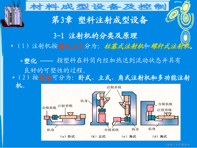
3.3 注射机有关工艺参数的校核
注射机类型
柱塞式 螺杆式
(1)对于单分型面模具的开模行程的校核
上海理工大学 陈泽中
S H1 H 2 (5 ~ 10) Smax Sk H m
上海理工大学 陈泽中
(2)对于双分型面模具的开模行程的校核
S H1 H 2 a (5 ~ 10) Smax Sk H m
上海理工大学 陈泽中
螺杆式较柱塞式多一旋转动作,产生分力(Ft),可使 材料在螺旋槽间产生混炼作用,增加了塑化能力。
上海理工大学 陈泽中
3.2 注射机技术参数 见表2-3,2-4
1、注射量 也称公称注射量,指空注射条件下注射
螺杆或注塞做一次最大注射行程时,注射装
置所能达到的最大注射量。
柱塞式注射机的最大注射量是以一次注射聚苯乙烯的最大克数为标准。 螺杆式注射机是以体积表示最大注射量,与塑料的品种无关。 选择时,实际注射量应为注射机公称注射量的 25%~70% 为宜。
F.安装螺孔尺寸
模具重量较轻用压板固定 模具重量较重的用螺钉固定
上海理工大学 陈泽中
G、开模行程的校核
注射机最大开模行程(S)与模具厚度(Hm )无关
对液压式合模装置,注塑机模座最大间距Sk 是个固定 值,注塑机最大模座行程Smax在△H范围内可调; 对液压机械式合模装置,注塑机最大模座行程Smax 是 个固定值,模座最大间距Sk在△H范围内可调。
injection molding

Injection MoldingIntroductionInjection molding is a widely used manufacturing process in the field of plastic production. It involves injecting molten material into a mold cavity, allowing it to cool and solidify, before ejecting the molded part. This process is known for its efficiency, accuracy, and versatility, making it suitable for producing a wide range of plastic products. In this document, we will explore the injection molding process, its advantages, limitations, and relevant considerations.The Injection Molding ProcessStep 1: ClampingThe first step in the injection molding process is clamping. The mold cavity is closed and clamped shut, ensuring that it remains tight and secure during the subsequent steps of the process. The clamping force is controlled depending on the size and complexity of the part being molded.Step 2: InjectionOnce the mold is clamped shut, the molten material, typically a thermoplastic polymer, is injected into the mold cavity through a nozzle. The material is heated and liquefied in a barrel before being pushed under high pressure into the mold. The molten material fills the cavity and takes the shape of the mold.Step 3: CoolingAfter the cavity is filled, the molten material is left to cool and solidify. Cooling time is determined by several factors, including material properties, part design, and thickness. It is crucial to control the cooling process to ensure uniform solidification and prevent defects such as warping or shrinkage.Step 4: EjectionOnce the molded part has cooled and solidified, the mold is opened, and the part is ejected. Ejection mechanisms such as pins or ejector plates are used to remove the part from the mold without causing damage.Step 5: Post-processingDepending on the requirements of the final product, additional post-processing steps may be required. This can include trimming excess material, adding surface finishes, or assembling multiple injected parts.Advantages of Injection MoldingInjection molding has numerous advantages over other manufacturing processes, including:EfficiencyInjection molding allows for high-volume production with minimal wastage. The process can produce a large number ofidentical parts within a short period, making it highly efficient for mass production.Cost-effectivenessOnce the initial mold is created, the cost per unit decreases significantly. This makes injection molding cost-effective for large-scale production runs, as the cost is spread over a large number of parts.Design flexibilityInjection molding offers design flexibility, allowing for the creation of intricate and complex parts. It enables the incorporation of features such as undercuts, threads, and varying wall thicknesses.Material optionsInjection molding supports a wide range of material options, including various thermoplastics and thermosetting plastics. This enables the production of parts with different physical properties, colors, and finishes.Limitations and ConsiderationsHigh initial costThe initial cost of tooling and mold creation can be high. However, this cost is typically offset by the cost savings achieved during large-scale productions runs.Design constraintsCertain design constraints apply to injection molding, such as draft angles and uniform wall thickness. These constraints are necessary to ensure proper mold filling, uniform cooling, and easy ejection of the part.Part size limitationsInjection molding is most suitable for producing small to medium-sized parts. Large parts may require special considerations and equipment.Parting line and gate designThe parting line, where the two halves of the mold meet, and the gate design are important considerations in injection molding. Proper placement of the parting line and gate helps prevent defects like sink marks or visible gate scars.Environmental impactInjection molding relies on the use of plastic materials, which can have a significant environmental impact. Proper disposal and recycling of plastic waste are crucial to mitigate these impacts.ConclusionInjection molding is a highly efficient and versatile manufacturing process for producing plastic parts. From the clamping of the mold to the ejection of the final part, each stepin the process is crucial to ensure high-quality parts. Understanding the advantages, limitations, and considerations of injection molding allows manufacturers to make informed decisions and optimize the production process.。
注塑成型与模具知识(一)
Metering 计量
Transition 过渡
L
Feed 进料
Screw and Cylinder Design 螺杆和料筒设计
L/D = 20:1 (16 ~ 24 :1) Compression Ratio压缩比 = hf / hm =2 ~ 2.5:1 (1.5 ~ 3 压缩比 :1)
g
RPM
150
推荐螺杆转速
转速
SCREW SPEED Suggestions
100
50
Screw Dia in mm
25 50 75 100 125
螺杆 150 直径
g
往复式螺杆头结构
检查环类型: 止回环
熔融树脂流过 开放检查环
检查环关闭, 防止在 注塑过程中料的回流
建议采用止逆阀
g
Standard Cylinder Nozzles 标准料筒喷嘴
合模 塑膠塑化
加料松退
2.射膠
當螺桿停止移動,在液壓缸或機械力作用下, 推動螺桿前進使熔体通過噴嘴注入模具.
加壓流動模具充填
射膠保壓
3.保壓
當模具充滿后流動速度減慢,此時塑膠被繼 續擠入模腔,熔體密度提高.
凝固及冷卻 開模 頂出
g
Injection Molding Process Important Process Variables 重要加工参数
注射量(實際 實際) 制件重量 = 30- 80% 机器 最大 注射量 實際 2-2.機器最大注塑量 實際 機器最大注塑量(實際 機器最大注塑量 實際): 機器注塑容量(實際 機器注塑容量(理論 實際)=機器注塑容量 理論)*P 機器注塑容量 實際 機器注塑容量 理論 M/PPS 機器注塑容量(理論 查機器參數. 理論): 機器注塑容量 理論 查機器參數 PM-----------使用原料比重 使用原料比重. 使用原料比重 PPS-----------聚苯乙烯(PS) 常溫下的比重 聚苯乙烯( 常溫下的比重(1.06g/cm3) 聚苯乙烯
MIM工艺
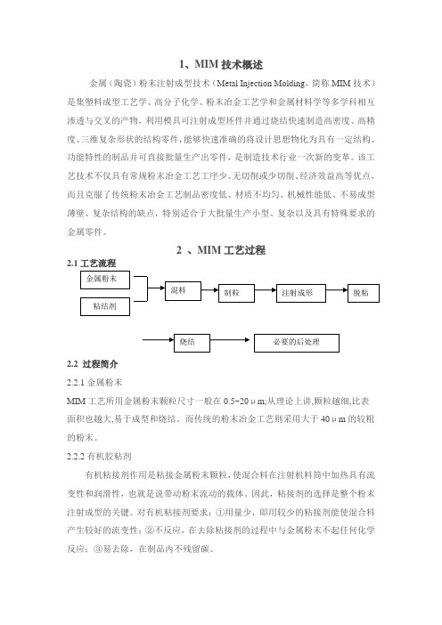
1、MIM 技术概述金属(陶瓷)粉末注射成型技术(Metal Injection Molding ,简称MIM 技术)是集塑料成型工艺学、高分子化学、粉末冶金工艺学和金属材料学等多学科相互渗透与交叉的产物,利用模具可注射成型坯件并通过烧结快速制造高密度、高精度、三维复杂形状的结构零件,能够快速准确的将设计思想物化为具有一定结构、功能特性的制品并可直接批量生产出零件,是制造技术行业一次新的变革。
该工艺技术不仅具有常规粉末冶金工艺工序少、无切削或少切削、经济效益高等优点,而且克服了传统粉末冶金工艺制品密度低、材质不均匀、机械性能低、不易成型薄壁、复杂结构的缺点,特别适合于大批量生产小型、复杂以及具有特殊要求的金属零件。
2 、MIM 工艺过程2.1工艺流程2.2 过程简介 2.2.1金属粉末MIM 工艺所用金属粉末颗粒尺寸一般在0.5~20μm;从理论上讲,颗粒越细,比表面积也越大,易于成型和烧结。
而传统的粉末冶金工艺则采用大于40μm 的较粗的粉末。
2.2.2有机胶粘剂有机粘接剂作用是粘接金属粉末颗粒,使混合料在注射机料筒中加热具有流变性和润滑性,也就是说带动粉末流动的载体。
因此,粘接剂的选择是整个粉末注射成型的关键。
对有机粘接剂要求:①用量少,即用较少的粘接剂能使混合料产生较好的流变性;②不反应,在去除粘接剂的过程中与金属粉末不起任何化学反应;③易去除,在制品内不残留碳。
2.2.3混练与制粒混练时把金属粉末与有机粘接剂均匀掺混在一起,将其流变性调整到适于注射成形状态的作用。
混合料的均匀程度直接影响其流动性,因而影响注射成型工艺参数乃至最终材料的密度及其它性能。
注射成形过程中产生的下角料、废品都可重新破碎、制粒,回收再用。
2.2.4注射成形本步工艺过程与塑料注射成型工艺过程在原理上是一致的,其设备条件也基本相同。
在注射成型过程中,混合料在注射机料筒内被加热成具有流变性的塑性物料,并在适当的注射压力下注入模具中,成型出毛坯。
模具毕业设计英译汉(Injection_molding)
Injection moldingInjection molding (British English: moulding) is a manufacturing process for producing parts from both thermoplastic and thermosetting plastic materials. Material is fed into a heated barrel, mixed, and forced into a mold cavity where it cools and hardens to the configuration of the mold cavity.After a product is designed, usually by an industrial designer or an engineer, molds are made by a moldmaker (or toolmaker) from metal, usually either steel or aluminum, and precision-machined to form the features of the desired part. Injection molding is widely used for manufacturing a variety of parts, from the smallest component to entire body panels of cars.ApplicationsInjection molding is used to create many things such as wire spools, packaging, bottle caps, automotive dashboards, pocket combs, and most other plastic products available today. Injection molding is the most common method of part manufacturing. It is ideal for producing high volumes of the same object.Some advantages of injection molding are high production rates, repeatable high tolerances, the ability to use a wide range of materials, low labor cost, minimal scrap losses, and little need to finish parts after molding. Some disadvantages of this process are expensive equipment investment, potentially high running costs, and the need to design moldable parts.EquipmentPaper clip mold opened in molding machine; the nozzle is visible at rightMain article: Injection molding machineInjection molding machines consist of a material hopper, an injection ram or screw-type plunger, and a heating unit. They are also known as presses, they hold the molds in which the components are shaped. Presses are rated by tonnage, which expresses the amount of clamping force that the machine can exert. This force keeps the mold closed during the injection process. Tonnage can vary from less than 5 tons to 6000 tons, with the higher figures used in comparatively few manufacturingoperations. The total clamp force needed is determined by the projected area of the part being molded. This projected area is multiplied by a clamp force of from 2 to 8 tons for each square inch of the projected areas. As a rule of thumb, 4 or 5 tons/in2 can be used for most products. If the plastic material is very stiff, it will require more injection pressure to fill the mold, thus more clamp tonnage to hold the mold closed. The required force can also be determined by the material used and the size of the part, larger parts require higher clamping force.MoldMold or die are the common terms used to describe the tooling used to produce plastic parts in molding.Since molds have been expensive to manufacture, they were usually only used in mass production where thousands of parts were being produced. Typical molds are constructed from hardened steel, pre-hardened steel, aluminum, and/or beryllium-copper alloy. The choice of material to build a mold from is primarily one of economics; in general, steel molds cost more to construct, but their longer lifespan will offset the higher initial cost over a higher number of parts made before wearing out. Pre-hardened steel molds are less wear-resistant and are used for lower volume requirements or larger components. The typical steel hardness is 38-45 on the Rockwell-C scale. Hardened steel molds are heat treated after machining. These are by far the superior in terms of wear resistance and lifespan. Typical hardness ranges between 50 and 60 Rockwell-C (HRC). Aluminum molds can cost substantially less, and, when designed and machined with modern computerized equipment, can be economical for molding tens or even hundreds of thousands of parts. Beryllium copper is used in areas of the mold that require fast heat removal or areas that see the most shear heat generated. The molds can be manufactured either by CNC machining or by using Electrical Discharge Machining processes.Mold DesignStandard two plates tooling –core and cavity are inserts in a mold base – "Family mold" of 5 different partsThe mold consists of two primary components, the injection mold (A plate) and the ejector mold (B plate). Plastic resin enters the mold through a sprue in the injection mold, the sprue bushing is to seal tightly against the nozzle of the injection barrel of the molding machine and to allow molten plastic to flow from the barrel into the mold, also known as cavity The sprue bushing directs the molten plastic to the cavity images through channels that are machined into the faces of the A and B plates. These channels allow plastic to run along them, so they are referred to as runners.The molten plastic flows through the runner and enters one or more specialized gates and into the cavity geometry to form the desired part.The amount of resin required to fill the sprue, runner and cavities of a mold is a shot. Trapped air in the mold can escape through air vents that are ground into the parting line of the mold. If the trapped air is not allowed to escape, it is compressed by the pressure of the incoming material and is squeezed into the corners of the cavity, where it prevents filling and causes other defects as well. The air can become so compressed that it ignites and burns the surrounding plastic material. To allow for removal of the molded part from the mold, the mold features must not overhang one another in the direction that the mold opens, unless parts of the mold are designed to move from between such overhangs when the mold opens (utilizing components called Lifters).Sides of the part that appear parallel with the direction of draw (The axis of the cored position (hole) or insert is parallel to the up and down movement of the mold as it opens and closes)are typically angled slightly with (draft) to ease release of the part from the mold. Insufficient draft can cause deformation or damage. The draft required for mold release is primarily dependent on the depth of the cavity: the deeper the cavity, the more draft necessary. Shrinkage must also be taken into account when determining the draft required.If the skin is too thin, then the molded part will tend to shrink onto the cores that form them while cooling, and cling to those cores or part may warp, twist, blister or crack when the cavity is pulled away. The mold is usually designed so that the moldedpart reliably remains on the ejector (B) side of the mold when it opens, and draws the runner and the sprue out of the (A) side along with the parts. The part then falls freely when ejected from the (B) side. Tunnel gates, also known as submarine or mold gate, is located below the parting line or mold surface. The opening is machined into the surface of the mold on the parting line. The molded part is cut (by the mold) from the runner system on ejection from the mold. Ejector pins, also known as knockout pin, is a circular pin placed in either half of the mold (usually the ejector half), which pushes the finished molded product, or runner system out of a mold.The standard method of cooling is passing a coolant (usually water) through a series of holes drilled through the mold plates and connected by hoses to form a continueous pathway. The coolant absorbs heat from the mold (which has absorbed heat from the hot plastic) and keeps the mold at a proper temperature to solidify the plastic at the most efficient rate.To ease maintenance and venting, cavities and cores are divided into pieces, called inserts, and sub-assemblies, also called inserts, blocks, or chase blocks. By substituting interchangeable inserts, one mold may make several variations of the same part.More complex parts are formed using more complex molds. These may have sections called slides, that move into a cavity perpendicular to the draw direction, to form overhanging part features. When the mold is opened, the slides are pulled away from the plastic part by using st ationary “angle pins” on the stationary mold half. These pins enter a slot in the slides and cause the slides to move backward when the moving half of the mold opens. The part is then ejected and the mold closes. The closing action of the mold causes the slides to move forward along the angle pins.Some molds allow previously molded parts to be reinserted to allow a new plastic layer to form around the first part. This is often referred to as overmolding. This system can allow for production of one-piece tires and wheels.2-shot or multi-shot molds are designed to "overmold" within a single molding cycle and must be processed onspecialized injection molding machines with two or more injection units. This process is actually an injection molding process performed twice. In the first step, the base color material is molded into a basic shape. Then the second material is injection-molded into the remaining open spaces. That space is then filled during the second injection step with a material of a different color.A mold can produce several copies of the same parts in a single "shot". The number of "impressions" in the mold of that part is often incorrectly referred to as cavitation. A tool with one impression will often be called a single impression(cavity) mold.A mold with 2 or more cavities of the same parts will likely be referred to as multiple impression (cavity) mold.Some extremely high production volume molds (like those for bottle caps) can have over 128 cavities.In some cases multiple cavity tooling will mold a series of different parts in the same tool. Some toolmakers call these molds family molds as all the parts are related.Effects on the material propertiesThe mechanical properties of a part are usually little affected. Some parts can have internal stresses in them. This is one of the reasons why it's good to have uniform wall thickness when molding. One of the physical property changes is shrinkage. A permanent chemical property change is the material thermoset, which can't be remelted to be injected again.Tool MaterialsTool steel or beryllium-copper are often used. Mild steel, aluminum, nickel or epoxy are suitable only for prototype or very short production runs.Modern hard aluminum (7075 and 2024 alloys) with proper mold design, can easily make molds capable of 100,000 or more part life.Geometrical PossibilitiesThe most commonly used plastic molding process, injection molding, is used to create a large variety of products with different shapes and sizes. Most importantly, they can create products with complex geometry that many other processes cannot. There are a few precautions when designing something that willbe made using this process to reduce the risk of weak spots. First, streamline your product or keep the thickness relatively uniform. Second, try and keep your product between 2 to20 inches.The size of a part will depend on a number of factors (material, wall thickness, shape,process etc.). The initial raw material required may be measured in the form of granules, pellets or powders. Here are some ranges of the sizes.MachiningMolds are built through two main methods: standard machining and EDM. Standard Machining, in its conventional form, has historically been the method of building injection molds. With technological development, CNC machining became the predominant means of making more complex molds with more accurate mold details in less time than traditional methods.The electrical discharge machining (EDM) or spark erosion process has become widely used in mold making. As well as allowing the formation of shapes that are difficult to machine, the process allows pre-hardened molds to be shaped so that no heat treatment is required. Changes to a hardened mold by conventional drilling and milling normally require annealing to soften the mold, followed by heat treatment to harden it again. EDM is a simple process in which a shaped electrode, usually made of copper or graphite, is very slowly lowered onto the mold surface (over a period of many hours), which is immersed in paraffin oil. A voltage applied between tool and mold causes spark erosion of the mold surface in the inverse shape of the electrode.CostThe cost of manufacturing molds depends on a very large set of factors ranging from number of cavities, size of the parts (and therefore the mold), complexity of the pieces, expected tool longevity, surface finishes and many others. The initial cost is great, however the piece part cost is low, so with greater quantities the overall price decreases.Injection processSmall injection molder showing hopper, nozzle and die areaWith Injection Molding, granular plastic is fed by gravity from a hopper into a heated barrel. As the granules are slowly moved forward by a screw-type plunger, the plastic is forced into a heated chamber, where it is melted. As the plunger advances, the melted plastic is forced through a nozzle that rests against the mold, allowing it to enter the mold cavity through a gate and runner system. The mold remains cold so the plastic solidifies almost as soon as the mold is filled.Injection Molding CycleThe sequence of events during the injection mold of a plastic part is called the injection molding cycle. The cycle begins when the mold closes, followed by the injection of the polymer into the mold cavity. Once the cavity is filled, a holding pressure is maintained to compensate for material shrinkage. In the next step, the screw turns, feeding the next shot to the front screw.This causes the screw to retract as the next shot is prepared. Once the part is sufficiently cool, the mold opens and the part is ejected.Molding trialWhen filling a new or unfamiliar mold for the first time, where shot size for that mold is unknown, a technician/tool setter usually starts with a small shot weight and fills gradually until the mold is 95 to 99% full. Once this is achieved a small amount of holding pressure will be applied and holding time increased until gate freeze off (solidification time) has occurred. Gate solidification time is an important as it determines cycle time, which itself is an important issue in the economics of the production process. Holding pressure is increased until the parts are free of sinks and part weight has been achieved. Once the parts are good enough and have passed any specific criteria, a setting sheet is produced for people to follow in the future. The method to setup an unknown mold the first time can be supported by installing cavity pressure sensors. Measuring the cavity pressure as a function of time can provide a good indication of the filling profile of the cavity. Once the equipment is set to successfully create the molded part, modern monitoring systems can save a reference curve of the cavity pressure. With that it is possible toreproduce the same part quality on another molding machine within a short setup time.Tolerances and SurfacesMolding tolerance is a specified allowance on the deviation in parameters such as dimensions, weights, shapes, or angles, etc. To maximize control in setting tolerances there is usually a minimum and maximum limit on thickness, based on the process used.Injection molding typically is capable of tolerances equivalent to an IT Grade of about 9–14. The possible tolerance of a thermoplastic or a thermoset is ±0.008 to ±0.002 inches. Surface finishes of two to four microinches or better are can be obtained. Rough or pebbled surfaces are also possible.Lubrication and CoolingObviously, the mold must be cooled in order for the production to take place. Because of the heat capacity, inexpensiveness, and availability of water, water is used as the primary cooling agent. To cool the mold, water can be channeled through the mold to account for quick cooling times. Usually a colder mold is more efficient because this allows for faster cycle times. However, this is not always true because crystalline materials require the opposite: a warmer mold and lengthier cycle time.InsertsMetal inserts can be also be injection molded into the workpiece. For large volume parts the inserts are placed in the mold using automated machinery. An advantage of using automated components is that the smaller size of parts allows a mobile inspection system that can be used to examine multiple parts in a decreased amount of time. In addition to mounting inspection systems on automated components, multiple axial robots are also capable of removing parts from the mold and place them in latter systems that can be used to ensure quality of multiple parameters. The ability of automated components to decrease the cycle time of the processes allows for a greater output of quality parts.Specific instances of this increased efficiency include the removal of parts from the mold immediately after the parts are created and use in conjunction with vision systems. Theremoval of parts is achieved by using robots to grip the part once it has become free from the mold after in ejector pins have been raised. The robot then moves these parts into either a holding location or directly onto an inspection system, depending on the type of product and the general layout of the rest of the manufacturer's production facility. Visions systems mounted on robots are also an advancement that has greatly changed the way that quality control is performed in insert molded parts. A mobile robot is able to more precisely determine the accuracy of the metal component and inspect more locations in the same amount of time as a human inspector.注塑成型注射制模(Injection moldin)是一种生产由热塑性塑料或热固性塑料所构成的部件的过程。
注塑机行业的英文资料

注塑机行业的英文资料注塑机行业的英文资料IntroductionInjection molding is a widely used manufacturing process in the plastic industry. It involves injecting molten plastic into a mold cavity and allowing it to cool and harden, resulting in the production of various plastic products. The injection molding machine, also known as an injection molding press, is a crucial piece of equipment in this process. In this document, we will provide valuable English resources and information about the injection molding machine industry.1. Types of Injection Molding MachinesThere are different types of injection molding machines available, each designed for specific applications. Some common types include:Hydraulic Injection Molding MachinesElectric Injection Molding MachinesHybrid Injection Molding MachinesEach type has its advantages and disadvantages, and the choice depends on factors such as production requirements, cost, and energy efficiency. Understanding the different types of injection molding machines can help manufacturers make informed decisions.2. Components of an Injection Molding MachineTo better understand how an injection molding machine works, it is essential to familiarize oneself with its components. The main components of an injection molding machine include:Injection unit: responsible for melting and injecting the plastic material into the mold.Clamping unit: holds the mold in place and applies pressure during the injection process.Mold temperature controller: maintains the temperature of the mold to ensure proper cooling and solidification of the plastic.Control system: controls and regulates the various functions of the injection molding machine.Having a good understanding of these components will enable operators to troubleshoot and maintain the machine efficiently.3. Key Considerations in Selecting an Injection Molding MachineWhen selecting an injection molding machine, several factors should be taken into account. These include:Production volume: the required number of plastic products to be produced.Material: different materials have unique characteristics and may require specific injection molding machines.Mold size: the size of the mold determines the size and tonnage capacity of the injection molding machine.Automation and customization options: some machines offer advanced automation and customization features, which can improve productivity and efficiency.By carefully evaluating these considerations, manufacturers can choose the most suitable injection molding machine for their specific needs.4. Challenges and Solutions in the Injection Molding Machine IndustryThe injection molding machine industry faces a range of challenges, but solutions have been developed to overcome these issues. Some common challenges include:Energy consumption: injection molding machines can consume a significant amount of energy. However, newer models are designed with energysaving features to reduce power consumption.Material waste: minimizing material waste is crucial for costeffectiveness and environmental sustainability. Advanced injection molding machines are equipped with precise control systems that can optimize material usage.Maintenance and troubleshooting: regular maintenance is essential for the efficient operation of injection molding machines. Manufacturers provide comprehensive manuals and guidelines to assist operators in troubleshooting common issues.5. Future Trends in the Injection Molding Machine IndustryThe injection molding machine industry continues to evolve, driven by technological advancements and changing market demands. Some future trends include:Introduction of electric and hybrid machines: electric injection molding machines are gaining popularity due to their energy efficiency and reduced environmental impact. Integration of Industry 4.0 technologies: smart manufacturing concepts are being integrated into injection molding machines, allowing for improved monitoring, control, and predictive maintenance.Development of new materials: as the demand for innovative materials grows, injection molding machines need to be capable of processing these materials effectively.ConclusionThe injection molding machine industry plays a vital role in the production of plastic products. Understanding the different types of machines, their components, and key considerations for selection is essential for manufacturers in this industry. Overcoming challenges and keeping up with future trends will ensure the continued success and growth of the injection molding machine industry.。
鞋子常见成型工艺英文怎么说
鞋子常见成型工艺英文怎么说在日常生活中,鞋子是我们不可或缺的一部分。
无论是运动鞋、皮鞋还是凉鞋,我们都非常关注鞋子的外形和舒适度。
而一个鞋子的外观完全取决于鞋子的成型。
那么,“鞋子成型”在英文中应该怎么表达呢?一、Injection molding(注塑成型)Injection molding是一种常见的鞋子成型工艺,即通过热塑性聚合物加热成液态,将液态聚合物注入模具中,冷却后即可得到所需鞋子的成型。
二、Compression molding(压缩成型)Compression molding也是一种鞋子常见的成型工艺。
它是将热塑性材料加热至软化状态后,放置于模具中进行压缩,待材料冷却硬化后,就可以得到所需鞋子的成型。
三、Blow molding(吹塑成型)Blow molding是指通过将塑料材料加热至熔融状态后,注入或吹气进入模具中,使塑料膨胀充满模具腔体,冷却后得到成型鞋子的一种成型工艺。
四、Extrusion molding(挤出成型)Extrusion molding是一种通过熔融的塑料材料在挤出机的作用下,通过模具的形状,挤出管状材料,并且在冷却后得到所需鞋子的成型。
五、Rotational molding(旋转成型)Rotational molding是一种通过将聚乙烯、聚丙烯等塑料粉末放入模具中,加入颜色和润滑剂,随后进行旋转和加热,使塑料粉末均匀附着在模具内表面上,冷却后取出得到所需成型鞋子的方法。
以上是常见的几种鞋子成型工艺,在不同的制鞋工艺中,可以根据产品要求选择相应的成型工艺。
鞋子的成型工艺不仅直接影响到鞋子的外观,还会对鞋子的舒适性、耐用度等方面有着重要的影响。
总结一下:Injection molding (注塑成型)、Compression molding(压缩成型)、Blow molding(吹塑成型)、Extrusion molding(挤出成型)、Rotational molding(旋转成型)是常见的几种鞋子成型工艺。
金属粉末注射成型

案例四:电子产品制造
总结词
微型化、高精度、轻量化
详细描述
金属粉末注射成型在电子产品制造中发挥着重要作用,尤其 在微型化、高精度和轻量化方面具有显著优势。例如,用于 制造手机、平板电脑等消费电子产品的金属结构件和连接件 等。
05
结论
金属粉末注射成型的重要性和应用前景
金属粉末注射成型是一种重要的金属加 工技术,具有高精度、高效率、低成本 等优点,广泛应用于汽车、航空航天、
未来发展方向
新材料研究与应用
随着新材料技术的不断发展,未来将有更 多具有优异性能的金属粉末应用于金属粉
末注射成型工艺。Βιβλιοθήκη 环保与可持续发展随着环保意识的提高,未来金属粉末注射 成型将更加注重环保和可持续发展,减少
生产过程中的废弃物和能耗。
智能化与自动化
通过引入先进的传感器、控制系统和人工 智能技术,实现金属粉末注射成型的智能 化和自动化,提高生产效率和产品质量。
探索金属粉末注射成型与其他 先进制造技术的结合,实现优 势互补,提高整体制造水平。
ABCD
加强新材料的研发和应用, 以满足市场需求和推动产 业升级。
加强国际合作和技术交流,引 进先进技术和理念,推动金属 粉末注射成型技术的全球发展 。
THANK YOU
型产品。
1970年代
随着粘结剂喷射和脱脂技术的 发展,金属粉末注射成型技术
逐渐成熟。
1980年代至今
金属粉末注射成型技术不断发 展和完善,应用领域不断扩大
。
应用领域
电子通讯
如连接器、端子、 线圈架等;
医疗器械
如手术器械、牙科 器械等;
汽车零件
如发动机零件、变 速器零件、刹车系 统零件等;
粉末注射成型

粉末注射成型
粉末注射成型(Powder Injection Moulding,简称PIM)是一种将金属或陶瓷粉末通过加工制造成零件的技术。
这
个过程类似于传统的塑料注射成型,但使用的是金属或陶
瓷粉末。
整个过程包括以下步骤:
1. 材料准备:选择合适的金属或陶瓷粉末,并按照特定的
配方制备成所需的粉末混合物。
2. 注射成型:将粉末混合物装入注射机中,并通过高压将
粉末推入模具中。
模具通常是具有所需形状的两个半球体。
3. 球芯去除:等到粉末充填到模具后,球芯会自动脱落并
迅速冷却固化。
4. 焙烧:固化的零件需要经过焙烧过程,以去除残留的有
机物,并增加材料的密度和强度。
5. 精加工:将焙烧后的零件进行必要的后续加工,例如打磨、抛光等。
6. 检测和质量控制:对成品进行检测,确保其符合规定的
尺寸和质量标准。
粉末注射成型技术具有许多优点,例如可以生产形状复杂的零件,材料利用率高,生产效率高等。
它被广泛应用于汽车、医疗器械、工具等领域的零部件制造。
Trouble Shooting Guide for Injection Molding Part1 注塑问题解决手册 (上)

01 Dull spots01 斑点(乌点)Alternative terms: Matt patches别名: 消光区域Description: Uniform, clearly defined velvety areas on surface描述: 制品表面上均匀的、清晰可见的绒面状区域Possible causes: 1 Disturbed melt flow in gating system or near gate1.1 Flow fronts with different velocities (with severalgating points)2 Tearing of already solidified outer skin at sharpbends and abrupt changes in wall thickness可能的原因 1 浇注系统中或靠近浇口处出现不规则熔料流1.1 不同速度的流动前锋 (多个浇口)2 急拐弯处和壁厚突变处已固化的外层料被撕裂Remedial actions: 1 Modify gate; start by injecting material slowly,解决的措施then switch to a faster speed1.1 Even out differences in flow front velocities byimproving the balance of the gating system (whereseveral feed points are involved)2 Round off or polish transition zones and abruptchanges in wall thickness in the runner and mould;balance flow front velocities1 修改浇口;采用先慢后快的充模方式1.1 通过均衡流道系统来减少不同流动前锋的速度差(多个浇口)。
注射成型设备

(2)立式注射机:注射机的注射装置轴线与合模装 置运动轴线呈一直线垂直排列。 占地面积小,模具拆装方便。但制品顶出后不易自动 脱落,不易实现全自动化操作,且机身高,加料、维修 不方便。目前这种形式主要用于小型注射机。
4. 根据物料在注射机料筒中的塑化方式不同,还可以 将注射机分为柱塞式注射机和螺杆式注射机两大类。
这将在下面注射机的注射系统部分作详细介绍。
第二节 注射机的基本参数与型号
一、注射机的规格型号
我国塑料注射成型机的型号编制方法由基本型号和 辅助型号两部分组成。基本型号和辅助型号之间用短线 隔开。
(3)角式注射机:注射机的注射装置与合模装置轴 线互成垂直排列(L型)。 其优缺点介于立式和卧式之间,使用也较普通,大、 中、小型注射机均有。
(4)多模注射机:多模注射机是一种多工位操作 的特殊注射机。合模装置有多个,按多种形式排列。
多模转盘式注射机
2.按机器加工能力分类 注射机加工能力可用机器的注射量和合模力两个参 数表示。
液压系统:由动力油泵、执行机构(油缸、油马达)、 各种控制阀组成。 电器控制系统:由各种电器、仪表、计算机控制部件组 成。
主要作用:为注射成型提供动力,实现动作控制,保 证注射成型正常进行。
四、注射机的分类
目前使用较多的分类方法有以下几种:
1 按设备外形特征分类 (1)卧式注射机:注射机的注射装置和合模装置的运动轴 线呈一直水平直线徘列。
1.注射装置:由塑化部件(料筒、螺杆、喷嘴等)、料斗、 计量装置、注射和移动油缸等组成。
主要作用:使聚合物均匀地塑化成熔融状态,并以足够的 压力和速度将定量的熔料注入模腔中。
全英文注塑资料注塑机结构

全英文注塑资料注塑机结构Injection Molding Machine Structure1. Injection Unit: The injection unit is responsible for melting and injecting the plastic material into the mold. It consists of a hopper, barrel, and screw. The plastic material is fed into the hopper, which then transfers it to the barrel. Inside the barrel, the plastic material is melted by the heating elements and the rotating screw. The screw also serves the purpose of pushing the molten plastic into the mold.2. Mold Clamping Unit: The mold clamping unit is responsible for securely holding the mold in place during the injection molding process. It consists of a clamping system, including a toggle mechanism or hydraulic system, that applies sufficient force to keep the mold closed. The clamping force is crucial to prevent any mold movement or leakage of molten plastic.3. Injection System: The injection system includes the injection unit and the mold clamping unit. It controls theentire injection molding process. The injection system has the capability to regulate and control the temperature, pressure, and speed of the molten plastic.7. Cooling System: The cooling system is essential torapidly cool down the molten plastic after injection. It prevents deformations and ensures the part's dimensionalaccuracy. The cooling system typically consists of cooling channels inside the mold and a cooling water circulation system outside the mold.。
injection plastic和plastic injection
injection plastic和plastic injection【注塑成型:一个广泛应用的塑料加工方法】引言:注塑成型(Injection Molding)是一种常见且广泛应用于塑料加工的方法。
该方法通过加热和压力等工艺,将塑料材料加工成各种形状的产品。
本文将以“Injection Plastic”和“Plastic Injection”为主题,详细介绍注塑成型的定义、流程、应用和未来的发展趋势。
一、注塑成型的定义注塑成型是一种将加热融化的塑料材料通过注射器注射进模具中,经过冷却和成型,制造出各种塑料制品的加工方法。
该方法被广泛应用于制造汽车零部件、家电配件、医疗用品、日用品等多个领域,具有高效、精确、重复性好等特点。
二、注塑成型的流程注塑成型涉及多个流程,主要包括:1. 塑料材料选择和预处理:选择合适的塑料原料,并进行预处理,如研磨、干燥等,以确保材料的质量和流动性能。
2. 模具设计和制造:根据产品的形状和尺寸要求,设计和制造注塑模具,模具通常由钢材制成,并经过精密切削加工。
3. 注塑机操作:将预处理后的塑料原料放入注塑机的料斗中,开启机器,使塑料经过加热、熔化、注射等工序,进入模具腔中。
4. 冷却和成型:在模具中,通过注塑机提供的压力和冷却系统,使熔化的塑料在模具中冷却和固化,最终成型为产品。
5. 脱模和后处理:冷却后,打开模具,取出成型的产品,进行后续的清洁、修整等工艺处理。
三、注塑成型的应用注塑成型广泛应用于多个领域,以下是其中的几个例子:1. 汽车工业:注塑成型在汽车工业中扮演着至关重要的角色,用于制造汽车的外壳、内饰、传感器、电器等零部件。
2. 家电行业:注塑成型用于制造家电产品的外壳、按钮、插座等配件,具有良好的外观和细节表现。
3. 医疗行业:医疗领域对产品的安全性和精确性要求极高,注塑成型在制造医疗设备、器械和耗材等方面发挥着重要作用。
4. 日用品:注塑成型制造了许多我们日常使用的日用品,如塑料勺子、刷子、笔等。
InjectionMolding1精品文档
Where would you gate this part?
Weld line, Sink mark
Gate
Mold Filling
Weld line
Solidified part
Sink mark
* Source: /proc/plastic/injection/injection_design_7.htm
1
v/h
Newtonian Viscosity
v h
Generalization: : shearrate
( )
Injection molding
Typical shear rate for Polymer processes (sec)-1
Extrusion
matching B.C.; matching I.C.
(,F O ) f(F O )g ()
Temperature in a slab Centerline, = 0.1, Fo = t/L2 = 1
Bi-1 =k/hL
Reynolds Number
Reynolds Number:
V2
Outline
Basic operation Cycle time and heat transfer Flow and solidification Part design Tooling New developments Environment
Readings
Tadmore and Gogos
For Die casting
Re31031100 31103 300
* Source: /proc/plastic/injection/injection_process.htm
- 1、下载文档前请自行甄别文档内容的完整性,平台不提供额外的编辑、内容补充、找答案等附加服务。
- 2、"仅部分预览"的文档,不可在线预览部分如存在完整性等问题,可反馈申请退款(可完整预览的文档不适用该条件!)。
- 3、如文档侵犯您的权益,请联系客服反馈,我们会尽快为您处理(人工客服工作时间:9:00-18:30)。
Boothroyd Dewhurst
Design for Injection Molding pp 319 - 359
Kalpakjian see Ch 18 Injection molding case study;Washing machine augers; see on web page
30 ton, 1.5 oz (45 cm3) Engel
Injection Molding Machine for wheel fabrication
Process & machine schematics
*
*
Schematic of thermoplastic Injection molding machine
Basic rules in designing ribs to minimize sink marks
Injection Molding
* *
* Source: /proc/plastic/injection/injection_design_2.htm
Gate Location and Warping
Sprue
2.0
60
Shrinkage
Direction of flow – 0.020 in/in
1.96
60.32
Perpendicular to flow – 0.012
2.0
Before shrinkage
1.976
After shrinkage
Effects of mold temperature and pressure on shrinkage
Shrinkage Shrinkage
0.030 0.025 0.020 0.015 0.010 0.005 0.000
LDPE
PP Acetal
Nylon 6/6
PMMA
100
120 140 160 180 200 220 240
Mold Temperature (F)
0.030 0.025 0.020 0.015 0.010 0.005 0.000
LDPE
PP with flow
PP across flow
Acetal
Nylon 6/6
PMMA
6000
10000
14000
18000
8000
12000
16000
Pressure on injection plunger (psi)
Rate of Temperature rise
cp
dT dt
v 2
h
or
dT
v
2
dt cp h
Rate of Conduction out
dT dt
k
cp
d 2T dx2
~
k
cp
T h2
Viscous heating v2
Center gate: radial flow – severe distortion
Air entrapment Gate
Edge gate: warp free, air entrapment
Diagonal gate: radial flow – twisting
End gates: linear flow – minimum warping
matching B.C.; matching I.C.
(, FO)
f (FO)g()
Temperature in a slab Centerline, = 0.1, Fo = t/L2 = 1
Bi-1 =k/hL
Reynolds Number
Reynolds Number:
V2
F=P X A = 420 tons
3.8 lbs = 2245 cm3 =75 oz
Actual ; 2 cavity 800 ton
Clamp force and machine cost
Heat transfer Note; Tool > polymer
1-dimensional heat conduction equation :
Injection mold die cast mold
Fountain Flow
*
**
* Source: /trp/inj/flw_froz.html ; ** Z. Tadmore and C. Gogos, “Principles of Polymer Processing”
2nd kind 3rd kind
k T (x x') constant x T
k x (x x') h (T T )
The boundary condition of 1st kind applies to injection molding since the tool is often maintained at a constant temperature
Where is injection molding?
Ltotal = Lmold + Lshrinkage
Re L
V L2
inertia VL viscous
For typical injection molding
1g cm3 103 N m4 s2 ; LZ 103 m thickness
V Part length 101 ; Fill time 1s
103 N s m2
0.1cm 10cm
2.5
For Die casting of aluminum
Flow rate Heat xfer rate
~
1 4
10cm / s 0.1cm 0.3cm2 / s
0.1cm 10cm
102
* Very small, therefore it requires thick runners
Conduction kT
Brinkman number
For injection molding, order of magnitude ~ 0.1 to 10
Non-Isothermal Flow
Flow rate: 1/t ~V/Lx
v
Heat transfer rate: 1/t ~a/(Lz/2)2
Shrinkage distributions
sample V=3.5cm/s V=8cm/s
Transverse direction
* Source: G. Menges and W. Wubken, “Influence of processing conditions on Molecular Orientation in Injection Molds”
Ti TW
x 1;
L
FO
t
L2
Dimensionless equation:
Initial condition Boundary condition
2 FO 2
FO 0 1 0 0 2 0
Separation of variables ;
qx
qx + qx
Fourier’s law
t
(
cp
T )xy
qx x
xy
T qx k x
cp
T t
k
2T x 2
or
T t
2T x 2
Boundary Conditions: 1st kind
T (x x') constant
Outline
Basic operation Cycle time and heat transfer Flow and solidification Part design Tooling New developments Environment
Readings
Tadmore and Gogos
Injection Molding
2.810 Fall 2002 Professor Tim Gutowski
Short history of plastics
1862 first synthetic plastic 1866 Celluloid 1891 Rayon 1907 Bakelite 1913 Cellophane 1926 PVC 1933 Polyethylene 1938 Teflon 1939 Nylon stockings 1957 velcro 1967 “The Graduate”
For Die casting
Re
3103 10 1 10 3 10 3Fra bibliotek 300
* Source: /proc/plastic/injection/injection_process.htm
Re 104
Viscous Shearing of Fluids
* Source: /proc/plastic/injection/injection_process.htm
Process Operation
Temperature: barrel zones, tool, die zone Pressures: injection max, hold Times: injection, hold, tool opening Shot size: screw travel