API650计算书
API-650-1
钢制焊接石油储罐API STANDARD 6501998年11月第十版美国石油学会翻译:王洪超校对:朱翌总目录第1章范围1.1 概述1.2 限制条件1.3 符合性1.4 参考文献第2章材料2.1 概述2.2 钢板2.3 薄板2.4 结构型钢2.5 钢管和锻件2.6 法兰2.7 螺栓2.8 焊条第3章设计3.1 焊接接头3.2 设计考虑3.3 特殊考虑3.4 罐底板3.5 环形罐底板3.6 罐壁设计3.7 罐壁开孔3.8 罐壁连接件和罐的附件3.9 顶部和中部抗风圈3.10 罐顶3.11 储罐上的风载荷(倾覆稳定性)第4章制造4.1 概述4.2 车间检验第5章安装5.1 概述5.2 焊接细节5.3 检查、试验和返修5.4 焊缝返修5.5 尺寸公差第6章检查焊接接头的方法6.1 射线照相检测6.2 磁粉检测6.3 超声波检测6.4 液体渗透检测6.5 目视检测6.6 真空试验第7章焊接工艺和焊工评定7.1 定义7.2 焊接工艺评定7.3 焊工评定7.4 焊接接头标识第8章标志8.1 铭牌8.2 职责范围8.3 证书附录A 小型储罐可选择的设计准则附录B 地面上储油罐基础设计和建造的建议附录C 外浮顶附录D 技术咨询附录E 储罐的抗震设计附录F 低内压储罐设计附录G 结构支撑型铝拱顶附录H 内浮顶附录I 罐底泄漏检测和地基保护附录J 车间组装的储罐附录K 运用“变设计点法”确定罐壁钢板厚度的示例附录L API 650标准储罐数据表附录M 提高温度下储罐的操作要求附录N 与本标准所列规范不一致的新材料的要求附录O 罐底连接的建议附录P 罐壁开孔处允许的外载荷附录S 奥氏体不锈钢储罐附录T 无损检测要求概要附录TI 技术询问回复图2-1 不做冲击试验的罐壁材料的最低允许设计金属温度2-2 最低日平均温度等温线2-3 罐壁接管和人孔材料确定冲击试验的控制厚度3-1 典型的罐壁纵向接头3-2 典型的罐壁环向接头3-3A 典型的罐顶和罐底接头3-3B 罐壁下预制搭接焊罐底板的方法3-3C 公称厚度大于13mm(1/2in)的环形罐底板双面填脚坡口焊缝详图3-4A 罐壁人孔3-4B 罐壁人孔和接管详图3-5 罐壁接管3-6 焊缝最小间距和有关射线照相检测的范围3-7 罐壁接管法兰3-8 确定齐平型清扫孔最小补强面积的系数3-9 齐平型清扫孔3-10 齐平型清扫孔的支撑3-11 齐平型罐壁连接件3-12 罐壁连接件的转动3-13 罐顶人孔3-14 法兰盖连接的罐顶矩形开孔3-15 具有铰链盖的罐顶矩形开孔3-16 罐顶法兰接管3-17 罐顶螺纹接管3-18 集液槽3-19 脚手架缆绳支撑3-20 罐壁上典型的加强圈截面3-21 通过加强圈的盘梯开孔3-22 按照3.7.3节罐壁上开孔的最低焊缝要求6-1 罐壁抽样射线照相要求8-1 制造厂铭牌8-2 制造厂证书A-1 齐平型螺栓紧固覆盖门A-2 齐平型螺栓紧固覆盖门支座A-3 突起型螺栓紧固覆盖门B-1 混凝土环墙基础示例B-2 碎石环墙基础示例E-1 震区分布图E-2 有效质量E-3 地震力的重心E-4 系数kE-5 压缩力bF-1 附录F的决定流程图F-2 允许的抗压环详图G-1 增加到现有储罐上的结构支撑铝拱顶数据G-2 典型的罐顶接管I-1 储罐周围具有罐底泄漏检测的混凝土环墙I-2 储罐周围具有罐底泄漏检测的碎石环墙I-3 储罐周围具有罐底泄漏检测的土基础I-4 储罐周围具有泄漏检测的双层钢罐底I-5 储罐周围具有泄漏检测的双层钢罐底I-6 储罐周围具有泄漏检测的钢筋混凝土板I-7 用以泄漏检测的具有径向沟的钢筋混凝土板I-8 典型集液槽I-9 向下倾斜罐底的中心集液槽I-10 典型的泄漏检测井I-11 格排构件支撑的储罐O-1 有混凝土环墙基础的罐底连接示例O-2 有混凝土环墙基础的罐底连接和改进的罐底/罐壁支撑的示例O-3 土基础的罐底连接示例P-1 管线载荷与变形的术语P-2A 径向载荷刚度系数:罐壁上的补强P-2B 纵向力矩刚度系数:罐壁上的补强P-2C 环向力矩刚度系数:罐壁上的补强P-2D 径向载荷刚度系数:罐壁上的补强P-2E 纵向力矩刚度系数:罐壁上的补强P-2F 环向力矩刚度系数:罐壁上的补强P-2G 径向载荷刚度系数:仅接管颈部上的补强P-2H 纵向力矩刚度系数:仅接管颈部上的补强P-2I 环向力矩刚度系数:仅接管颈部上的补强P-2J 径向载荷刚度系数:仅接管颈部上的补强P-2K 纵向力矩刚度系数:仅接管颈部上的补强P-2L 环向力矩刚度系数:仅接管颈部上的补强P-3A 建立b1、b2、c1、c2为边线的诺模图P-3B 建立b1、c3为边线的诺模图P-4A 确定系数Y F和Y LP-4B 确定系数Y CP-5A 由诺模图确定许用载荷:F R和M LP-5B 由诺模图确定许用载荷:F R和M CP-6 仅管颈补强的低型接管P-7 例题的许用载荷诺模图表1-1 API 650标准的附录状态2-1 最大允许合金含量2-2 按国家标准制造的板材的可接收等级2-3a 材料分组国际单位制2-3b 材料分组美国通用单位制2-4 钢板冲击试验的最低要求3-1 环形罐底板的厚度3-2 允许使用的板材和许用应力3-3 罐壁人孔盖板和螺栓紧固法兰的厚度3-4 罐壁人孔颈厚度尺寸3-5 罐壁人孔螺栓圆直径D b和盖板直径D c的尺寸3-6 罐壁接管尺寸3-7 罐壁接管尺寸:管子、钢板和焊接明细表3-8 罐壁接管法兰的有关尺寸3-9 齐平型清扫孔的有关尺寸3-10 齐平型清扫孔的盖板、螺栓法兰和底部补强板的最小厚度3-11 齐平型清扫孔罐壁补强板的厚度和高度3-12 齐平型罐壁连接件的尺寸3-13 罐顶人孔的尺寸3-14 罐顶法兰接管尺寸3-15 罐顶螺纹接管尺寸3-16 排液槽尺寸3-17 平台和通道的要求3-18 盘梯要求3-19 盘梯相邻踏步之间的高度、水平距离和角度的关系3-20 罐壁上加强圈的截面模数A-1a 1800mm宽罐壁筒节储罐的典型尺寸和相应的公称容积A-1b 72in宽罐壁筒节储罐的典型尺寸和相应的公称容积A-2a 1800mm宽罐壁筒节储罐典型尺寸的壁板厚度A-2b 72in宽对焊罐壁筒节储罐典型尺寸壁板厚度A-3a 2400mm宽罐壁筒节储罐的典型尺寸和相应的公称容积A-3b 96in宽罐壁筒节储罐的典型尺寸和相应的公称容积A-4a 2400mm宽罐壁筒节储罐的典型尺寸的壁板厚度A-4b 96in宽罐壁筒节储罐的典型尺寸的壁板厚度A-5 齐平型螺栓紧固覆盖门A-6 突起型螺栓紧固覆盖门E-1 美国以外震区分布E-2 场地区系数E-3 地区系数F-1 设计压力小于等于18kpa(21/2lbf/in2)的储罐锚固件的设计应力G-1 螺栓和紧固件J-1 车间组装锥顶罐的最大顶部深度K-1 采用宽2400mm(96in),在试验条件下许用应力为159MPa (23,000lbf/in2)的钢板,按“变设计点法”计算的罐壁钢板厚度K-2 采用宽2400mm(96in),在试验条件下许用应力为208MPa (30,000lbf/in2)的钢板,按“变设计点法”计算的罐壁钢板厚度K-3 采用宽2400mm(96in),在试验条件下许用应力为236MPa (34,3000lbf/in2)的钢板,按“变设计点法”计算的罐壁钢板厚度L-1 买方可能要求的决定或说明的索引M-1 屈服强度的降低系数M-2 最高操作温度下的弹性模量O-1 罐底连接件的尺寸P-1 设计温度下的弹性模量和热膨胀系数S-1a 不锈钢部件用的ASTM材料(国际单位制)S-1b 不锈钢部件用的ASTM材料(美国通用单位制)S-2 罐壁许用应力S-3 环板法兰的许用应力S-4 接头系数S-5 为单位的屈服强度值MPa (psi )S-6 最高操作温度下的弹性模量钢制焊接石油储罐1范围1.1概述1.1.1 本标准包括立式的、圆筒形的、地面上的、密闭的和敞开顶的、内压接近大气压的(内压不超过储罐顶板的重量)各种尺寸和容量的钢制焊接储罐的材料、设计、制造、安装和试验要求,当符合1.1.10的附加要求时,也适用于较高压力的储罐。
API-650储罐计算书
API 650储罐计算书内径:12.5米高度:9米设计内、外压: 2KPa/500PaTable of ContentsUser Input Data (3)Error Checker .LOG File (8)Wind, Material, Thickness & Weights (9)Roof Evaluation/Design & Appendix F (12)Seismic Analysis Results (13)Anchor Bolt Details (15)API-650 App I Grillage Review (16)API-650 App V External Pressure (17)Anchor Chair Calculations (18)Fluid Height Calculations (20)Wind Calculations (22)Thickness Calculations (24)Appendix F Calculations (27)Bolt Load Calculations (29)Seismic Analysis (31)Appendix V External Pressure (39)API-650/653 GENERAL TANK DATA :API-650 11th Edition, Addendum 3, Aug. 2011API Design Code ( 650 or 653 ) (650)Design Method (V, O, or A) ............................ O(V=variable, O=one foot, A=Appendix A)Run Objective (D=design, A=analyze) ................... ADesign Temperature ...............................(C ) 93.000Design Pressure at Top ....................(KPa ) 2.0000Shell Material ........................................ A-36Ratio of Normal Operating Pressure/Design Pressure [Fp] 0.40000Shell Design Stress [Sd] ..................(KPa ) 0.15995E+06 Shell Hydro Test Stress [St] ..............(KPa ) 0.17168E+06Tank Nominal Diameter [D] ........................(m. ) 12.500Tank Shell Height [HTK] ..........................(m. ) 9.0000Design Liquid Level [H] ..........................(m. ) 9.0000Liquid Specific Gravity [G] ........................... 0.85000Weight of Attachments/Structures..................(N. ) 30000.Distance down to Top Wind Girder .................(m. ) 0.00000 Joint Efficiency (App A or 653) [E] ................... 1.0000Wind Velocity .............................(M./sec. ) 37.500Insulation Thickness .............................(mm.) 40.000Insulation Density ........................(kg./cu.cm.) 0.22000E-03Include Annular Base Plate Details .................... YesInclude Wind Moment in Appendix F_4_2 Calculations .... YesNumber of Shell Courses (4)Shell Course # 1 Height ..........................(m. ) 2.2500Shell Course # 1 Thickness .......................(mm.) 10.000Shell Course # 1 Corrosion Allowance [CA] ........(mm.) 1.6000Shell Course # 2 Height ..........................(m. ) 2.2500Shell Course # 2 Thickness .......................(mm.) 10.000Shell Course # 2 Corrosion Allowance [CA] ........(mm.) 1.6000Shell Course # 3 Height ..........................(m. ) 2.2500Shell Course # 3 Thickness .......................(mm.) 10.000Shell Course # 3 Corrosion Allowance [CA] ........(mm.) 1.6000Shell Course # 4 Height ..........................(m. ) 2.2500Shell Course # 4 Thickness .......................(mm.) 10.000Shell Course # 4 Corrosion Allowance [CA] ........(mm.) 1.6000TANK SHELL COURSE MATERIALS :Shell Course # 1 Material Name ........................ A-36Shell Course # 1 Design Stress [Sd] .......(KPa ) 0.15995E+06 Shell Course # 1 Hydro Test Stress [St] ...(KPa ) 0.17168E+06 Shell Course # 1 Minimum Yield Stress .....(KPa ) 0.24821E+06 Shell Course # 1 Minimum Tensile Stress ...(KPa ) 0.39989E+06 Shell Course # 1 Maximum Thickness ..............(mm. ) 19.050Shell Course # 1 Material Grade .......................Shell Course # 1 Material Group (1)Shell Course # 2 Material Name ........................ A-36Shell Course # 2 Design Stress [Sd] .......(KPa ) 0.15995E+06 Shell Course # 2 Hydro Test Stress [St] ...(KPa ) 0.17168E+06 Shell Course # 2 Minimum Yield Stress .....(KPa ) 0.24821E+06 Shell Course # 2 Minimum Tensile Stress ...(KPa ) 0.39989E+06 Shell Course # 2 Maximum Thickness ..............(mm. ) 19.050Shell Course # 2 Material Grade .......................Shell Course # 2 Material Group (1)Shell Course # 3 Material Name ........................ A-36Shell Course # 3 Design Stress [Sd] .......(KPa ) 0.15995E+06 Shell Course # 3 Hydro Test Stress [St] ...(KPa ) 0.17168E+06 Shell Course # 3 Minimum Yield Stress .....(KPa ) 0.24821E+06 Shell Course # 3 Minimum Tensile Stress ...(KPa ) 0.39989E+06 Shell Course # 3 Maximum Thickness ..............(mm. ) 19.050Shell Course # 3 Material Grade .......................Shell Course # 3 Material Group (1)Shell Course # 4 Material Name ........................ A-36Shell Course # 4 Design Stress [Sd] .......(KPa ) 0.15995E+06 Shell Course # 4 Hydro Test Stress [St] ...(KPa ) 0.17168E+06 Shell Course # 4 Minimum Yield Stress .....(KPa ) 0.24821E+06 Shell Course # 4 Minimum Tensile Stress ...(KPa ) 0.39989E+06 Shell Course # 4 Maximum Thickness ..............(mm. ) 19.050Shell Course # 4 Material Grade .......................Shell Course # 4 Material Group (1)ANCHOR BOLT DETAILS :Anchor Bolt Diameter (optional) ..................(mm.) 44.450Threads per Unit Length ........................(1/mm.) 0.19685Bolt Allowable Stress .....................(KPa ) 0.15000E+06 Number of Anchor Bolts (optional) ..................... 20.000Bolt Yield Stress .........................(KPa ) 0.25000E+06 Bolt Offset from Mean Tank Diameter ..............(m. ) 0.10000Anchor Bolt Corrosion Allowance (optional) .......(mm.) 3.0000Wind Data :Kz parameter .......................................... 1.0400Kzt parameter ......................................... 1.0000Kd parameter .......................................... 0.95000Importance Factor (I) ................................. 1.0000Gust Factor (G) ....................................... 0.85000API-650 ROOF DETAILS SPECIFICATION :Roof Type (1-4) (4)(1=Supt Cone 2=Rafter Supt Cone 3=Cone 4=Dome 5=Umbrella)Angle Between Roof and Horizontal ................(deg) 24.610Net Area at Roof/Shell Junction [A] ...........(sq.mm.) 2000.5Thickness of Roof Plate ..........................(mm.) 10.000Roof Plate Corrosion Allowance ...................(mm.) 1.6000Weight of Snow on Roof ...........................(N. ) 0.00000 Roof Live Load ............................(N/M2 ) 1200.0---/ For General Roof, No Design /---Weight of Roof Plates ............................(N. ) 0.00000 Weight of Roof Framing ...........................(N. ) 0.00000 Pct of Weights Supported by Shell ..................... 0.00000---/ For Supported Cone Roof Design /---Preferred Rafter Type (W, WT, S, C) ...................Preferred Girder Type (W, WT, S, C) ...................Preferred Column Type (W, WT, S, C, DC, DI, P ) .......Roof Plate Material ................................... A-36Roof Plate Allowable Design Stress ........(KPa ) 0.15995E+06 Structural Member Material ............................ A-36Structural Member Allowable Design Stress..(KPa ) 0.15995E+06 Maximum Allowed Rafter Length ....................(m. ) -0.30788Maximum Allowed Girder Length ....................(m. ) -0.30788Center Column Cap Plate Diameter .................(m. ) 0.00000API-650 SEISMIC DATA (App E.) :Minimum Yield Strength of Bottom Plate .....(KPa 0.25000E+06 Minimum Yield Strength of Weld Material ....(KPa 0.25000E+06 Nominal Thickness of Bottom Plate (tb) ..........(mm. ) 8.0000Seismic Use Group (SUG)................................ 1.0000Friction Factor ....................................... 0.40000Importance Factor ..................................... 1.0000Initial Anchorage Type ................................ MEarthquake Type ....................................... SSite Class ............................................ 3.0000Spectral Acceleration Adjustment Coefficient (K) ...... 1.5000Scaling Factor (Q) .................................... 0.66700Transtiional Period (TL) .............................. 4.0000Mapped maximum earthquake for short periods (Ss) ...... 0.00000 Mapped maximum earthquake for 1 sec periods (S1) ...... 0.00000 Mapped maximum earthquake for 0 sec period (S0) ...... 0.00000 Non-ASCE peak ground acceleration (Sp) ................ 2.3000ASCE short period design acceleration parameter (SDS).. 0.00000 --- Site Specific Data ---Spectral acceleation parameter at 0 period (Sa0*) ..... 0.00000 Spectral acceleation parameter at any period (Sa*) .... 0.00000API-650 GRILLAGE REVIEW (App I.)Modulus of Elasticity of Bottom Plate .....(KPa ) 0.20200E+09 Corrosion Allowance added to Bottom Plate ......(mm. ) 1.5000Minimum Yield Strength of Bottom Plate ....(KPa ) 0.25000E+06 (Equal to Value from Seismic Data)SPECIFY ONE OF THE FOLLOWINGNominal Thickness of Bottom Plate ...............(mm. ) 8.0000(Equal to Value from Seismic Data )Maximum Allowed Spacing .........................(mm. ) 416.83API-650 External Pressure (App V.) :Specified External Pressure (Pe) ..........(N/M2 ) 500.00Elastic Modulus of Roof Plate Material ....(KPa ) 0.19900E+09 Bottom stiffener allow. compressive stress (KPa ) 0.15000E+06 Top stiffener allow. compressive stress ...(KPa ) 0.15000E+06 Nominal Thickness of Bottom Plate (tb) ..........(mm. ) 8.0000Smallest allowable tensile stress of roof,shell and stiffeners ....................(KPa ) 0.15000E+06 Roof Dish Radius ................................(m. ) 15.000Computation Control DirectivesROOF_PROJECTION_IN_WIND_MOMENT= YESSHELL_THICK_CONVERG_TOLERANCE= 0.12699999 mm.GENERATE_MESSAGE_FILE= NOCOSINE_CURVE_TOLERANCE= 0.30000001COSINE_CURVE_ITERATION_LIMIT= 100.00000WIND_GIRDER_SHELL_THICKNESS= MAXSHELL_SETTLEMENT_METHOD= FOURIER_SERIESCORRODED_NOZZLES= NO653_CORRODED_HYDROTEST_CASE= NOTHICKNESS_ROUNDUP_TO_NEAREST= 0.00000000 mm.PLATE_MATERIAL_DENSITY= 0.78500481E-02 kg./cu.cm. MODIFY_FLUID_HEIGHT_BY_PRESSURE= NOROUND_ANCHOR_BOLTS_BY= 4.0000000WIND_MOMENT_IN_APP_F= Sect_5.9.7.1FULL_SHELL_WEIGHT_IN_APP_F= YESUSE_P_FROM_F.4.1_ONLY_IN_F.6= YESUSE_NON_CORRODED_ROOF_WEIGHT_AS_DLR= NOYIELD_FOR_SEISMIC_IS_DERATED_FOR_TEMP= NOTANK(c) Intergraph CADWorx & Analysis Solutions, Inc. 2013C:\Users\yang\Desktop\法罗杰项目\大罐计算书\T-2303-zyh\新建文件夹\ Error Check Summary ReportFatal Errors 0Warning Messages 0Notes 0Error Checking CompletedWIND INFORMATIONAPI-650 11th Edition, Addendum 3, Aug. 2011Wind Velocity ............................(M./sec. ) 37.500Velocity Factor ...................................... 0.48866Wind Pressure ............................(KPa ) 0.96372Area Exposed to Wind .....................(m. **2) 131.22Sect 5.9.7.1 Wind Moment on Tank .........(N.m. ) 0.66347E+06 Wind Shear Force Acting on Tank ..........(N. ) 0.12646E+06MATERIAL PROPERTY INFORMATIONWind Girder Height Reduction Factor .................. 1.0000The following material properties have been modified inaccordance with API-650 (and API-653 where applicable).Course Material Design Test App MNumber Name Stress (Sd) Stress (St) Reduction(KPa ) (KPa )1 A-36 0.15995E+06 0.17168E+06 1.00002 A-36 0.15995E+06 0.17168E+06 1.00003 A-36 0.15995E+06 0.17168E+06 1.00004 A-36 0.15995E+06 0.17168E+06 1.0000SHELL COURSE THICKNESS DATA - One Foot MethodThickness Values for Three Cases MIN TEMPCOURSE DESIGN TEST USER (deg C )(mm. ) (mm. ) (mm. ) Status1 6.0000 6.0000 10.000 -8.8 PASS2 5.0000 5.0000 10.000 -8.8 PASS3 5.0000 5.0000 10.000 -8.8 PASS4 5.0000 5.0000 10.000 -8.8 PASSNote, "ANALYSIS" mode has been activated. From thispoint on, the user specified thicknesses will be usedfor all calculations. The above values for DESIGN andTEST thicknesses are for reference purposes only.SHELL COURSE ALLOWED FLUID HEIGHTSFluid Heights for Three CasesCOURSE DESIGN TEST REQUIRED(m. ) (m. ) (m. )1 26.107 28.328 9.00002 26.107 28.328 6.75003 26.107 28.328 4.50004 26.107 28.328 2.2500Maximum allowed fluid height of entire tank for:Design Thickness Case .................(m. ) 26.107Test Thickness Case .................(m. ) 28.328Required fluid height .................(m. ) 9.0000BASE PLATE DETAILS - SHELL WEIGHT & CENTER OF GRAVITYAnnular Base Plate Thickness .............(mm. ) 7.6000(from API-650 Table 5-1 plus corrosion)Annular Base Plate Width per 5.5.2 .......(mm. ) 670.40( 2 + ThkCrs1 + max[ 24, (390tb / sqrt(HG))] )Weight of Shell + Nozzles ................(N. ) 0.30269E+06 Total Weight of all Nozzles ..............(N. ) 0.00000 Center of Gravity (Shell+Nozzles) ........(m. ) 4.5000WIND OVERTURNING STABILITY CHECKCorroded Shell Weight + %Roof - Uplift ...(N. ) 0.19098E+06 wa .......................................(N./cm. ) 159.04Mw - moment due to wind (hor+ver) press ..(N.m. ) 0.75290E+06 Mpi - moment due to internal pressure ....(N.m. ) 0.15340E+07 Mf - moment due to tank liquid ...........(N.m. ) 0.39035E+07 Mdl - moment due to shell & roof .........(N.m. ) 0.18072E+07WIND GIRDER INFORMATIONFor "open top" tanks ...Required Section Modulus, Top Girder ...(mm. **3) 39767.Table 5-20 Detail, B value .............(mm. ) c 0.00Table 5-20 Shape name (if applicable)............... 4x3x.25Maximum Height of Unstiffened Shell ......(m. ) 138.59WIND GIRDER - TRANSFORMED SECTION METHODNumber of Intermediate Girders Reqd 0WEIGHT SUMMARY--------------Shell (Corroded) .............................(N. ): 228534. Shell (Non-Corroded) .........................(N. ): 272065. Annular Base Plate ...........................(N. ): 14701. Bottom Plate .................................(N. ): 76807. Nozzles ......................................(N. ): 0. Roof Plates ..................................(N. ): 106247. Roof Framing/Structure .......................(N. ): 0.Shell Attachments ............................(N. ): 30000. Insulation ...................................(N. ): 30621. Operating Fluid ..............................(N. ): 9187119. Water Weight .................................(N. ): 10808375.Operating Weight (Non-Corroded) ..............(N. ): 9717560. Test Weight (Non-Corroded) ...................(N. ): 11338816. Empty Weight (Non-Corroded) ..................(N. ): 530441.TANK(c) Intergraph CADWorx & Analysis Solutions, Inc. 2013TANK - Roof Design/Analysis DataAPI-650 11th Edition, Addendum 3, Aug. 2011SELF-SUPPORTING DOME ROOFRoof thickness per 5.10.6, 0.8D ......(mm. ): 5.7814Roof thickness per 5.10.6, 1.2D ......(mm. ): 7.8720Total weight of Roof Plates ...........(N. ): 0.10625E+06 (Based on user input thickness)User Specified Design Roof Load .......(KPa ): 2.1698(including user plate thickness)Computed Design Roof Load .............(KPa ): 2.1698(including user plate thickness)ROOF EVALUATIONS - Appendix FUplift force due to internal pressure..(N. ): 0.24543E+06 Total weight resisting uplift .........(N. ): 0.42191E+06Max Design Pressure, limited by uplift.(in of H2O ): 8.0954Max Design Pressure, limited by uplift.(KPa ): 2.0155(According to F.4.2)Max Design Pressure, roof/shell joint.(in of H2O ): 32.168Max Design Pressure, roof/shell joint.(KPa ): 8.0088(According to F.4.1)(Note, this value is limited by F.4.2 for further usage.)Compression Ring Failure Pressure .....(in of H2O ): 49.716Compression Ring Failure Pressure .....(KPa ): 12.378(According to F.6)Required Compression Areas, Roof/Shell JunctionArea as per Section F.5 ..............(mm. **2 ): 349.61Area as per Section 5.10.6, 0.8D ......(mm. **2 ): 231.37Area as per Section 5.10.6, 1.2D ......(mm. **2 ): 347.05FRANGIBLE ROOF-TO-SHELL JUNCTION AREA LIMITArea as per Section 5.10.2.6 ..........(mm. **2 ): 465.74Top Angle Requirement Per 5.1.5.9.e 2x2x1/4(This is a minimum angle size based solely on the tankdiameter. Other criteria may require a larger section.)TANK(c) Intergraph CADWorx & Analysis Solutions, Inc. 2013SEISMIC EVALUATION RESULTS - Appendix EAPI-650 11th Edition, Addendum 3, Aug. 2011Site-Specific Ground MotionDesign Fluid Weight (N. ) 0.91871E+07Sp -design level peak accel for nonASCE 2.3000Ss -MCE at period of 0.2 seconds 5.7500S0 -MCE at period of 0.0 seconds 2.3000S1 -MCD at period of 1.0 seconds 2.8750SDS-design spectral accel parameter 0.00000FA -acceleration based site coefficient 1.0000FV -velocity based site coefficient 1.3000TS - FvS1 / FaSs 0.65000TC -convective sloshing period (sec) 3.7200Ac -convective spectral accel parameter 0.00000 Ai -impulsive spectral accel parameter 0.00000 Wc -effective convective fluid weight(N. ) 0.29052E+07 Wi -effective impulsive fluid weight (N. ) 0.63741E+07 Vc -convective liquid base shear (N. ) 0.00000 Vi -impulsive liquid base shear (N. ) 0.00000 V -total design base shear (N. ) 0.00000VS -shear resistance (N. ) 0.38870E+07Xc -ring wall convective moment arm (m. ) 6.0467Xi -ring wall impulsive moment arm (m. ) 3.3750XCS-slab convective moment arm (m. ) 6.5034XIS-slab impulsive moment arm (m. ) 5.3604WS -shell+appurtenances weight (N. ) 0.33269E+06 Wrs-roof, framing 10% snow weight (N. ) 0.00000 Mrw-ringwall overturning moment (N.m. ) 0.00000 Ms -slab overturning moment (N.m. ) 0.00000AV -vertical acceleration parameter 0.00000 Ge -effective specific gravity 0.85000wa -resisting annulus force (N./cm. ) 192.27wt -tank + roof weight at shell base (N./cm. ) 84.719J -the anchorage ratio 0.00000L -reqd min annular plate projection (m. ) 0.00000Wab-Minimum anchorage resistance (N./cm. ) -22.220N -number of anchor bolts required 16Pab-anchor seismic design load (N. ) -5453.5 Sc -shell compressive stress (KPa ) 1008.6 Sa -shell allowable stress (KPa ) 42964.Height of sloshing wave (m. ) 6.2825 Required Freeboard (m. ) 4.3978Course Hoop Stress Hoop Allowable(KPa ) (KPa )1 46852. 0.21273E+062 35139. 0.21273E+063 23426. 0.21273E+064 11713. 0.21273E+06Seismic Evaluation Summary.Seismic shell stress check passed.Base shear within limits.Hoop stress within allowable.TANK(c) Intergraph CADWorx & Analysis Solutions, Inc. 2013ANCHOR BOLT DETAILS - Section 5.12API-650 11th Edition, Addendum 3, Aug. 2011Case Uplift Allowable Load/Bolt(N. ) Bolt Stress (N. )(KPa )Design Pressure : 0.00000 103419. 0.00000Test Pressure : 0.00000 137892. 0.00000Failure Pressure : 0.18473E+07 250000. 92367.Wind Loading : 0.00000 200000. 0.00000Seismic OPE : 0.00000 200000. 0.00000Design Press + Wind Load : 0.00000 137892. 0.00000 Design Press + Seismic OPE : 0.00000 200000. 0.00000 Frangibility Pressure : 0.41235E+07 250000. 0.20618E+06ANCHOR BOLT RESULTS - Section 5.12Case Number Bolt Bolt Stressof Bolts Diameter (KPa )(mm. )Design Pressure : 20 44.450 0.Test Pressure : 20 44.450 0.Failure Pressure : 20 44.450 88276.Wind Loading : 20 44.450 0.Seismic OPE : 20 44.450 0.Design Press + Wind Load : 20 44.450 0.Design Press + Seismic OPE : 20 44.450 0.Frangibility Pressure : 20 44.450 197042.Final Anchor Bolt Spacing .............. (m. ) 1.99Specified number of user bolts is sufficient.Specified user bolt diameter is sufficient.TANK(c) Intergraph CADWorx & Analysis Solutions, Inc. 2013API-650 APPENDIX I.7.3 GRILLAGE CHECKAPI-650 11th Edition, Addendum 3, Aug. 2011Uniform Pressure "p" ..................(KPa ): 91.18717 Computed Grillage Spacing ....................(mm.): 416.83304 Allowed Bottom Deflection ....................(mm.): 3.25000 Computed Bottom Deflection ...................(mm.): 1.40932TANK(c) Intergraph CADWorx & Analysis Solutions, Inc. 2013EXTERNAL PRESSURE RESULTS - Appendix VAPI-650 11th Edition, Addendum 3, Aug. 2011DL roof plate dead load ..............(N/M2 ) 769.8 PR design external pressure ..........(N/M2 ) 2169.8 For a Dome Roof:Required thickness of roof plate .....(mm. ) 7.001 Length of roof considered in region ..(mm. ) 196.456 Required area of roof/shell joint ....(mm. **2) 803.622 Required area of top stiffener ......(mm. **2) 0.000 Length of shell included (top) .......(mm. ) 150.031 Length of shell included (bottom) ....(mm. ) 150.031Transformed Shell Height .............(m. ) 9.000Elastic Buckling Check V.8.1.1Buckling Check Ok, exceeds 0.19 ................ 0.829Ps design ext press for shell .......(N/M2 ) 925.311 Ps(max) max design external pressure (N/M2 ) 8174.512 ts(min) min shell for design ext press (mm. ) 4.195Stiffeners are not required for external pressure.TANK(c) Intergraph CADWorx & Analysis Solutions, Inc. 2013Anchor Chair Cap Input Values:Thickness of Gusset Plates j 20.000 mm.Width of Gussets at Top Plate twdt 180.000 mm.Width of Gussets at Base Plate bwdt 40.000 mm.Height of Gussets Hg 240.000 mm.Height of Gussets plus top Plate thickness h 264.000 mm. Distance between Gussets g 100.000 mm.Dist. from Bolt Center to Gusset (Rg/2) cg 50.000 mm. External Corrosion Allowance Ca 2.0000 mm.Top Plate allowable stress S 250000.0 KPaNumber of Gussets per bolt ng 2Bottom Shell Course Thickness 10.000 mm.Shell Course Corrosion Allowance 1.6000 mm.Thickness of Tank Baseplate m 8.000 mm.Thickness of Top Plate c 24.000 mm.Radial Width of the Top Plate b 180.000 mm.Circumferential Width of the Top Plate a 280.000 mm. Anchor Bolt Diameter d 44.45 mm.Anchor Chair Cap and Gusset Plate Analysis Results:Required Thickness of Top Chair Cap Plate per AISI:P Bolt Loade Bolt eccentricity (center of bolt to shell OD)Sb Allowable Bending Stress ( 1.5 * S )g Distance between Gussetsd Bolt DiameterTop Chair Cap Plate Required Thickness per AISI [Tc]:= ( P /( Sb * e ) * ( 0.375 * g - 0.22 * d ))?+ c= (206175/(374999*95.000)*(0.375*100.00-0.22*44.450))?2.000= 14.6663 mm.Stress in the Top Plate at given Thickness [Stpl]:= P( 0.375 * b - 0.22 * d ) / e / ( c - Ca )?= 206175 (0.375*100.000 - 0.22*44.450 )/95.000 / (24.000 -2.000 )? = 124304.9 KPa , must be less than 375000.0 KPaRequired Gusset Thickness per AISI:Gusset Plate Thickness is the greater of( 0.5 in (12mm), 0.04( hg ))= max( 12.700 , 0.04( 240.000 ) ) + Ca= 14.700 mm.For gusset plates the following must also be true:Gusset Thickness * Average Gusset Width >= (P/1000)/25= ( 20.000 - 2.000 ) * 120.000 > ( 206.175 / 25 ) Passed= 2160.000 > 8.247 PassedLocal Stress at the Top Plate per AISI, including axial Stress [S]:= P*e/t瞇1.32*Z/(1.43*a*h?(R*t)+ (4(a)(h)?.333 + 0.031 /(R*t)?= 206175*95.00/8.40瞇1.32*0.94/(1.43*280.00*(264.00)?(6251.60*8.40) + (4*280.00 (264.00 )?0.333 + 0.031/(6251.60 *8.40 )?= 397491.9 KPaIntermediate Value [Z]:= 1/[(0.177*a*m/(R*t)?*(m/t)?+ 1]= 1/[(0.177*280.000*8.000/(6251.600*8.400)?*(8.000/8.400)?1]= 0.942Radial Distance [e]:= ( Dc - Ds ) / 2= ( 12690.000 - 12500.000 ) / 2= 95.000 mm.TANK(c) Intergraph CADWorx & Analysis Solutions, Inc. 2013Determine Maximum allowed Fluid Heights:For Course # 1, Operating CaseAllowed fluid height above this course based on the 1ft method= (Td - ca)Sd/(2.6 * D * G ) + X/12= (0.3937 - 0.0630 )23199.32 /(2.6 * 41.0 * 0.850 ) + 12.000 /12 = 85.651 ft. [26.107 m.]For Course # 1, Hydro Case, not corrodedAllowed fluid height above this course based on the 1ft method= (Td - ca)Sd/(2.6 * D * G ) + X/12= (0.3937 - 0.0000 )24900.65 /(2.6 * 41.0 * 1.000 ) + 12.000 /12 = 92.941 ft. [28.328 m.]For Course # 2, Operating CaseAllowed fluid height above this course based on the 1ft method= (Td - ca)Sd/(2.6 * D * G ) + X/12= (0.3937 - 0.0630 )23199.32 /(2.6 * 41.0 * 0.850 ) + 12.000 /12 = 85.651 ft. [26.107 m.]For Course # 2, Hydro Case, not corrodedAllowed fluid height above this course based on the 1ft method= (Td - ca)Sd/(2.6 * D * G ) + X/12= (0.3937 - 0.0000 )24900.65 /(2.6 * 41.0 * 1.000 ) + 12.000 /12 = 92.941 ft. [28.328 m.]For Course # 3, Operating CaseAllowed fluid height above this course based on the 1ft method= (Td - ca)Sd/(2.6 * D * G ) + X/12= (0.3937 - 0.0630 )23199.32 /(2.6 * 41.0 * 0.850 ) + 12.000 /12 = 85.651 ft. [26.107 m.]For Course # 3, Hydro Case, not corrodedAllowed fluid height above this course based on the 1ft method= (Td - ca)Sd/(2.6 * D * G ) + X/12= (0.3937 - 0.0000 )24900.65 /(2.6 * 41.0 * 1.000 ) + 12.000 /12 = 92.941 ft. [28.328 m.]For Course # 4, Operating CaseAllowed fluid height above this course based on the 1ft method= (Td - ca)Sd/(2.6 * D * G ) + X/12= (0.3937 - 0.0630 )23199.32 /(2.6 * 41.0 * 0.850 ) + 12.000 /12 = 85.651 ft. [26.107 m.]For Course # 4, Hydro Case, not corrodedAllowed fluid height above this course based on the 1ft method= (Td - ca)Sd/(2.6 * D * G ) + X/12= (0.3937 - 0.0000 )24900.65 /(2.6 * 41.0 * 1.000 ) + 12.000 /12 = 92.941 ft. [28.328 m.]Appendix M Yield Stress reduction factor, M.3.6 [Mfact]:= Yield Reduction Factor * Fy / Fyamb= 1.000 * 36000.6 / 30000.0= 1.000 Must be less than or equal to 1.0Total Design External Pressure Loading per V.7 [Pr]:= max[ DL + (Lr or S) + 0.4Pe, DL + Pe + 0.4(Lr or S)]= max[ 16.078 + max[25.063 , 0.000 ] + 0.4 * 10.443 ,16.078 + 10.443 + 0.4 * max[25.063 , 0.000 ]]= max[ 45.318 , 36.546 ]= 45.318 psf [2169.822 N/M2]Moment about shell-to-bottom joint [MDL]:= ( Shell Weight + Attachement Weight + Framing Weight * % )D/2 = ( 58263.3 + 6744.6 + 0.0 * 0.00 )41.0 /2= 1333003.2 ft.lb [1807232.5 N.m.]Design Pressure per F.4.1 [P]:= (0.962 * A * Fy * tan(theta))/(D^2) + 0.245 * DLR/D^2= (0.962*3.101*36000.0*tan(24.61))/(41.0^2)+0.245*20060/41.0^2= 32.168 in. of water [817.077 mm. of water]= 1.162 psi [8.009 KPa]Note: Design Pressure was less than maximum computed per F.4.1Moment about shell-to-bottom joint [MDLR]:= ( Roof Weight )D/2= ( 20060.4 )41.0 /2= 411344.4 ft.lb [557684.3 N.m.]TANK(c) Intergraph CADWorx & Analysis Solutions, Inc. 2013Wind Load Calculations:Wind velocity factor 5.2.1 [Vfact]:= ( Wind Velocity / 120 )^2= ( 83.9 / 120 )^2= 0.489Vertical projected wind area of tank [VArea]:= Tank Height * Tank Diameter= 29.53 * 41.01= 1210.940 ft^2 [112.500 m.^2]Velocity pressure per 5.9.7.1 [p]:= 0.00256 * Kz * Kzt * kd * V^2 * I * G + 5.0= 0.00256 * 1.040 * 1.000 * 0.950 * 83.885^2 * 1.000 * 0.850 + 5.0 = 20.128 psf [963.737 N/M2]Wind moment on shell [Moment]:= Wind Pressure * Wind Area * Tank Height/2= 20.128 * 1210.9 * 29.53 /2= 0.35985E+06 ft.lb. [0.48787E+06 N.m.]Vertical projected wind area of Dome/Umbrella roof:Radius of the apex:= 0.8 D= 0.8 * 41.010= 32.808 ft. [10.000 m.]Half angle between tank and apex radii:= asin( D / (2 * Rapex) )= asin( 41.010 / (2 * 32.808 ) )= 38.683 deg.Area of the sector:= 2 * Half angle / ( 2 pi ) * ( pi * Rapex^2 )= 2 * 0.675 / ( 2 * 3.142 ) * ( 3.142 * 32.808^2 )= 726.706 ft.^2 [67.513 m.^2]Height from apex to chord:= Rapex * cos(Half angle)= 32.808 * cos(0.675 )= 25.611 ft. [7.806 m.]Area of triangle below the chord line:= Apex height * D/2= 25.611 * 41.010 /2= 525.161 ft.^2 [48.789 m.^2]Dome/Umberlla roof area:= Sector area - Triangle area= 726.706 - 525.161= 201.545 ft.^2 [18.724 m.^2]Area Exposed to Wind:= Wind area of tank + Wind area of roof= 1210.940 + 201.545= 1412.485 ft.^2 [131.224 m.^2]Wind Moment at the base including the dome/umbrella roof [Total Moment]:= Moment + ( Wind P * Roof Area( Tank Height + dome Height/3)) = 359851.9 + ( 20.128 * 201.5 ( 29.5 + 7.20 /3))= 489369.469 ft.lb. [663467.562 N.m.]Wind shear force acting on the tank:= Wind Pressure * (tank area + roof area)= 20.128 * 1412.5= 0.28431E+05 lbf. [0.12646E+06 N.]TANK(c) Intergraph CADWorx & Analysis Solutions, Inc. 2013。
大型立式储罐计算
十、罐顶计算模块
罐顶计算
设计温度 罐顶材料 罐顶形式 罐顶设计外压 罐顶材料设计温度下的弹性模量 (碳钢cs:1,不锈钢ss:2,碳锰钢3) (锥顶:1,拱顶:2) Pa Pa P Po E Ett 191000
0C
t
t
100 1 2 1800
罐顶材料常温下的弹性模量与设计温度下的弹性模量之比
罐顶材料的负偏差 顶起始角 拱顶半径 (锥顶取15o ,拱顶按下面计算) 锥顶时,不输入(常用0.8D~1.2D) 锥顶:0.21D/sinθ+C1r+C2r 拱顶:0.42Rs+C1r+C2r
浅谈大型立式储罐的计算
中航黎明锦西化工机械(集团) 有限责任公司技术中心 韩滔 2015.3.11
一、概述
储罐是工业中广泛使用的储存设备,用以储存石油、 石化产品及其类似液体。本课件讲述的常压储罐,为内 部气相空间有直接与大气相通的开口(即常压)和存在 微内压的大型储存设备,而罐壁承受储液压力的作用会 产生很高的应力,为保证储罐安全、可靠地运转,对储 罐的设计、施工提出严格的要求,认为常压储罐而随意 放松设计要求会导致灾难性后果,因此必须严格遵循有 关的设计规范要求。 本课件重点介绍在常温和接近常压的条件下储存液 体的立式圆筒形储罐,储罐由平罐底、圆柱形罐壁、角 钢圈和罐顶组成,在施工现场进行组装焊接。罐底与罐 壁采用T型接头,罐顶与罐壁采用搭接结构。罐顶结构 形式只限为锥顶、拱顶两种。
目前国内常用的设计规范: 1) 设计压力:-490Pa~6000Pa ,容积大于100m3储罐应按 GB50341-2003《立式圆筒形钢制焊接油罐设计规范》; SH3046-1992《石油化工立式圆筒形制焊接储罐设计规范》。 这两个设计标准主要是参考美国API650《钢制焊接油罐》编制 的。对于埋地、储存极度和高度危害的介质、人工制冷液体的储 罐不适用这两个标准。 对于极度和高度危害介质,一般参考美国 API650设计。 2) 设计压力:6000Pa~18kPa,应按美国API650; 3) 设计压力:18kPa~103.4kPa低压储罐,应按美国API620。 本课件使用计算程序引用GB50341-2003 设计规范。
IPC650-2.5

2.5.18.B
Characteristic Impedance Flat Cables (Unbalanced)
7/84
2.5.19.A
Propagation Delay of Flat Cables Using Time Domain Reflectometer
7/84
2.5.19.1.A
8/97
2.5.5.A
Dielectric Constant of Printed Wiring Materials
7/75
2.5.5.1.B
Permittivity (Dielectric Constant) and Loss Tangent (Dissipation Factor) of Insulating Material at 100MHz (Contacting Electrode Systems)
10/86
2.5.7.C
Dielectric Withstanding Voltage, PWB
8/97
2.5.8.A
Dissipation Factor of Flexible Printed Wiring Material
7/75
2.5.10.A
Insulation Resistance, Multilayer Printed Wiring (Between Layers)
Propagation Delay of Flat Cables Using Time Domain Reflectometer (TDR)
7/84
2.5.21.A
Digital Unbalanced Crosstalk, Flat Cable
3/84
15-常压API 650储罐

ATMOSPHERIC API 650 STORAGE TANKS常压API 650储罐FOREWORD序言This specification covers the minimum requirements for the design and fabrication of Field Erected Steel Storage Tanks used in the petroleum and petrochemical industries.This specification is intended to supplement API Standard 650, which is part of this specification. Paragraph numbers of this specification correspond to those in API 650. Paragraph numbers not found in API 650 are new paragraphs.该技术规范包括用于石油和石油化工业现场安装的钢制储罐设计和制造的最低要求。
该技术规范是对API 标准650的补充,是该技术规范的一部分。
该技术规范的段落数与API650的段落数相对应。
API 650中没有的段落为新增加的段落。
Paragraphs shall be highlighted as shown below to indicate the type of change from the API Standard:段落应加以标记(如下所示),以标明由API标准变化的情况:(Addition) New paragraph or supplemental requirements/clarifications to an existing paragraph.(新增)新增段落或对现有段落的补充要求/说明(Deleted) Paragraph deleted.(删减)段落已删除(Revision) A revision has been made as required.(修改)按要求已进行的修改。
立式储罐计算(压力容器)
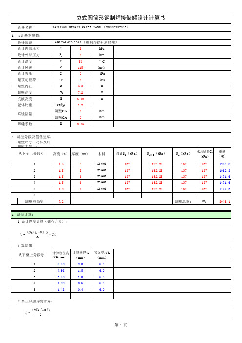
设备名称设计规范:设计内部压力P i 8kPa 设计外部压力P e 0kPa 设计温度T 50°C 设计风速V 115km/h 设计雪压S 0 kPa 罐顶动载荷Lr 0 kPa 罐壁内径D 6.5m 罐壁高度 H 17.2m 充液高度H 6.48m液体比重G 或ρ 1.2罐壁CA 0mm 罐底CA 0mm 焊缝系数E0.85罐壁尺寸、材料及许用应力如下:高度(m)厚度(mm)材料设计S d (MPa )R p0.2(MPa )R m (MPa )水压试验S t (MPa)重量(kg )1 1.58S30408137192.251371371962.82 1.58S30408137192.251371371962.83 1.56S30408137192.251371371471.64 1.56S30408137192.251371371471.65 1.26S30408137192.251371371177.36罐壁总高度7.2罐壁总重:m 18046.1计算结果:计算液位高度H (m )计算壁厚t d (mm )名义厚度t n(mm )1 6.48 2.0 6.02 4.98 1.5 6.03 3.48 1.0 6.04 1.980.6 6.051.480.46.0立式圆筒形钢制焊接储罐设计计算书从下至上分段号TAILINGS DECANT WATER TANK (2020-TK-003)从下至上分段号1. 设计基本参数:API Std 650-2013 《钢制焊接石油储罐》2) 水压试验厚度计算:2. 罐壁分段及假设壁厚:腐蚀裕量3. 罐壁计算:1) 设计厚度计算(储存介质):罐壁高度度: H1—中间抗风t—除非另有规定,量宽度的那层壁板的。
大型立式储罐计算解读

六、重要参数释义(续)
2)罐顶计算厚度还应乘设计温度与常温下钢材的弹性模量之比 3)抗风计算中,罐壁的许用临界压力应乘设计温度与常温下钢材 的弹性模量之比 4)微内压储罐设计压力公式中系数1.1还应乘设计温度下材料的 屈服强度与210MPa的比值(不得大于1) 5)有保温的锚栓的许用应力应为常温下许用应力乘以表2.2(P22) 设计温度下屈服强度降低系数 3.许用应力如何选取:碳钢和低合金钢可直接按GB50341查取, 高合金钢许用应力确定按SH3046-1992查取,不能用GB150中数 值。 4.焊接系数:一般取0.9,当标准规定的最低屈服强度大于390MPa时 取0.85, 储存极度和高度危害的介质时,天辰取1.0 5.直径范围:公称直径5m<DN<32m,公称直径小于等于5米常压 储罐一般不用计算。
八、罐壁计算模块(续)
罐壁名义厚度不得小于计算厚度加壁厚附加量的较大 值,且不得小于表6.3.3规定值(P27)。由于罐壁高度通 常大于钢板宽度,所以罐壁总是用多圈钢板组焊而成; 壁厚从下向上逐层递减,相邻壁厚差最好不超过2mm; 底圈壁板是产生周向拉应力及纵向弯曲应力最大部分, 所以有意将底圈壁板加厚。 2) 判别设置中间抗风圈数量、位置步骤: A.核算区间的罐壁筒体许用临界压力Pcr B.计算存在内压的固定顶油罐罐壁筒体的设计外压Po C.判断中间抗风圈数量、位置(P33-6.5.4) 注意:天辰计算程序只给出一个中间抗风圈位置,当 需设两个以上数量时,设置位置按标准具体给出。
十、罐顶计算模块(续)
加强肋计算 拱顶有效厚度 经向肋的厚度 trn-cr1-cr2 mm mm th b1 6.2 5.7
纬向肋的厚度
经向肋的宽度 纬向肋的宽度 经向肋的最大间距 纬向肋的最大间距 经向带肋组合截面型心到顶板中心面的距离 纬向带肋组合截面型心到顶板中心面的距离 经向带肋截面的面积折算系数 纬向带肋截面的面积折算系数 经向带肋截面平均抗弯刚度值 纬向带肋截面平均抗弯刚度值 壳板抗弯刚度值 带肋拱顶的折算厚度 带肋拱顶许用临界压力 罐顶设计外压 **********校核合格********** 0.1*Et(tm/Rs/1000)2(th/tm)0.5
PVA650手册
PathMaster® Manual Warnings, Cautions, and NotesCertain warning symbols are affixed to the machine and correspond to notations in this manual. Before operating the Dispensing System, identify these warning labels and read the notices described below. Not all labels may be used on any specific system.Always wear approved safety glasses when operating or working near theDispensing System.6040In situations where inattention could cause either personal injury ordamage to equipment a warning notice is used.6014Do not smoke near the Dispensing System. Always have a fireextinguisher available for emergency use.6019Before operating the system, read and understand the manuals providedwith the unit.6017Before performing any repairs or maintenance to the system, turn offpower and lock out the power disconnect switch.6011Never place hands or tools in areas designated by this symbol when themachine is in operation. A dangerous condition may exist.6008Warning notices are used to emphasize that hazardous voltages, current, temperatures, or other conditions that could case personal injury exist in this equipment or may be associated with its use. Only qualified personnel should enter areas designated with this symbol.6010Before performing any repairs or maintenance to the system, read and understand the manuals provided with the unit. Service should only be performed by a qualified individual.6018Exercise caution when pressurized vessels are present. Identify and repair any leaks immediately. Always wear appropriate safety equipment when working with pressurized vessels or vessels containing chemicals. 6054Laser light source present. Do not stare directly into the beam. Do not use in the presence of highly reflective surfaces.6003Pinch hazard from moving parts. Avoid contact.1012Shear hazard from moving parts. Avoid contact.1099Hot surface. Avoid contact.6043Do not remove protective guarding.6060This document is based on information available at the time of its publication. While efforts have been made to be accurate, the information contained herein does not purport to cover all details or variations in hardware or software, nor to provide for every possible contingency in connection with installation, operation, or maintenance. Features may be described herein which are not present in all hardware and software systems. Precision Valve & Automation, Inc. assumes no obligation of notice to holders of this document with respect to changes subsequently made.Precision Valve & Automation, Inc. makes no representation or warranty, expressed, implied, or statutory with respect to, and assumes no responsibility for the accuracy, completeness, sufficiency, or usefulness of the information contained herein. No warranties of merchantability or fitness for purpose shall apply.This document, including the information contained herein, is the property of Precision Valve & Automation, Inc. and is considered confidential and proprietary information. It is delivered on the express condition that it not be used, disclosed, or reproduced in whole or in part, for any reason without prior written consent of Precision Valve & Automation, Inc.Copyright © 2003 Precision Valve & Automation, Inc.All Rights Reserved.PrefaceNotice & DisclaimerThis manual applies to one of the following automated workcells produced by Precision Valve & Automation, Inc.:•PVA250™•PVA550™•PVA750™•PVA1000™•PVA2000™•PVA200C™•PVA3000™All machines are referenced throughout the manual as the Dispensing System or Workcell. This manual provides information and functionality descriptions covering all the common options and configurations for a Dispensing System. The particular machine associated with this manual may not contain all items or may have additions. If the manual refers to an option that was not purchased, ignore that section. If options exist on the machine not mentioned in this manual, please consult the Optional Equipment section of the Operating Guide for more information on these additions.Revisions to This ManualThe following list describes the major revisions in this manual (Rev. H 6/03) as compared to previous manuals:•Rewrite for PathMaster® version 2.05, including subroutine information.•Update for PathMaster® version 2.3. 6/23/03 TMBContent of This ManualDefinitions. Definitions for commonly used terms.Notices and Warning. Basic safety practices are reviewed.Getting Started. Instructions on establishing communication with the Dispensing System and installing the PathMaster® software.Working with Materials. Overview on the basics of liquid dispensing.Beginning Programming. Prerequisite information for using PathMaster®.PathMaster® Overview. Basic description of features and tools of PathMaster® software.Using PathMaster®. Detailed manual on using the PathMaster® software.DMC Error Code. A list of error codes that may be encountered while using the Dispensing System.ContentsTable of Contents Preface (iv)Notice & Disclaimer (iv)Revisions to This Manual (iv)Content of This Manual (iv)Contents (v)Table of Contents (v)List of Tables (viii)Definitions (9)Notices and Warnings (11)Getting Started (12)Necessary Skills (12)Hardware & Software Requirements (12)Installing PathMaster® (12)Tutorials (12)Communications (12)DMC-1500 Dip Switch Settings (12)Computer Settings (13)Uninstalling PathMaster® (13)Multiple Dispensing System Issues (13)Year 2000 Compliance (13)If Something Goes Wrong . . (14)Calling Technical Support (14)Working with Materials (15)Overview (15)System Components (15)Material Feed (15)Dispense (Needle) Valve (15)Spray Valve (15)Programming (16)Beginning Programming (17)Overview (17)Planning Path Programs (17)Incorrect Valve Usage (17)Inserting Valve Commands into Programs (17)Inter-Path Movement (18)Main Program Modifications (18)Common Main Program Changes (18)PathMaster® Overview (20)General (20)PathMaster® Window (20)Upper Status Bar (20)Lower Status Bar (20)File Menu (21)Edit Menu (21)Teach Menu (21)Modify Menu (21)Run Menu (22)Download Menu (22)Utilities Menu (22)Setup Menu (22)Help Menu (22)Right-Click Menu (22)Teach (22)Modify (23)Run (23)Programming Toolbar (23)Programming Tools (23)PathMaster® Database (24)General (24)Multiple Dispensing Systems (24)Machine Configuration (24)Path Programs (24)Project Files (24)Using PathMaster® (25)Starting PathMaster® (25)Configuring PathMaster® (25)Machine Parameters (25)Database Backup and Restoration (29)Automatic Backup (29)Manual Backup (29)Database Restoration (30)Important Reminders (30)Machine Selection (30)Project Selection (31)Reading a Program (31)Playback (32)Edit Windows (32)Interacting With the Dispensing System (33)Manual/Jog/Teach Mode (33)Trackball Control (33)Teach Pendant (34)OIT Jog Control (35)TracMouse™ (36)Pneumatic Commands (36)Programming Tools (36)Adding Comments (36)Move (37)2D Path (38)3D Path (39)Arc (40)Circle (41)Area (42)PolyLine (46)Dot (47)Head (49)Step Over (49)Dwell (50)Subroutine (50)I/O (52)DMC Command (53)Valve Offsets (53)Offline Programming (FastPath™) (56)Setting Up the Image (56)Valve Selection (56)Drawing a Program (57)Commands (58)Move (58)Head (58)2D Line (58)Arc (58)Circle (58)Area (58)FastMask™ (58)Dot (59)Editing the commands (59)Password Protection (59)Download Password (59)Save Password (59)Changing Password (59)Resetting Password (59)Importing Files (60)CAD Files (60)PathMaster® 1.5 & Pre 1.5 Projects (64)Text File (64)DMC File (64)Subroutine (64)Exporting Files (64)Text File (64)DMC File (64)Subroutine (65)Utilities (65)View FastPath (65)Measure Distance (65)Machine Debugger (65)Refresh Communication (73)Jog Toolbar (73)Path Preview (73)Show Code (73)DMC Error Codes (74)List of TablesTable 1 – DMC-1500 Dip Switch Settings for PathMaster® (12)Table 2 – Communication Program Settings (13)Table 3 – Coordinate System Locations (19)Table 4 – Variable Explanations (19)Table 5 - Required CAD File Elements (60)Table 6 – Important DMC Commands (67)Table 7 – DMC Error Codes (74)DefinitionsAuto Cycle – Machine state where cycles are running.Auto Purge – A machine function that automatically purges material after a predefined period of time. Calibration Position – The location in the workspace where the X, Y, Z and W locations for the needle(s) is normalized.Cycle Stop – Machine state where no action is occurring and the machine is at the standby position. Depress – Press and hold for the duration of the operation.Dispense Path – A continuous motion profile. The valve is on (dispensing or spraying) during the entire motion profile. Also known as a Path or Motion Sequence.DMC – Language used to program the motion controller in the Dispensing System.End Effector – The dispense head assembly. The end effector is moved by the axes.Head – Dispensing, or spray valve (or any other part processing device).Home Position – The (0, 0, 0, 0) location of the workspace. This position is determined by the location of the home sensors. It is NOT the same as the Standby Position.Jog – One or more axes are command to traverse continuously at a specified speed until commanded to stop.Light Tower – The light tower consists of three stacked lights, red, amber and green (top to bottom). It is used to indicate the status of the machine.Main program file – Text file containing the code that runs the Dispensing System during normal operations.Motion Sequence – A continuous motion profile. The valve is on (dispensing) during the entire motion profile. Also known as a Dispense Path, Coating Path or Path.Offline Programming - A manor of programming Path Programs without being connected to the Dispensing System. Known as FastPath™.Path – A continuous motion profile. The valve is on (dispensing) during the entire motion profile. Also known as a Dispense Path or Motion Sequence.PathMaster® – Windows® programming software. Used to create, maintain and download program files for the Dispensing System.Press – Press and release.Program – A collection (or series) of motion sequences.Project – File containing the code for one or more programs.Purge Position – The location in the workspace where the head moves to perform all auto purge operations.PVA – Precision Valve & Automation, Inc. Precision Valve & Automation.Solvent Cups – A container filled with an agent designed to prevent the spray and dispensing valves from clogging when idle for a specified period of time. Also known as Solvent Rest.Solvent Purge – An Auto Purge performed after the valves move from the solvent cups prior to processing product.Standby Position – The rest position for the end effector. The machine moves here after homing and after each cycle. This position is usually located near the start point for the program(s). It is NOT the same as the Home Position.Terminal – A program used as a communication link between the controller and operator.WSDK-1500 – Windows® Servo Design Kit 1500. This software is used to setup and tune the servo system.Notices and Warnings•Safety glasses, gloves, and long sleeved clothing are necessary precautions when working with automated industrial equipment.•Read and understand all operating manuals before using this equipment.•Do not disable the safety features of the machine.•Lock-out and tag the air and power supplies before servicing or cleaning any part of this equipment. •Do not remove any hose, either air or fluid, without relieving the pressure.•Do not replace any hose with a hose of inadequate pressure rating.•Use only replacement parts recommended or supplied by the manufacturer.•Always remain clear of all moving parts when the system is in operation.Getting StartedNecessary SkillsThe Dispensing System operator must be familiar with Windows® and its most common features. This includes Notepad (or a similar text editing program), Explorer (or File Manager) and how to cut-and-paste information from one place to another. It is STRONGLY recommended that personnel be thoroughly versed in these subjects before attempting to program the machine.Hardware & Software RequirementsPathMaster® requires a Pentium processor and at least 32 MB of RAM for Windows® 95, 98, NT, 2000, me, or XP operating systems.Installing PathMaster®To install PathMaster®, first close any applications that may be open. If the install is done via 3½” disks, take disk #1 of the PathMaster® installation disks and place it in the floppy drive, making sure it is secure. Run setup.exe and follow the instructions on the screen. For CD-ROM installations, insert the CD into the CD drive. Run setup.exe on the CD drive and follow the instructions on the screen.NOTE: PVA recommends installing the software in its default directory (c:\Program Files\PVA).TutorialsIn the tutorials directory of the PathMaster® CD-ROM are a number of audio/visual tutorials. These can be accessed via the Help→Contents option in PathMaster® or the pathmaster.hlp file.NOTE: If the computer in use does not have a sound card or the card is not installed properly, the audio portion of the tutorials will not function.CommunicationsThe Dispensing System communicates with a computer using the EIA RS-232C standard. The computer is the Data Terminal Equipment (DTE Device) and the controller is the Data Communications Equipment (DCE Device). A programming port is located on the front of the machine. The controller baud rate and handshaking function are set with dip switches on the controller inside the Dispensing System enclosure. The settings for the controller and the computer must be the same.WARNING The computer must be at the same ground potential as the machine. Damage tothe machine or computer may result if the ground potentials are different. Use the Dispensing System service outlet for computer power.DMC-1500 Dip Switch SettingsThe main RS-232 port on the DMC-1500 controller must be configured as follows to communicate with the PathMaster® software.Table 1 – DMC-1500 Dip Switch Settings for PathMaster®Switch Position DescriptionMRST OFF MasterSwitchResetrate1200 OFF Baud9600 ON Baudraterate19200 OFF BaudHSHK ON Hardware Handshaking SwitchNOTE: If hardware handshaking is enabled, and the program uses the message command and a computer is not attached to the Main RS-232 port, the controller eventually halts. A computer must be attached to the controller when handshaking is enabled and message commands are used.Computer SettingsThe following are the correct settings to communicate with the motion controller. PathMaster®automatically sets the data bits, parity and stop bits.Table 2 – Communication Program SettingsOption SettingBaud rate 9600Data bits 8Parity noneStop bits 1Uninstalling PathMaster®To uninstall the software go to Windows®Control Panel and select Add/Remove Programs. The Install/Uninstall screen appears. Scroll down and highlight PathMaster. Then click on the Add/Remove button. PathMaster® is removed by Windows®.As Windows® removes all the components associated with PathMaster®, it may query the operator concerning shared files. If in doubt, Precision Valve & Automation, Inc. recommends NOT deleting any shared files. Precision Valve & Automation, Inc. assumes no responsibility for any difficulties arising from the deletion of shared files during the uninstall procedure of PathMaster®.NOTE: This process completely eliminates the PathMaster® software and all its components, including registry entries.Multiple Dispensing System IssuesUnless a multiple machine cross-programming system was purchased with the Dispensing System, Precision Valve & Automation, Inc. Precision Valve & Automation STRONGLY recommends that customers not attempt to run programs developed with one Dispensing System on a second Dispensing System. While machines may appear similar, minor differences in the homing sequence, pneumatic actuators, etc. can be sufficient to cause an externally-developed program to damage a Dispensing System. Precision Valve & Automation, Inc. is not responsible for damages incurred in any such attempt.Year 2000 CompliancePathMaster® is compliant with and comprehends the year 2000 century date change. PathMaster® will not have any operational impediments, malfunction, cease to perform, generate incorrect or ambiguous data and/or produce incorrect or ambiguous results with respect to same-century and multi-century formulas, functions, date values and date-data interfaces.If Something Goes Wrong . . .Some problems encountered when using the Dispensing System are easy to identify and solve. Others require more extensive help. It is best to program in small increments, so problems appear quickly and can be diagnosed easily. Save work frequently during the programming process.For non-immediate problems or to report suggestions, please email pathmaster@.Calling Technical SupportThe technical support staff is always available to help solve any problems. The phone number is (518) 371-2684. To assist in the troubleshooting process, it is best if as many of the following items are addressed before calling for help:1) Note the serial number of the Dispensing System. The serial number can be found on the legend platelocated on the front of the electrical enclosure.2) Record all the information on the OIT or PC when the error occurred.3) If the error was not serious, attempt to repeat the error. If the error does not repeat, the problem mayhave been operator generated.4) Use a terminal screen to communicate with the controller. Most troubleshooting requires issuingcommands directly to the controller.5) A hard copy or email of the program in question may be requested by PVA. Please be prepared tosend it. The PVA fax number is (518) 371-2688, or the customer service representative will provide an email address, if all parties are email capable.Working with MaterialsOverviewThe Dispensing System workcell is designed to operate with many different materials in a variety of applications. Learning to use and program with these materials is both an art and a science. There are no concrete rules for an operator to follow; the best method for establishing settings for the system is trial-and-error. Once acceptable parameters are found it is easy to maintain those parameters over time.System ComponentsEach part of the material delivery system must be adjusted and optimized for the selected material. In general, it is best to approach the problems in the order listed below.Material FeedUsually, material is moved through the system by one of two methods, either a pump or a pressure vessel. For either method, the operator’s first task is to consult the manufacturer’s material specifications and determine the appropriate settings for the material delivery system. If a pump is used on the system, the separate pump manual should be thoroughly read and understood to determine the best settings for the material. For a pressure vessel, if the pressure is too high the valve output will be excessive and inconsistent in flow and air may be forced into the material. Too little pressure provides insufficient output.Dispense (Needle) ValveThe only direct adjustment for the needle valve is the stroke. Turning the knurled knob on the top of the valve counter-clockwise increases flow through the valve. A fine steady stream of material is all that is needed. Once a satisfactory setting is found, secure the stroke position with the locking nut. Once the locking nut is secure verify the valve flow rate before continuing.Needle SelectionExperiment with different needle sizes to determine the best size for the system. If the needle is too large a drip develops at the end of the needle. To small a needle yields insufficient flow.Spray ValveTwo adjustments are available for the spray valve: Valve stroke and atomizing air. The stroke controls the flow of material through the valve. Turning the knurled knob on the top of the valve counter-clockwise increases flow through the valve. Atomizing air is controlled by a pressure regulator located on the front of the machine. Turning this clockwise increases the air pressure. This pressure can only be adjusted while the valve is active. Once satisfactory settings are found for these items, secure the stroke position on the valve using the locking nut. Secure the regulator by pressing the cap or tightening the lock nut. Once the locking nut is secure verify the valve flow rate before continuing.When first operating the machine, follow this list of instructions to adjust the spray valve:1) Set the atomizing air to 0 P.S.I.2) Take off the spray cap.3) Turn the stroke down all the way.4) Using the purge function in Manual mode, open the stroke to a few drops per second. It may benecessary to cycle the valve on and off while adjusting the stroke.5) Replace the spray cap.6) While purging, adjust the atomizing air until the spray is satisfactory. Test the spray pattern on scrap. If the atomizing air is too high, the spray will be misty. If it is too low, there will be splatter. Thin, solvent based materials usually require as little as 0.5 P.S.I., while some silicones require as much as 15 P.S.I.Extended Spray CapThis cap is exclusive to the FCS100-ES valve. It is identified by its small long cylinder nozzle. This cap can reach into tight areas between tall components, were a very defined pattern is required.Round Spray CapThis provides a circular spray pattern. It is identified by its lack of external air ports. It works well for solvent based materials or where a smaller, more defined pattern is required.Flat Spray CapThe spray from this cap is rectangular/oval in shape. It is identified by the protruding atomizing air ports. It works best with non-solvent based materials and provides a wider spray path for increased coverage. ProgrammingOnce the physical parameters are successfully established for the delivery system, they should never be altered. The best method for changing the material output is to alter the program. In most cases, raising or lowering the speed of a dispense path is enough to change the material output to the desired level.When programming with the dispense valve, lower the valve so that the end of the needle is close to the part surface, but not too close such that varying needle length tolerances will cause the needle to make contact with the surface of the product.With the spray valve, a good rule of thumb is to start about ¾” (19 mm) above the product surface. With atomizing air, this should produce a spray width approximately ½” to ¾” (19 mm) wide. If necessary, adjust the spray height so the pattern on the product is consistent and uniform.Beginning ProgrammingOverviewThis section provides important information every operator must know before programming the Dispensing System. A thorough understanding is recommended.Planning Path ProgramsIt is best to plan the path program on paper before starting on the machine. Break the planned program into individual paths and number each path and the points within it, along with which valve is active and what pneumatic operations must be performed. The path numbers and point numbers should correspond to the order in which the program proceeds. This documentation is very useful when debugging programs. Breaking the path program into smaller segments is wise and provides three advantages. First, each segment can have different on, off and speed parameters. Second, the operator can focus on programming and debugging one segment at a time. Third, if one segment of the program must be changed, the remaining segments are not affected. This reduces debugging time and makes the program maintainable. When programming, the operator should comment the program as needed to enable anyone to follow the logic. Again, this decreases debugging problems and saves time in the long run.NOTE: If a stop or dwell must be added at one of the points after a path is completed, then the path must be broken into two paths or entirely reprogrammed.Incorrect Valve UsageWhen programming or operating the Dispensing System, the valves should NEVER be used for moving components or boards. Precision Valve & Automation is not responsible for damages incurred from using the valves in an inappropriate manner.Inserting Valve Commands into ProgramsPneumatic positions (head up/down, rotary selection) are not automatically programmed by PathMaster®and there is no communication between the Dispensing System and PathMaster® concerning the active valve or its pneumatic position. Therefore, it is the responsibility of the operator to select the appropriate valve within PathMaster® and insert the necessary pneumatic commands into the program after a path has been completed.It is important these commands are not inserted at incorrect locations. In general, try to follow these rules: •Program each segment with the corresponding valve slide in the down position.•Actuate a valve rotary before lowering a valve slide.•Move the XY(W) axes into position prior to actuating a valve slide or valve rotary.•Insert valve slide down and valve rotary B commands before any segment(s) that require them. •Insert valve slide up and rotary A commands once finished with the valve.•Raise a valve slide before returning a rotary to A.•Insert all the code for each segment after completing it.•If suddenly changing valves, insert a non-dispense move on the Z axis to 0, to allow room for the new valve to lower. (See Inter-Path Movement on page 18 for more detail.)Inter-Path MovementWhen programming the Dispensing System via PathMaster® it is easy to determine the movement, point-to-point, within a path program via the playback feature. However, it is more difficult to gauge movement between segments. After completing a segment, the Dispensing System immediately moves the axes to the start point of the next segment. If there are obstacles in the way, the machine does not know this, since this route was not tested and programmed intentionally.There are different ways to combat this problem. The best solution is to follow the recommended procedure and map out the path program to allow for direct movements between segments. If that was not done, or obstacles cannot be avoided, then the operator should insert ‘safety’ moves of the Z axis to avoid inadvertently hitting anything. This is accomplished by programming a ‘Z only’ move, with the Z-axis target set to 0.It is ultimately the operator’s responsibility to ensure no combination or sequence of path segments are harmful to the machine or any product the operator is running.Main Program ModificationsSometimes it is necessary to make changes in the main program that runs the Dispensing System. Usually it involves setting up points for the machine to use. If the operator must do this, it is imperative to download the corrected main file properly to avoid any problems. Open the Main program using a text editor, such as Windows® Notepad or Winpad.Common Main Program ChangesThere are a few sets of points that commonly need changing: Standby position, purge position, solvent cup position, and calibration position. In the main program these settings are located in the Machine Specific Information section (near the end of the file), an example of which is shown below:REM!!!!Machine-Specific Information!!!!#IMACH;MT1,1,1,1CE0,0,0,0;FSTX=20000;SLWX=10000;FSTY=20000;SLWY=10000FSTZ=10000;SLWZ=5000;FSTW=10000;SLWW=5000KNHEAD=3;A_HEAD[1]="FCS100";R_HEAD[1]=0A_HEAD[2]="FC100";R_HEAD[2]=1A_HEAD[3]="DISPSE";R_HEAD[3]=1PT_APG[0]=80000;PT_APG[1]=65000;PT_APG[2]=0;PT_APG[3]=3000PT_SOL[0]=80000;PT_SOL[1]=65000;PT_SOL[2]=0;PT_SOL[3]=3000PT_CAL[0]=15000;PT_CAL[1]=15000;PT_CAL[2]=500;PT_CAL[3]=2000PT_SBY[0]=25000;PT_SBY[1]=25000;PT_SBY[2]=250;PT_SBY[3]=3500AP_EN=0;AP_LEN=2000;AP_TIME=30000;PNTO=4000;LT_EN=1;AC_TMR=1SLP_TM=30000;SO_EN=0;LLA_EN=0;LLB_EN=0#TUNE;AC*=325000;DC*=300000;SP*=120000;VA*=70000;VD*=70000BL-4000,-4000,-1000,-1000FL83000,85000,15000,30000;TL*=9.9999KD67.99,82.43,76.09,50.00KP 5.66,6.75,8.38,5.00KI0.25,0.19,0.34,0.50;EN。
施耐德 APCBack-UPS 650 230 数据表
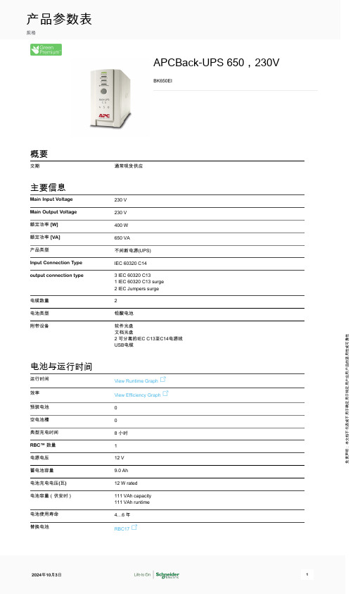
APCBack-UPS 650,230VBK650EI概要交期通常现货供应主要信息Main Input Voltage230 VMain Output Voltage230 V额定功率 [W]400 W额定功率 [VA]650 VA产品类型不间断电源(UPS)Input Connection Type IEC 60320 C14output connection type 3 IEC 60320 C131 IEC 60320 C13 surge2 IEC Jumpers surge电缆数量2电池类型铅酸电池附带设备软件光盘文档光盘2 可分离的IEC C13至C14电源线USB电缆电池与运行时间运行时间View Runtime Graph效率View Efficiency Graph预装电池0空电池槽0典型充电时间8 小时RBC™ 数量1电源电压12 V蓄电池容量9.0 Ah电池充电电压(瓦)12 W rated电池容量(伏安时)111 VAh capacity111 VAh runtime电池使用寿命4…6 年替换电池RBC17产品参数表规格免责声明:本文档不代表或不用于确定用于特定用户应用产品的适用性或可靠性电池图评论此图是基于实际测量的运行时间数据。
所有测量均采用新的、完全充满电的电池和平衡电阻负载(PF = 1.0)进行。
实际运行时间可能会与此图所示值有所不同。
实际运行时间依赖于几个变量,包括电池使用时间、电池的充电量、环境条件和所连接负载的特性。
可自动检测、可扩展的延时时间0通用空闲功率模块插槽数量0已填充功率模块插槽数量0冗余No物理参数颜色灰色高度16.5 cm宽度9.1 cm深度28.4 cm净重 6.03 kg安装位置正面安装偏好No preference安装类型Not rack-mountable可安装在双柱上0USB 兼容Yes输入网络频率47...63 Hz50/60 Hz +/- 3 Hz auto-sensing输入电压限制160...286 V 可调180...266 V最大输入电流7 A开关电流能力7 A输出最大可配置功率(瓦)400 W输出频率(与主频率同步)47...63 Hz 与主频率同步50/60 Hz +/- 1 Hz 不同步拓朴备用波形类型正弦波逐步逼近最大可配置功率(伏安)650 VA转换时间一般 0.6 秒:最多 1 秒相符性产品认证A- 垫套C-TickCEGOSTNEMKO符合标准EN/IEC 62040-1:2019/A11:2021EN/IEC 62040-2:2006/AC:2006EN/IEC 62040-2:2018环境运行温度0…40 °C相对湿度5…95 %工作海拔0...10000 ft贮存环境温度-15…45 °C存储相对湿度5…95 %存储高度0.0000000000…15240.0000000000 m声响级别45 dBA通讯与管理控制面板LED status display with on line : on battery : replace battery and overload indicators警报Alarm when on battery : distinctive low battery alarm : overload continuous tonealarm浪涌保护及滤波浪涌抑制能量310 J包装单位Unit Type of Package 1PCENumber of Units in Package 11Package 1 Height49.400 cmPackage 1 Width18.500 cmPackage 1 Length41.500 cmPackage 1 Weight7.310 kgUnit Type of Package 2PAMNumber of Units in Package 235Package 2 Height132.500 cmPackage 2 Width100.000 cmPackage 2 Length120.000 cmPackage 2 Weight267.850 kgSCC1410731304219788合同保修保修单2年内维修或更换可持续Green Premium TM 标签 是施耐德电气致力于提供具备一流环保性能的产品的承诺。
Texas Instruments TPS65020EVM-110 评估模块用户指南说明书
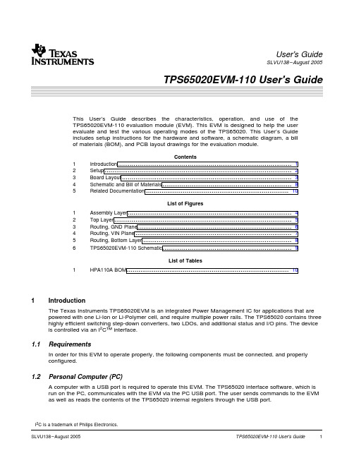
1Introduction1.1Requirements1.2Personal Computer (PC)User's GuideSLVU138–August 2005This User’s Guide describes the characteristics,operation,and use of the TPS65020EVM-110evaluation module (EVM).This EVM is designed to help the user evaluate and test the various operating modes of the TPS65020.This User’s Guide includes setup instructions for the hardware and software,a schematic diagram,a bill of materials (BOM),and PCB layout drawings for the evaluation module.Contents1Introduction ..........................................................................................12Setup .................................................................................................23Board Layout ........................................................................................34Schematic and Bill of Materials . (85)Related Documentation (10)List of Figures1Assembly Layer .....................................................................................42Top Layer ............................................................................................53Routing,GND Plane ................................................................................64Routing,VIN Plane .................................................................................75Routing,Bottom Layer .. (86)TPS65020EVM-110Schematic ...................................................................9List of Tables1HPA110A BOM (10)The Texas Instruments TPS65020EVM is an integrated Power Management IC for applications that are powered with one Li-Ion or Li-Polymer cell,and require multiple power rails.The TPS65020contains three highly efficient switching step-down converters,two LDOs,and additional status and I/O pins.The device is controlled via an I 2C™interface.In order for this EVM to operate properly,the following components must be connected,and properly configured.A computer with a USB port is required to operate this EVM.The TPS65020interface software,which is run on the PC,communicates with the EVM via the PC USB port.The user sends commands to the EVM as well as reads the contents of the TPS65020internal registers through the USB port.I 2C is a trademark of Philips Electronics.1.3Printed Circuit Board Assembly1.4USB to I 2C Interface Board (EV2300)1.5Software2Setup2.1Input /Output Connector DescriptionsSetupThe TPS65020EVM-110PCB contains the TPS65020IC and its required external components.This board contains several jumpers and connectors that allow the user to customize the board for specific operating conditions.The EV2300is the link that allows the PC and the EVM to communicate.One end of the EV2300connects to the PC with the supplied USB cable,and the other end of the EV2300connects to the EVM with the supplied Molex cable.When the user writes a command to the EVM,the interface program,which is run from the PC,sends the command to the PC USB port.The EV2300receives the USB command and converts the signal to an I 2C protocol.It then sends the I 2C signal to the TPS65020board.When the user reads a status register from the EVM,the PC sends a command to read a register on the EVM.When the EVM receives the command,it reports the status of the register via the I 2C interface.The EV2300receives the information on the I 2C interface,converts it to a USB protocol,and sends it to the PC.Texas Instruments has provided software to assist the user in evaluating this EVM.To install the software,insert the enclosed CD into your computer.The software should start automatically.If it does not,simply go to <Start>,<Run>,and type “D:\SLVU138.exe”,and click <OK>(assuming that D:is your CD drive).The program should run without errors.If any problems occur that result in the program not beinginstalled,view the readme.txt file on the CD for further information.Check the TPS65020product folder on the TI website for the latest revision of the software.This section describes the jumpers and connectors on the EVM as well as how to properly connect,setup,and use the TPS65020EVM-110.INPUT /OUTPUTDESCRIPTIONInput voltage from external power supply,recommended maximum 5.5V.Input current is dependent J1–VIN on load but is typically below 2A.J2–GND This is the return connection for V I .Input voltage and return for LDO1and LDO2C.Resistor R23connects this pin to VDCDC1.If an J3–VINLDO/GND external power supply is used,remove R23.Recommended maximum input voltage is 5.5V Input voltage and return for VSYSIN,one of the input voltages for RTC.Resistor R24connects this J4–VSYSIN/GND input to VDCDC1.If an external power supply is used,remove R24.Recommended maximum input voltage is 4VInput voltage and return for VBACKUP,one of the input voltages for RTC.There is no on board J5–VBACKUP/GND connections to a voltage input.Recommended maximum input voltage is 4V.Direct connection to the GPIO1and GPIO2pins.For this EVM,GPIO1is configured as a J6–GPIO1/GPIO2push-button input,and GPIO2is configured as an LED output.J7–VRTC/GNDOutput voltage from the RTC circuit.Four fault outputs are available on this connector:PWRFAIL -Fault occurs when input voltage is below 3V.Pulled up to VRTC when safe,low for fail.INT -Fault occurs when there is a fail on an input or output voltage.It acts as a sum fail.Pulled up J8–Fault Outputsto V I when safe,low for fail.RESPWRON–Low reset signal controlled by SW2,300mS.Pulled up to V I normally.LOWBAT–Fault occurs when input voltage is below 3.6V.Pulled up to V I when safe,low for fail.J9–USB This header duplicates the signals from the J20interface connector.Output from DCDC1switching regulator,maximum output current is 1.2A,default voltage setting is J10–VDCDC13.3V.2.2Setup3Board Layout Board LayoutINPUT/OUTPUT DESCRIPTIONJ11–GND Return for VDCDC1J12–VDCDC2Output from DCDC2switching regulator,maximum output current1A,default voltage setting2.5V.J13–GND Return for VDCDC2J14–VLDO1Output from the low drop out regulator VLDO1,maximun current out is50mA,default value1.1V.J15–GND Return for VLDO1J16–VLDO2Output from the low drop out regulator,VLDO2maximum current out is50mA,default value1.3V.J17–GND Return for VLDO2J18–VDCDC3Output from the switching regulator DCDC3,maximum current is800mA,default value1.55AJ19–GND Return for VDCDC3J20–USB USB interface connectorJP1–DEF1Sets voltage for DCDC1to3V or3.3V.JP2–DEF2Sets voltage for DCDC2to2.5V or1.8V.JP3–DEF3Sets voltage for DCDC3to1.55V or1.3V.JP4–DCDC1ON/OFF EN for regulator DCDC1,default setting is ON.JP5–DCDC2ON/OFF EN for regulator DCDC2,default setting is ON.JP6–DCDC3ON/OFF EN for regulator DCDC3,default setting is ON.JP7–LDO ON/OFF EN for both LDO1and LDO2regulators,default setting is ON.S1is a normally open momentary push-button switch that,when pressed,connects V I to GPIO1.S1–GPIO1The GPIO1input is configured on the TPS65020as a debounced push button that drives anON/OFF circuit with output at GPIO2.S2is a normally open momentary push-button switch that,when pressed,connects the HOT_RST S2–HOT_RST input of the TPS65020to GND generating the Hot_Reset pulse.The HOT_RST pin is externallypulled up.The following steps must be followed before the EVM is operated1.Install the TPS65020EVM Software.2.Connect input voltages and loads to the EVM.3.Configure all EVM jumpers to factory setting.–JP4—ON–JP1—3.3V–JP3—1.55V–JP2—2.5V–JP5—ON–JP6—ON–JP7—ON4.Connect the Molex cable between the EVM and the EV2300.Note that the Molex cable must connectto the I2C connector on the EV2300.5.Connect the USB cable between the computer and the EVM.6.Turn on all supplies and loads.7.Run the TPS65020EVM software.This section provides the TPS65020EVM-110board layout and illustrations. Board Layout3.1LayoutBoard layout is critical for all switch mode power supplies.Figure1through Figure5show the boardlayout for the TPS65020EVM-110PWB.The nodes with high switching frequencies and currents are short and are isolated from the noise sensitive feedback circuitry.Careful attention has been given to the routing of high frequency current loops.See to the datasheet for specific layout guidelines.Figure1.Assembly LayerBoard LayoutFigure2.Top Layer Board LayoutFigure3.Routing,GND PlaneBoard LayoutFigure4.Routing,VIN Plane Schematic and Bill of MaterialsFigure5.Routing,Bottom Layer4Schematic and Bill of MaterialsThis section provides the TPS65020EVM-110schematic and bill of materials.Schematic and Bill of Materials 4.1SchematicFigure6.TPS65020EVM-110Schematic4.2Bill of Material5Related DocumentationRelated DocumentationTable 1.HPA110A BOMCount Ref DesValueDescriptionSizePart No.MFR–001–002C1,C2,C4,C9,99C10,C11,10µF Capacitor,ceramic,10µF,6.3V,X5R,20%0805C2012X5R0J106K TDKC14,C15,C16C8,C12,44 2.2µF Capacitor,ceramic,2.2µF,6.3V,X5R,10%0603C1608X5R0J225K TDK C13,C18C3,C6,44 1.0µFCapacitor,Ceramic,1.0µF,6.3V,X5R,10%0603C1608X5R0J105KTDKC7,C1711C51500pF Capacitor,Ceramic,1500pF,50V,X7R,10%0603C1608X7R1H152K TDK Diode,LED,Red,Gullwing,GW Type,20ma,11D1Red 0.087x 0.120LN1261CALPanasonic1.4mcd typDiode,LED,Red,Gullwing,GW Type,20ma,00D2Open0.087x 0.1201.4mcd typ.J1-J7,1717Header,2-pin,100mil spacing,(36-pin strip)0.100x 2PTC36SAAN Sullins J10-J19Header,Friction Lock Assembly,4-pin Right 11J200.400x 0.50022-05-3041Molex Angle22J8,J9Header,4-pin,100mil spacing,(36-pin strip)0.100x 4PTC36SAAN Sullins 77JP1-JP7Header,3-pin,100mil spacing,(36-pin strip)0.100x 3PTC36SAAN Sullins 02JP8,JP9Header,2-pin,100mil spacing,(36-pin strip)0.100x 2PTC36SAAN Sullins Inductor,SMT,1.72-A,59-milliohm VLCF4020T-22L1,L2 2.2µH 0.157x 0.157TDK 2R2N1R7VLF4012AT-11L3 2.2µH Inductor,SMT,1.5-A,87-milliohm 0.137X 0.1472R2M1R5TDKR1-R7,00Open Resistor,Chip,xx-Ohms,1/16-W,1%0603R20,R2111R1110Resistor,Chip,10-Ohms,1/16-W,1%0603Std Std 11R12 1.20M Resistor,Chip,1.20M-Ohms,1/16-W,1%0603Std Std 11R13499k Resistor,Chip,499k-Ohms,1/16-W,1%0603Std Std 22R18,R19 4.75k Resistor,Chip,4.75k-Ohms,1/16-W,1%0603Std Std R22,R23,330Resistor,Chip,0-Ohms,1/16-W,1%0603Std Std R2411R8 1.0k Resistor,Chip,1.0k-Ohms,1/16-W,1%0603Std Std R9,R10,66R14,R15,100k Resistor,Chip,100k-Ohms,1/16-W,1%0603Std Std R16,R17R25,R26,03100kResistor,Chip,100k-Ohms,1/16-W,1%0603Std Std R2722SW1,SW2Switch,SPST,PB Momentary,Sealed Washable 0.245X 0.251KT11P2JM C &K IC,Power Management IC for Li-Ion Powered 10U10.242x 0.242TPS65020RHA TI SystemsIC,Power Management IC for Li-Ion Powered 10.242x 0.242TPS65021RHA TI Systems11PCB,3.65In x 2.95In x 0.062In HPA110Any 79Shunt,100-mil,Black0.100929950-003M1.TPS65020,Power Management IC for Li-Ion Powered Systems data sheet,FCC WarningsThis equipment is intended for use in a laboratory test environment only.It generates,uses,and can radiate radio frequency energy and has not been tested for compliance with the limits of computing devices pursuant to subpart J of part15of FCC rules,which are designed to provide reasonable protection against radio frequency interference.Operation of this equipment in other environments may cause interference with radio communications,in which case the user at his own expense will be required to take whatever measures may be required to correct this interference.EVM IMPORTANT NOTICETexas Instruments(TI)provides the enclosed product(s)under the following conditions:This evaluation kit being sold by TI is intended for use for ENGINEERING DEVELOPMENT OR EVALUATION PURPOSES ONLY and is not considered by TI to be fit for commercial use.As such,the goods being provided may not be complete in terms of required design-,marketing-, and/or manufacturing-related protective considerations,including product safety measures typi-cally found in the end product incorporating the goods.As a prototype,this product does not fall within the scope of the European Union directive on electromagnetic compatibility and therefore may not meet the technical requirements of the directive.Should this evaluation kit not meet the specifications indicated in the EVM User's Guide,the kit may be returned within30days from the date of delivery for a full refund.THE FOREGOING WARRANTY IS THE EXCLUSIVE WARRANTY MADE BY SELLER TO BUYER AND IS IN LIEU OF ALL OTHER WARRANTIES,EXPRESSED,IMPLIED,OR STATUTORY,INCLUDING ANY WARRANTY OF MERCHANTABILITY OR FITNESS FOR ANY PARTICULAR PURPOSE.The user assumes all responsibility and liability for proper and safe handling of the goods.Further, the user indemnifies TI from all claims arising from the handling or use of the goods.Please be aware that the products received may not be regulatory compliant or agency certified(FCC,UL, CE,etc.).Due to the open construction of the product,it is the user's responsibility to take any and all appropriate precautions with regard to electrostatic discharge.EXCEPT TO THE EXTENT OF THE INDEMNITY SET FORTH ABOVE,NEITHER PARTY SHALL BE Liable to the other FOR ANY INDIRECT,SPECIAL,INCIDENTAL,OR CONSEQUEN-TIAL DAMAGES.TI currently deals with a variety of customers for products,and therefore our arrangement with the user is not exclusive.TI assumes no liability for applications assistance,customer product design,software performance,or infringement of patents or services described herein.Please read the EVM User's Guide and,specifically,the EVM Warnings and Restrictions notice in the EVM User's Guide prior to handling the product.This notice contains important safety information about temperatures and voltages.For further safety concerns,please contact the TI application engineer.Persons handling the product must have electronics training and observe good laboratory practice standards.No license is granted under any patent right or other intellectual property right of TI covering or relating to any machine,process,or combination in which such TI products or services might be or are used. Related DocumentationEVM WARNINGS AND RESTRICTIONSIt is important to operate this EVM within the input voltage range of0V to4V.Exceeding the specified input range may cause unexpected operation and/or irreversible damageto the EVM.If there are questions concerning the input range,please contact a TI fieldrepresentative prior to connecting the input power.Applying loads outside of the specified output range may result in unintended operation and/orpossible permanent damage to the EVM.Please consult the EVM User's Guide prior toconnecting any load to the EVM output.If there is uncertainty as to the load specification,pleasecontact a TI field representative.During normal operation,some circuit components may have case temperatures greater than100°C.The EVM is designed to operate properly with certain components above100°C as longas the input and output ranges are maintained.These components include but are not limited tolinear regulators,switching transistors,pass transistors,and current sense resistors.These typesof devices can be identified using the EVM schematic located in the EVM User's Guide.Whenplacing measurement probes near these devices during operation,please be aware that thesedevices may be very warm to the touch.Mailing Address:Texas Instruments,Post Office Box655303,Dallas,Texas75265Copyright©2005,Texas Instruments Incorporated12SLVU138–August2005 TPS65020EVM-110User's GuideIMPORTANT NOTICETexas Instruments Incorporated and its subsidiaries(TI)reserve the right to make corrections,modifications,enhancements, improvements,and other changes to its products and services at any time and to discontinue any product or service without notice. Customers should obtain the latest relevant information before placing orders and should verify that such information is current and complete.All products are sold subject to TI’s terms and conditions of sale supplied at the time of order acknowledgment.TI warrants performance of its hardware products to the specifications applicable at the time of sale in accordance with TI’s standard warranty.Testing and other quality control techniques are used to the extent TI deems necessary to support this warranty.Except where mandated by government requirements,testing of all parameters of each product is not necessarily performed.TI assumes no liability for applications assistance or customer product design.Customers are responsible for their products and applications using TI components.To minimize the risks associated with customer products and applications,customers should provide adequate design and operating safeguards.TI does not warrant or represent that any license,either express or implied,is granted under any TI patent right,copyright,mask work right,or other TI intellectual property right relating to any combination,machine,or process in which TI products or services are rmation published by TI regarding third-party products or services does not constitute a license from TI to use such products or services or a warranty or endorsement e of such information may require a license from a third party under the patents or other intellectual property of the third party,or a license from TI under the patents or other intellectual property of TI. Reproduction of information in TI data books or data sheets is permissible only if reproduction is without alteration and is accompanied by all associated warranties,conditions,limitations,and notices.Reproduction of this information with alteration is an unfair and deceptive business practice.TI is not responsible or liable for such altered documentation.Resale of TI products or services with statements different from or beyond the parameters stated by TI for that product or service voids all express and any implied warranties for the associated TI product or service and is an unfair and deceptive business practice.TI is not responsible or liable for any such statements.TI products are not authorized for use in safety-critical applications(such as life support)where a failure of the TI product would reasonably be expected to cause severe personal injury or death,unless officers of the parties have executed an agreement specifically governing such use.Buyers represent that they have all necessary expertise in the safety and regulatory ramifications of their applications,and acknowledge and agree that they are solely responsible for all legal,regulatory and safety-related requirements concerning their products and any use of TI products in such safety-critical applications,notwithstanding any applications-related information or support that may be provided by TI.Further,Buyers must fully indemnify TI and its representatives against any damages arising out of the use of TI products in such safety-critical applications.TI products are neither designed nor intended for use in military/aerospace applications or environments unless the TI products are specifically designated by TI as military-grade or"enhanced plastic."Only products designated by TI as military-grade meet military specifications.Buyers acknowledge and agree that any such use of TI products which TI has not designated as military-grade is solely at the Buyer's risk,and that they are solely responsible for compliance with all legal and regulatory requirements in connection with such use.TI products are neither designed nor intended for use in automotive applications or environments unless the specific TI products are designated by TI as compliant with ISO/TS16949requirements.Buyers acknowledge and agree that,if they use anynon-designated products in automotive applications,TI will not be responsible for any failure to meet such requirements. Following are URLs where you can obtain information on other Texas Instruments products and application solutions:Products ApplicationsAmplifiers AudioData Converters AutomotiveDSP BroadbandInterface Digital ControlLogic MilitaryPower Mgmt Optical NetworkingMicrocontrollers SecurityRFID TelephonyLow Power Video&ImagingWirelessWirelessMailing Address:Texas Instruments,Post Office Box655303,Dallas,Texas75265Copyright©2007,Texas Instruments Incorporated。
ANTEX UP82060 650-PS POWER SUPPLY
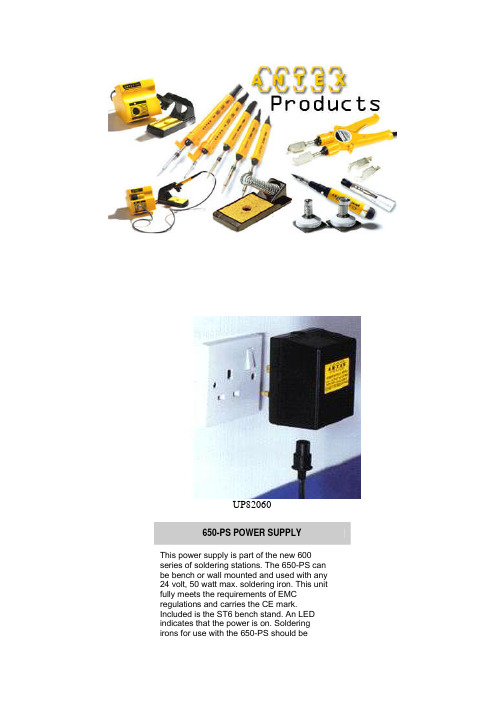
UP82060650-PS POWER SUPPLYThis power supply is part of the new 600 series of soldering stations. The 650-PS can be bench or wall mounted and used with any 24 volt, 50 watt max. soldering iron. This unit fully meets the requirements of EMC regulations and carries the CE mark. Included is the ST6 bench stand. An LED indicates that the power is on. Soldering irons for use with the 650-PS should beordered "complete with PSU plug".ENERGY REGULATOR Standard soldering irons normally operate with a tip temperature in the range 370 to 420° C (according to model and bit profile).However, there is growing use of soldering irons as hot tools in non-soldering applications requiring lower temperatures, e.g. wax painting, dental moulding, plastics etching, document preservation. The Energy Regulator permits a standard soldering iron (up to 200 watts) to be used for these applications or indeed for soldering applications where lower temperatures are required for component safety. According to model of iron, the Energy Regulator will control down to approximately 100°C..The ANTEX Energy Regulator is designed for use with any 230 volt ANTEX soldering irons with a maximum of 200 watts.The soldering iron is connected to the Energy Regulator in place of a normal mains plug.PLUG-IN POWER SUPPLY UNITThe Plug-in power supply unit offers a low cost solution for providing 24 volts for soldering.Plugging directly into a standard mains socket, the unit frees up valuable bench space. Furthermore, trailing leads from plug to transformer are eradicated. The output to the soldering iron is on the underside of the unit avoiding the likelihood of ingress of foreign matter.The unit has a maximum power rating of 25 watts making it suitable for use with the 24 volt versions of ANTEX C, M, CS, or XS irons.The unit is fitted with a male 3 pin Bulgin Socket. When ordering an ANTEX 24 volt soldering iron, always specify "with PSU plug". Alternatively plugs are available through leading component distributors.Any competitive 24 volt iron with maximum power rating of 25 watts can also be used.。
API650标准讲解

总则
焊接和补强
管壁开孔
• 管壁开孔分类:人孔 、常规法兰接口、螺纹 式管壁接管、齐平型清扫口、齐平型管壁连 接件
罐壁人孔
人孔法兰和法兰盖厚度
人孔筒节厚度和补强圈厚度
常规罐壁法兰管口和螺纹管口
常规罐壁法兰管口和螺纹管口
管子壁厚、开孔尺寸、补强板和焊接角尺寸
普通法兰管口的法兰尺寸
齐平型清扫口
罐底结构
环形罐底板-径向宽度
环形罐底板-厚度确定
本节课内容
• • • • • • • • • • • 5.7 储罐开孔 5.8 管壁连接件和罐的附件 5.9 顶部和中部抗风圈 5.10 罐顶(略) 5.11 储罐上的风载荷(倾覆稳定性计算 ) 5.12 储罐的锚固 6 制造 7 安装 8 探伤 9 焊接工艺和焊工资质认证(略) 10 标记
齐平型清扫口
齐平型连பைடு நூலகம்件
罐顶排放孔
热应力消除
API650标准讲解
韩艳娟
AP650-3013ADD2014 的组成
材料
冲击试验
设计-焊接接头
设计-大脚缝
设计-大脚缝
设计载荷
罐体容积
基础
焊缝硬度
罐壁设计-许用应力
罐壁设计方法 -一英尺法
罐壁设计方法-变点法
罐壁设计方法-弹性分析法
罐壁设计-最小壁厚
罐底板
API-650-3
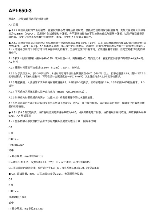
API-650-3附录A —⼩型储罐可选择的设计依据A.1 范围● A.1.1 本附录是针对⼯地组装的、容量相对较⼩的储罐所做的规定,包括买⽅规定的腐蚀裕量在内,受压元件的最⼤公称厚度为12.5mm (1/2in.)。
受压元件包括罐壁和补强板、齐平型清扫孔和齐平型接管的罐底与罐壁补强板,以及焊接到罐壁的罐底板。
但受压元件不包括其它的罐底板、盖板、接管和⼈孔接管及其法兰。
● A.1.2 本附录仅当买⽅规定时⽅可应⽤且限于设计的⾦属温度在-30℃(-20℉)以上[当采⽤镇静钢和细晶粒钢的材料时可以⽤到-40℃(-40℉)以上]。
A.1.3 本附录适⽤于第⼆章中的任何材料,尽管对于较⾼强度钢许⽤应⼒⾼并不能提供任何好处。
A.1.4 本附录仅规定了不同于本标准中基本规则的要求。
当没有规定不同要求时,必须遵循基本准则,但是宜考虑风载荷的倾覆作⽤。
A.1.5 按A.4设计的储罐(接头系数=0.85,液体⽐重=1.0,腐蚀裕量=0)的典型尺⼨、容量和壁板厚度均列在表A-1⾄A-4内。
A.2 材料A.2.1 罐壁材料厚度不应超过12.5mm (1/2in.),如A.1.1款所述。
A.2.2 对于受压元件,表2-3中列出的Ⅰ、Ⅱ组材料可⽤于设计⾦属温度在-30℃(-20℉)以上,但不必遵循2.2.9、图2-1和7.2.2的韧性要求。
Ⅲ和ⅢA 组材料,可⽤在设计⾦属温度在-40℃(-40℉)以上且应符合7.2.2中的冲击要求。
A.2.3 罐壁接管、⼈孔接管和法兰所⽤材料应遵循2.5、2.6和表2-3的要求,但不必遵循2.2.9、2.5.5和图2-1的韧性要求。
A.3设计A.3.1 不考虑接头系数的最⼤拉伸应⼒应为145Mpa (21,0001bf/in.2)。
A.3.2 计算应⼒时假设罐内充满⽔(⽐重=1.0)或者将要储存的⽐⽔重的液体。
A.3.3 各层环板应在其下部环向接头的中⼼线以上300mm (12in.)处计算拉伸⼒。
(安全生产)API 安全阀计算规定

安全阀计算规定中国石化集团公司上海医药工业设计院2001年10月12日1. 应用范围1.1 本规定仅适用于化工生产装置中压力大于0.2MPa的压力容器上防超压用安全阀的设置和计算,不包括压力大于100MPa的超高压系统。
适用于化工生产装置中上述范围内的压力容器和管道所用安全阀;不适用于其它行业的压力容器上用的安全阀,如各类槽车、各类气瓶、锅炉系统、非金属材料容器,以及核工业、电力工业等。
1.2计算方法引自《工艺设计手册》(Q/SPIDI 3PR04-3-1998),使用本规定时,一般情况应根据本规定进行安全阀计算,复杂工况仍按《工艺设计手册》有关章节进行计算。
1.3 本规定提供了超压原因分析,使用本规定必须详细阅读该章节。
2. 计算规定的一般说明2.1安全阀适用于清洁、无颗粒、低粘度流体,凡必须安装泄压装置而又不适合安全阀的场所,应安装爆破片或安全阀与爆破片串联使用。
2.2在工艺包设计阶段(PDP),应根据工艺装置的操作规范,按照本规定(见5.0章节),对本规定所列的每个工况进行分析,根据PDP的物流表,确定每个工况的排放量,填入安全阀数据表一。
2.3在基础设计阶段(BDP)和详细设计阶段(DDP),按照泄放量的计算书规定(见6.0章节),在安全阀数据表一的基础上,形成安全阀数据表二(数据汇总表)和安全阀数据表三。
安全阀数据表三作为条件提交有关专业。
3.0术语定义3.1 积聚(accumulation):在安全阀泄放过程中,超过容器的最大允许工作压力的压力,用压力单位或百分数表示。
最大允许积聚由应用的操作规范和火灾事故制定。
3.2 背压(back pressure):是由于泄放系统有压力而存在于安全阀出口处的压力,背压有固定的和变化的两种形式。
背压是附加背压和积聚背压之和。
3.3 附加背压(superimposed back pressure):当安全阀启动时,存在于安全阀出口的静压,它是由于其它阀排放而造成的压力,它有两种形式,固定的和变化的。
(650-A3)内悬浮外拉线抱杆计算样表
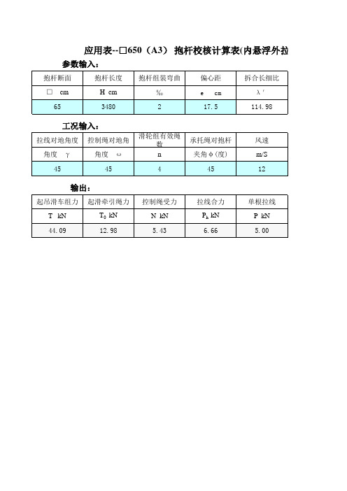
输出:
起吊滑车组力 T kN 44.09 起滑牵引绳力 T0 kN 12.98 控制绳受力 N kN 5.43 拉线合力 Ph kN 6.66 单根拉线 P kN 5.00 吊件重力 Q KN
Hale Waihona Puke 33.4悬浮外拉线分解组塔)
压应力拆减系数查取 压应力拆减系数 φ 0.464 ←按λ ′查表填入
抱杆长度(m) λ ′ φ 37.8 124.74 0.4123 34.8 114.98 0.464 31.8 105.24 0.5216 27.8 92.27 0.6061
起吊滑车组力tkn4409起滑牵引绳力t0kn1298控制绳受力nkn543拉线合力phkn666单根拉线pkn500吊件重力qkn334悬浮外拉线分解组塔压应力拆减系数查取抱杆长度m378124740412334811498046431810524052162789227060610464按查表填入动负荷系数k12抱杆倾斜角角度0起吊组偏斜角角度5承托合力kn4694吊件重力qkn334单根承托绳力kn3523整体稳定系数k稳25024882580671218729307322中间段长4030m上下段长3344m
动负荷系数 K 1.2
抱杆倾斜角 角度 δ 0
起吊组偏斜角 角度 β 5
承托合力 kN 46.94 吊件重力 Q KN
单根承托绳力 kN 35.23 整体稳定系数 K稳 2.50
33.4
24.8 82.58 0,671
21.8 72.93 0.7322
中间段长 4.0/3.0m 上下段长 3.344m
应用表--□650(A3) 抱杆校核计算表(内悬浮外拉线分解组塔)
参数输入:
抱杆断面 □ cm 65 抱杆长度 H cm 3480 抱杆组装弯曲 ‰ 2 偏心距 e cm 17.5 拆合长细比 λ ′ 114.98
Polycom SoundPoint IP 650用户手册说明书
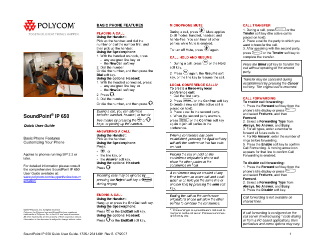
BASIC PHONE FEATURES
PLACING A CALL Using the Handset: Pick up the handset and dial the number or dial the number first, and then pick up the handset. Using the Speakerphone: 1. With the handset on-hook, press:
1
REDIAL
Press the Redial soft key or Redial to redial the most recently dialed number.Biblioteka DO NOT DISTURB
Press
to prevent the phone
from ringing on incoming calls. A Do
Call forwarding is not available on shared lines.
If call forwarding is configured on the call server (invoked using * code dialing or from a PC-based application), then particulars and menu options may vary.
CALL FORWARDING To enable call forwarding: 1. Press the Forward soft key from the phone’s idle display or press Menu and select Features, and then Forward. 2. Select a Forwarding Type from Always, No Answer, and Busy. 3. For all types, enter a number to forward all future calls to. 4. For No Answer, enter the number of rings before forwarding. 5. Press the Enable soft key to confirm Call Forwarding. A moving arrow icon appears for that line to confirm Call Forwarding is enabled.
安全阀泄放能力的计算

安全阀泄放能力的计算下面介绍的是API的安全阀计算方法,ASME的方法与API的主要不同在于ASME采用安全阀的喷嘴通过面积和安全阀的流量系数都是具体阀的实测值,而API计算采用的面积和系数都是公称数值。
1、安全阀有效通过面积1)全启式安全阀(安全阀阀芯开启高度等于或大于1/4喷嘴喉部直径)。
a——安全阀的有效通过面积,cm2;'D——安全阀喷嘴喉部直径,cm;2)微启式安全阀(安全阀阀芯开启高度小于1/4喷嘴喉部直径)。
h——阀芯开启高度,cm。
当阀座为斜面时:——斜面角度,(°)2、安全阀泄放能力的计算下面的安全阀泄放能力的计算方法在工程设计中常被采用,根据API 502推荐的计算方法进行了一些简化,使用更方便,通常情况下更保守点。
1)排放介质为气体或蒸汽时。
Q——排放量,kg/h;Ma——安全阀的有效通过面积,cm2;p——安全阀定压,Pa(G)T——排出气体的绝对温度,K;ABSM——气体相对分子质量,排出气体为混合物时,相对分子质量为平均值;rK——背压影响泄放能力的修正系数,由相关图表查得。
b2)排放介质为水蒸汽时,下面的计算公式与气体公式一样,但下式把蒸汽的物理参数计入,不需再代入。
考虑到蒸汽一般排放到大气,故一般计算时不需要考虑安全阀的背压对排放的影响;但加入了过热蒸汽修正系数,考虑蒸汽过热对泄放量的影响。
C ——过热蒸汽修正系数,查相关图表可得。
选用波纹管平衡式安全阀时,上式中的vap b K K 由代替。
3)排放介质为液体时。
a)一般液体。
1p ——定压,Pa (G );2p ——背压,Pa (G );ρ∆——液体相对密度;p K ——积聚压力修正系数,查相关图表可得b)高黏度液体。
当管内冷态为高黏度液体时,需要对排放量进行黏度修正。
一般根据流体在管道内流动得雷诺数选用黏度修正系数vis K (查相关图表可得)。
当采用波纹平衡式安全阀时,上式的右侧要乘以背压修正系数w Kc)饱和液体。