EhLib使用说明
Delphi_中DBGridEh的用法
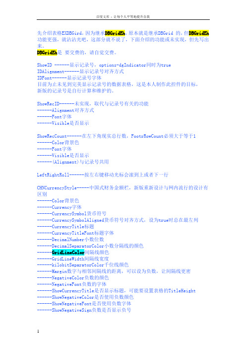
先介绍表格EXDBGird,因为继承DBGridEh,原本就是继承DBGrid 的,但DBGridEh 功能更强,就沾沾光吧,这部分就不说了,下面介绍的功能或未实现,但先写出来。
DBGridEh是要交费的,请自觉交费。
ShowID ------显示记录号,options-dgIndicator同时为trueIDAlignment------显示记录号对齐方式IDFont------显示记录号字体目前为止未见到完美显示记录号的数据表格,这是本人制作此控件的目标,新版的记录号是自行计算和维护的。
ShowRecID------未实现,取代与记录号有关的功能------Alignment对齐方式------Font字体------Visible是否显示ShowRecCount------在左下角现实总行数,FootrRowCount必须大于等于1------Color背景色------Font字体------Visible是否显示------(Alignment)与记录号共用LeftRightRoll------按左右键移动光标会滚到上或者下一行CHNCurrencyStyle-----中国式财务金额栏,新版重新设计与网内流行的设计有区别------Color背景色------Currency字体------CurrencySymbol货币符号------CurrencySymbolAligned货币符号对齐方式,设为true时总在最左列------CurrencyTitle标题------CurrencyTitleFont标题字体------DecimalNumber小数位数------DecimalSeparatorColor小数分隔线的颜色------GridLineColor间隔线颜色------GridLineWidth间隔线宽度------kilobitSeparatorColor千位线颜色------Margin数字与相邻间隔线的距离,可以设为负数,让间隔线更密------NegativeColor负数的颜色------NegativeFont负数的字体------ShowCurrencyTitle是否显示标题,可能要设置表格的TitleHeight------ShowNegativeColor是否使用负数颜色------ShowNegativeFont是否使用负数字体------ShowNegativeSign负数是否显示负号------TextLayout数字对齐方式------ZeroEmpty数据为0时是否显示要显示中国式财务金额栏,还需要在表格的Columns属性选择一个字段,将DisplayCHNCurrency设为真,把MaxWidth也设置一下,以限制宽度。
EZI-10 使用说明书
I/O 远程控制服务器EZI-10 使用者说明书Version 1.2Sollae Systems Co., Ltd.http://www.sollae.co.kr目录........................................................................................................................................................ - 1 -1产品概要........................................................................................................................................ - 3 -1.1概要......................................................................................................................................................................... - 3 -1.2构成品..................................................................................................................................................................... - 3 - 1.3产品应用构成图................................................................................................................................................ - 3 -1.4产品规格................................................................................................................................................................ - 5 -1.4.1硬件规格.......................................................................................................................................................... - 5 -1.4.2软件规格.......................................................................................................................................................... - 5 -1.4.3系统状态指示灯............................................................................................................................................. - 6 -1.4.4ISP 开关........................................................................................................................................................ - 6 -1.5接口......................................................................................................................................................................... - 7 -1.5.1输入端口.......................................................................................................................................................... - 7 -1.5.2输出端口.......................................................................................................................................................... - 7 -1.5.3以太网连接接口............................................................................................................................................ - 8 -1.5.4电源.................................................................................................................................................................. - 9 -2开始............................................................................................................................................. - 10 -2.1设定方法............................................................................................................................................................. - 10 -2.1.1通信环境检查.............................................................................................................................................. - 10 -2.1.2连接到网络.................................................................................................................................................. - 10 -2.1.3参数变更设定............................................................................................................................................. - 10 -2.2测试...................................................................................................................................................................... - 10 -2.2.1变更PC IP 地址.......................................................................................................................................... - 10 -2.2.2EZI-10 安装............................................................................................................................................... - 10 -2.2.3EZI-10 设定............................................................................................................................................... - 10 -2.2.1HTTP 测试................................................................................................................................................. - 11 -2.2.2Modbus/TCP 测试................................................................................................................................. - 12 -3设定............................................................................................................................................. - 14 -3.1IP 地址及参数值............................................................................................................................................. - 14 -3.2通过ezConfigIO的设定................................................................................................................................. - 14 -3.2.1ezConfigIO ................................................................................................................................................ - 14 -3.2.2ezConfigIO 按钮..................................................................................................................................... - 15 -3.2.3ezConfigIO ................................................................................................................................................ - 15 -3.3自动接收IP地址 (DHCP)............................................................................................................................... - 16 -3.4通过PPPoE设定IP地址................................................................................................................................... - 17 -4系统管理..................................................................................................................................... - 18 -4.1动作模式............................................................................................................................................................. - 18 -4.1.1一般模式........................................................................................................................................................ - 18 -4.1.2ISP 模式....................................................................................................................................................... - 18 -4.1.3网络诊断模式............................................................................................................................................. - 18 -4.1.4各动作模式比较....................................................................................................................................... - 18 -4.2固件升级............................................................................................................................................................. - 18 - 4.3查看当前状状态............................................................................................................................................... - 21 -4.3.1查看当前状态............................................................................................................................................. - 21 -5其他功能..................................................................................................................................... - 22 -5.1保安...................................................................................................................................................................... - 22 -5.1.1密码设定....................................................................................................................................................... - 22 -5.1.2设定允许连接的IP地址设定...................................................................................................................... - 22 -5.2初始化参数值.................................................................................................................................................... - 23 -5.2.1利用ISP按钮的参数值初始化.................................................................................................................... - 23 -6技术支援/质保期间/注意事项................................................................................................. - 24 -6.1技术支援............................................................................................................................................................. - 24 -6.2保证...................................................................................................................................................................... - 24 -6.2.1退货............................................................................................................................................................... - 24 -6.2.2无偿A/S ..................................................................................................................................................... - 24 -6.2.3有偿A/S ..................................................................................................................................................... - 24 -6.3注意事项............................................................................................................................................................. - 24 -7Revision History...................................................................................................................... - 25 -11.1概要随着互联网的不断发展,通过因特网通信的技能要求日趋增加成为趋势。
ABB AbilityTM EDCS Ekip E-Hub 产品介绍说明书
—I N FO M A R K E TI NG EL 2020-303Pasarela de conectividad Cloud para ABB Ability TM EDCS Ekip E-HubNos complace comunicar ellanzamiento de la nueva pasarela de comunicación Ekip E-Hub, que incluye la capacidad de digitalizar instalaciones nuevas o existentes e integrarlas en la solución ABB Ability TM EDCS o en sistemas digitales de terceros.FuncionalidadLa nueva pasarela Ekip E-Hub permite conectar instalaciones nuevas o existentes a la plataforma Cloud de gestión energética ABB ABility TM EDCS o a sistemas de control tipo SCADA o BMS, para optimizar sus costes operativos.Ekip E-Hub reconoce y conecta automáticamente con los dispositivos de ABB Electrification a través del puerto de conectividad Ethernet (protocolo Modbus TCP) y del puerto serie RS485 (protocoloModbus RTU). Adicionalmente, el módulo opcional de señales de entrada permite leer medidas de pulsos digitales o estados de la aparamenta (6 entradas digitales configurables) y señales analógicas (2 entradas 4…20mA y 2 entradas 0…36V).La conectividad aguas arriba, ya sea a la plataforma ABB Ablity TM o a un sistema de control tipo SCADA oBMS, se realiza mediante el puerto Ethernet.Módulos enchufables Ekip Com como alternativa Los módulos enchufables Ekip Com son unaalternativa en aquellos casos donde sea posible el uso de dispositivos como Emax 2, Tmax XT, Ekip UP o TruONE ATS. En este caso, Ekip Com Hub permite la conexión a ABB Ability TM EDCS y Ekip Com Modbus TCP (u otros módulos Ekip Com con protocolos de comunicación estándares) permite la conexión a sistemas de control tipo SCADA o BMS.Configuración y puesta en marchaLa herramienta de configuración de la nuevapasarela Ekip E-Hub es el software Ekip Connect, una herramienta gratuita de configuración, supervisión y diagnóstico para otras gamas de producto como Emax 2, Tmax XT, Ekip UP, M4M, TruONE ATS, etc.Ekip Connect reconoce automáticamente la pasarela Ekip E-Hub, conectando el PC al puerto Ethernet del dispositivo.Ekip Connect Ekip E-HubEn cuanto a dimensiones:Características técnicas Alimentación 9…36 V DCMontaje Carril DIN 35mm (DIN EN 60 715)IPIP40Temperatura de trabajo -20…+70ºCDimensiones 198,0 x 90,3 x 48,4 mm Norma IEC62368-1Antena 3G Opcional (necesarias 2uds)Memoria interna4GB eMMCConectividadPuertos y protocolos2x RJ45 Ethernet – Modbus TCP2x RS-485 - Modbus RTU 2x USB 2.02x MicroSIM – 3G (no suministrada)Módulo opcional E/S6x Entradas digitales 24 V DC 4x Entradas analógicasCaracterísticas principalesLas características técnicas principales de la nueva pasarela Ekip E-Hub son:—01Ejemplo conectividadcon los dispositivos deprotección, medida ygestión de la energía—01—(*) Únicamente se muestran los códigos incluidos en tarifa PDF 2020. Parael resto de códigos y precios consultar la tarifa electrónica o PDC.Códigos de pedido (*)Código pedido Descripción Precio unit. €GTV ABC Sum.mín./Embalaje Ud ConectividadI N F O M A R K E T I N G E L 2020-303Haga click en la imagen para acceder a la documentaciónHaga click en la imagen para acceder a la documentación—Manual técnico Ekip E-HubPresentación PDF de lanzamiento Ekip E-HubHaga click en la imagen para acceder a la webPágina web soluciones digitales de supervisión de la energíaHaga click en la imagen para acceder a la documentaciónManual usuario Ekip E-Hub Haga click en la imagen para acceder a la documentaciónFolleto ABB ABility TM EDCS—Pau MasgrauABB Ability™ Market Development ManagerAsea Brown Boveri, SA Low Voltage Products Tel.: 93 484 22 25Fax: 93 484 21 90www.abb.es/bajatension。
Ehlib使用大全
Ehlib使用大全
一、Ehlib 概述
Ehlib 是用于 Delphi 的一个组件库,它包含了大量的控件和功能,
可以帮助开发人员快速构建功能丰富的应用程序。
Ehlib 支持 Delphi 的
各个版本,包括 Delphi 5 至 Delphi XE8、Delphi 10 Seattle、Delphi
10.1 Berlin 和 Delphi 10.2 Tokyo。
二、Ehlib 的主要功能
1.数据库控件
2.数据集控制
3.表格控件
5.图表控件
Ehlib 提供了多种图表控件,包括 TDBChartEh、TDBVertLineSeries、TDBHorizLineSeries等。
开发人员可以利用这些控件绘制各种类型的图表,如柱状图、折线图、饼图等。
6.数据导入导出
7.打印和报表功能
8.布局管理
三、Ehlib 的使用方法
2. 添加 Ehlib 到 Delphi 工程
3. 使用 Ehlib 的控件和功能
4.编写代码
可以通过编写代码来进一步配置和操作 Ehlib 的控件和功能。
可以使用 Ehlib 提供的 API 来实现各种操作,如数据的增删改查、控件的事件处理等。
四、总结
Ehlib 是一个功能丰富的 Delphi 组件库,提供了各种各样的控件和功能,可以帮助开发人员更高效地开发应用程序。
本文介绍了 Ehlib 的概述、主要功能和使用方法,希望能对开发人员在使用 Ehlib 进行应用程序开发时有所帮助。
DELPHI 表格控件DBGridEh全属性设置详解 最全的属性设置说明

DELPHI 表格控件DBGridEh属性设置详解----白波九道-----Allowedoperations[alopInsertEh,alopUpdateE h,alopDeleteEh,alopAppen dEh]允许操作类型:插入、更新、删除、追加Allowedselections[gstRecordBookmarks,gst Rectangle,gstColumns,gst All] gstRecordBookmarks:书签选中行 gstRectangle :区域选择 gstColumns :列选择 gstAll :所有AutoFitColWidths以自动重置列宽来设置网格的宽度等于客户区宽度AlwaysShowEditBu tton列显示下拉编辑按钮 AutoDropDown 自动下拉框DblClickNextVal 双击单元格为下一个值,数值为加1,列表下下一个 DropDownShowTitl es下拉框显示标题 DropDownSizing 下拉框可否手动调整大小 EndEllipsis 列内容显示不全的显示省略号 [Footer].Tooltips 底栏是否显示提示 HighLightRequired Layout内容位置 Alignment 标题对齐方式 Color 标题颜色EndEllipsis 标题过长用省略号结束 Orientation 标题文字方向 TitleButton 是否显示标题按钮 TitleTooltips 标题是否显示提示 ColumnDefValuesEh (列缺省值)Tooltips是否显示提示Columns[index]/Columns[ColumnName] 列对象,可用索引和名称调用 ColumnsOptimizeWidth根据内容自动调整列宽 Constraints 控件尺寸约束规定 ContraColCount 右侧锁定列 Ctl3D 3d 风格显示 Cursor显示鼠标指针样式 Active 激活数据分组 Color汇总行颜色DefaultStateExpand ed 默认显示是否为为全展开 Font 汇总行字体显示选项DataGrouping(数据分组设置) 表格中显示如EXCEL 中的分类汇总效果须加 MemT ableEh DataSetDriverEh,GroupLevels分组的级数如先按国别分组再按城市分GroupPanelVisible是否显示顶部的分组图示面板 ParentColor 使用父件颜色设置 Uses 添加EhLibMTE ParentFont 使用父件字体设置 AutoEdit自动提交表格修改到数据源 Dataset 数据集选项 Enabled 启用数据源 Datasoure (数据源设置) Tag 数据源标记(LongInt)DefaultDrawing 使用缺省的方式绘制表格,如为FALSE 须 OnDrawDataCell 事件中提供自己的例程 DrawGraphicDataDrawMemoText显示文本式备注字段EditActions[geaCutEh,geaCopyEh,gea PasteEh,geaDeleteEh,geaS electAllEh] 编辑属性,设置是否可以剪切、复制、粘贴、删除、选择 sebshowOnlyforCur Celleh只在当前单元格显示 sebshowOnlyforCur Roweh只在当前行显示 sebshowOnlyWhen GridActiveEh 当表格激活时显示EditButtonShowOptio ns(编辑按钮显示选项)sebshowOnlyWhen DataEditingEh当单元格进入编辑状态时显示 EvenRowColor 偶数行颜色FixedColor 固定区域颜色(如表头列头) Flat 平面显示效果(标题行渐变色须启用) Font 字体设置选项 FooterColor 底栏颜色 FooterFont 底栏字体设置 FooterRowCount 底栏行数 FrozenCols左侧冻结列数 ExtScrollBarSmoothStep True 平滑滚动/False 按列滚动 Tracking True 跟踪显示/Fasle 松开后显示 HorzScrollBar (水平滚动条设置) Visible 是否显示 Imemode 输入法模式选项 ImeName输入法 gioShowRowIndicatorEh 显示行指针 gioShowRecNoEh 显示行号 IndicatorOption (行首指示选项)gioShowRowselCheckbox esEh显示行选择框 IndicatorTitle (行道指示标题)DropdownMenupmNoVisibleCols/ PopupMenu1表头下拉菜单样式ShowDropdownSign显示下拉箭头图案 TitleButton 按钮是否启用 UseGlobalMenu用全局菜单 Left左端位置 MinAutoFitWidth 自适应宽度最小值 Name 控件名称 OddRowColor奇数行颜色 dgEdit能否编辑,dgAlwaysShowEditor 总是显示编辑项,选中时单击单元格直接进入编辑状态,否则双击进入编辑状态 dgTitles 显示列标题 dgIndicator 显示行首指针dgColumnResize 可否调整列宽 dgColLines 显示列线 dgRowLines 显示行线dgTabs 接收TAB 键移动到下一单元格 dgRowSelect整行选择 dgAlwaysShowSelection 显示选择区域 dgConfirmDelete 删除时确认 dgCancelOnExitOptions(表格通用选项)dgMultiSelect 可多行选择dghFixed3D 固定区(表头列头)3D 效果(渐变色须启用) dghFrozen3D 冷区3D 效果 dghFooter3D 栏底3D 效果 dghData3D数据区3D 效果 dghResizeWholeRightPartdghHighlightFocus 高光选择焦点dghClearSelection 移到下一个单元时是否清除已选记录 dghFitRowHeightToText 按文本适应行高 dghAutoSortMarking 自动排序 dghMultiSortMarking 多级排序 dghEnterAsTab 回车键作为TAB dghTraceColSizing 移动列宽时动态显示内容dghIncSearch允许在数据网格中进行增量搜索 Ctrl+F - 开始增量搜索。
E2020HB 显示器简化服务手册说明书
Simplified Service Manual–E2020HBVersion: 01Date:2021/03/04Content Index1. General Safety Instructions (3)1.1 SAFETY: General Safety (3)1.2 SAFETY: General Power Safety (5)2. Exploded view diagram with list of items (6)3. Wiring connectivity diagram (7)4. Disassembly and Assembly Procedures (8)4.1 Disassembly SOP (8)4.2 Assembly SOP (12)5. Trouble shooting instructions (15)1. General Safety InstructionsUse the following safety guidelines to help ensure your own personal safety and to help protect your equipment and working environment from potential damage.NOTE: In this section, equipment refers to monitors.IMPORTANT NOTICE FOR USE IN HEALTHCARE ENVIRONMENTS:Dell products are not medical devices and are not listed under UL or IEC 60601 (or equivalent). As a result, they must not be used within 6 feet of a patient or in a manner that directly or indirectly contacts a patient1.1 SAFETY: General SafetyWARNING: To prevent the spread of fire, keep candles or other open flames away from this product at all times.When setting up the equipment for use:⏹Place the equipment on a hard, level surface. Leave 10.2 cm (4 in) minimum of clearance onall vented sides of the computer to permit the airflow required for proper ventilation.⏹Restricting airflow can damage the computer or cause a fire.⏹Do not stack equipment or place equipment so close together that it is subject torecalculated or preheated air.⏹NOTE: Review the weight limits referenced in your computer documentation before placinga monitor or other devices on top of your computer.⏹Ensure that nothing rests on your equipment's cables and that the cables are not locatedwhere they can be stepped on or tripped over.⏹Ensure that all cables are connected to the appropriate connectors. Some connectors havea similar appearance and may be easily confused (for example, do not plug a telephonecable into the network connector).⏹Do not place your equipment in a closed-in wall unit or on a bed, sofa, or rug.⏹Keep your device away from radiators and heat sources.⏹Keep your equipment away from extremely hot or cold temperatures to ensure that it is usedwithin the specified operating range.⏹Do not push any objects into the air vents or openings of your equipment. Doing so cancause fire or electric shock by shorting out interior components.⏹Avoid placing loose papers underneath your device. Do not place your device in a closed-inwall unit, or on a soft, fabric surface such as a bed, sofa, carpet, or a rug.When operating your equipment:⏹Do not use your equipment in a wet environment, for example, near a bath tub, sink, orswimming pool or in a wet basement.⏹Do not use AC powered equipment during an electrical storm. Battery powered devices maybe used if all cables have been disconnected.⏹Do not spill food or liquids on your equipment.⏹Before you clean your equipment, disconnect it from the electrical outlet. Clean your devicewith a soft cloth dampened with water. Do not use liquids or aerosol cleaners, which maycontain flammable substances.⏹Clean the monitor display with a soft, clean cloth and water. Apply the water to the cloth,then stroke the cloth across the display in one direction, moving from the top of the displayto the bottom. Remove moisture from the display quickly and keep the display dry.⏹Long-term exposure to moisture can damage the display. Do not use a commercial windowcleaner to clean your display.⏹If your equipment does not operate normally - in particular, if there are any unusual soundsor smells coming from it - unplug it immediately and contact an authorized dealer or servicecenter.Protecting Against Electrostatic DischargeElectrostatic discharge (ESD) events can harm electronic components inside your equipment. Under certain conditions, ESD may build up on your body or an object, such as a peripheral, and then discharge into another object, such as your computer. To prevent ESD damage, you should discharge static electricity from your body before you interact with any of your equipment’s internal electronic components, such as a memory module. You can protect against ESD by touching a metal grounded object (such as an unpainted metal surface on your computer’s I/O panel) before you interact with anything electronic. When connecting a peripheral (including handheld digital assistants) to your equipment, you should always ground both yourself and the peripheral before connecting it. In addition, as you work inside the equipment, periodically discharge any static charge your body may have accumulated.You can also take the following steps to prevent damage from electrostatic discharge:⏹When unpacking a static-sensitive component from its shipping carton, do not remove thecomponent from the antistatic packing material until you are ready to install the component.Just before un wrapping the antistatic package, be sure to discharge static electricity fromyour body.⏹When transporting a sensitive component, first place it in an antistatic container orpackaging.⏹Handle all electrostatic sensitive components in a static-safe area. If possible, use antistaticfloor pads and work bench pads.1.2 SAFETY: General Power SafetyObserve the following guidelines when connecting your equipment to a power source:⏹Check the voltage rating before you connect the equipment to an electrical outlet to ensurethat the required voltage and frequency match the available power source.⏹Do not plug the equipment power cables into an electrical outlet if the power cable isdamaged⏹Norway and Sweden: If this product is provided with a 3-prong power cable, connect thepower cable to a grounded electrical outlet only.⏹If you use an extension power cable, ensure that the total ampere rating of the productsplugged in to the extension power cable does not exceed the ampere rating of the extension cable.⏹If you must use an extension cable or power strip, ensure the extension cable or power stripis connected to a wall power outlet and not to another extension cable or power strip. Theextension cable or power strip must be designed for grounded plugs and plugged into agrounded wall outlet.⏹If you are using a multiple-outlet power strip, use caution when plugging the power cable intothe power strip. Some power strips may allow you to insert a plug incorrectly. Incorrectinsertion of the power plug could result in permanent damage to your equipment, as well asrisk of electric shock and/or fire. Ensure that the ground prong of the power plug is insertedinto the mating ground contact of the power strip.⏹Be sure to grasp the plug, not the cable, when disconnecting equipment from an electricsocket.If your equipment uses an AC adapter:⏹Use only the Dell provided AC adapter approved for use with this device. Use of another ACadapter may cause a fire or explosion.⏹NOTE: Refer to your system rating label for information on the proper adapter modelapproved for use with your device.⏹Place the AC adapter in a ventilated area, such as a desk top or on the floor, when you useit to run the computer or to charge the battery. Do not cover the AC adapter with papers orother items that will reduce cooling; also, do not use the AC adapter inside a carrying case.⏹The AC adapter may become hot during normal operation of your computer. Use care whenhandling the adapter during or immediately after operation.⏹It is recommended that you lay the adapter on the floor or desk so that the green light isvisible. This will alert you if the adapter should accidentally go off due to external effects. Iffor any reason the green light goes off, disconnect the AC power cord from the wall for aperiod of ten seconds, and then reconnect the power cord.⏹Japan Only: Use only the Dell-provided AC power cable with the AC adapter. Use of anyother power cable may damage the device or AC adapter or may present risk of fire orelectric shock.2. Exploded view diagram with list of itemsItem no DescriptionQ'TY 1 ASSY BZL1 2 PCBA CTRL BD1 3 SCRW TP-B FPH M2*2.4L ZN 3 4 Panel1 5 MYLAR PWR1 6 SCRW PH INT/TOO M3*9TP-S C-ZN 5 7 PCBA I/F BD 1 8 PCBA SPS BD 1 9 ASSY SHD MAIN 1 10 ASSY RC1 11 SCRW FPHM4*10L(7.7/1.6)B-ZNNY 4 12 ASSY CVR VESA 1 13 ASSY CLMN 1 14 ASSY BASE 1 15 Power cable 1 16 VGA cable 1 17DP cable115 16173. Wiring connectivity diagramWire 1FFC 14. Disassembly and Assembly Procedures4.1 Disassembly SOPPreparation before disassembly 1. Clean the room for disassembly 2. Identify the area for monitor3. Prepare the equipment, tool and material as bellow: 1) Working table2) Philips-head screwdriver 3) Hex-head screwdriver 4) Glove5) Cleaning cloth 6) ESD protectionItem PictureOperationToolNotes 11. Place the monitor on a soft cloth along the desk.2. Remove VESAcover to access the release button.21. Use a long and thinscrewdriver to push the release latch located in a hole just above the stand.2. Once the latch isreleased, remove the base away from the monitor.Philips-head screwdriver23. Press down on thequick release tab latch on the bottom of the base toseparate base from stand column.31. Unlock 4 screws onRear CoverPhilips-head screwdriverTorsion of screw: 8~10Kg41. Disassemble RearCover from the monitor2. Notice thedisassembly order: 1) Disassemble the Top part2) Disassemble the Left / Right part 3) Disassemble the Bottom part4) Remove RC from Bezel1234231251. Remove Control BD FFC cable from I/F BD2. Remove backlightwire from SPS BD61. Remove LVDS cable from panel2. Take off Main SHDfrom Panel71. Disassemble Safety Mylar from Main SHD81. Unlock 5 PCBAscrews and 2 hex screws2. Disassemble SPSBD and I/F BD from Main SHD3. Remove SPS wirefrom I/F BD4. Remove LVDScable from I/F BD1. Philips-headscrewdriverTorsion of PCB screw: 6.5±1.0Kg2. Hex-head screwdriverTorsion of hex screw: 5.0±0.6Kg124.2 Assembly SOPPreparation before assembly1. Clean the room for disassembly2. Identify the area for monitor3. Prepare the equipment, tool and material as bellow: 1) working table2) Philips-head screwdriver 3) Hex-head screwdriver 4) Glove5) Cleaning cloth 6) ESD protectionItemPicture OperationTools Notes 11. Assemble SPS BD in mainSHD2. Insert LVDS cable into I/F BD.3. Insert the wire into I/F BD andassemble I/F BD into Main SHD4. Lock 5 PCB screws and 2 hexscrews1. Philips-head screwdriverTorsion of PCB screw: 6.5±1.0Kg2. Hex-head screwdriverTorsion of hex screw: 5.0±0.6Kg21. Assemble Safety Mylar onMain SHD31. Place Panel on a soft cloth or cushion2. Place Main SHD on panel andInsert LVDS cable into panel41. Insert backlight wire into SPS BD2. Insert Control BD FFC cableto I/F BD and paste Control BD FFC cable on Main SHD and Panel51. Assemble Rear Cover withBezel2. Follow the sequence to presson Rear Cover to make it be assembled with Bezel tightly61. Lock 4 screws on Rear Cover Philips-headscrewdriverTorsion of screw: 8.5±1.0Kg445123 45221371. Assemble the stand column to stand base.81. Attach the stand assembly tothe monitor.2. Attach the VESA Cover onRear Cover5. Trouble shooting instructions。
delphi第三方控件安装方法

安装方法:
就目前常见的各种形式的组件的安装方法介绍一下。
1 只有一个DCU文件的组件。DCU文件是编译好的单元文件,这样的组件是作者不想把源码公布。一般来说,作者必须说明此组件适合Delphi的哪种版本,如果版本不对,在安装时就会出现错误。也正是因为没有源码,给使用者带来了不便,那就是一旦Delphi版本升级,此组件就不能再使用了,当然有的作者给出了几种版本的DCU文件,用户根据需要选择使用。这样的组件的安装方法是:在Component菜单中,选择install component,在对话框
5、ActiveX控件的安装。要安装这类控件,需要先用regsvr32.exe注册,然后选择Component菜单中Import ActiveX Control项。在Import ActiveX Control打开的窗口中,只有已经注册的ActiveX控件才出现在列表中,选中一个然后按Install按钮就可以安装了。如果事先没有用regsvr32.exe注册也可以按ADD按钮找到OCX文件即时注册,注册后再进行安装。
红帽Ansible自动化工具产品介绍说明书

/redhatinc@redhat /company/red-hat“Our automatedprocesses are enabled in Ansible Tower. Now,even individuals whodon’t have knowledgeabout a differentoperating system ornetwork device areenabled to manageand fix things that arecompletely outsideof their comfort zone.They don’t have toenter things manuallyor follow a guide. It’salready written andautomated for them.”1Lead architectManaged service providerProduct overview Red Hat® Ansible® Automation, is a powerful tool for the orchestration of enterprise environments. Ansible Automation manages the Ansible technology used by thousands of organizations globally to help them automate IT tasks such as configuration management, provisioning, workflow orchestra-tion, application deployment, and life-cycle management. One of Ansible’s hallmarks is its low barrier to entry. Ansible is agentless, meaning that no changes to your servers or network equipment are necessary to start using it. It is simple enough that you can install it and get started within minutes. When you are ready, Red Hat Ansible Tower adds to the sim-plicity of Ansible with improved security, scale, and scope. Ansible allows you to use workflows to streamline jobs, and it provides simple tools for sharing solu-tions with your team. You can centralize and control your IT infrastructure with a visual dashboard, role-based access control (RBAC), job scheduling, integrated notifications, and graphical inventory management. Additionally, it is easy to embed Ansible Tower into existing tools and processes via its RESTful application programming interface (API). Scale with confidence Red Hat Ansible Tower features automation, scheduling, and clustering that helps organizations scale more securely without adding staff or expensive appliances. • Manage multiple environments. Simultaneously manage multiple geographically (or other-wise) diverse environments from the Ansible Tower dashboard. One person can manage multiple systems or deploy applications to various environments. • Maintain security and permissions. Red Hat Ansible Tower’s RBAC creates necessary separa-tion and isolation of users and resources. The operations team and a team of developers working on a subset of services can both safely use Ansible Tower to work only on the systems in the environ-ments to which they have access. • Empower teams. Red Hat Ansible Tower gives disparate teams a centralized environment for automation. Groups can share the playbooks and workflows among numerous teams, all while maintaining a clear separation as they share institutional knowledge about application deployments and infrastructure management across an organization. Ansible Tower scales operations to meet the needs of administrators, developers, network engineers, and other IT teams, as well as line of business teams.1Forrester, “The Total Economic Impact of Red Hat Ansible Tower.” June 2018.DatasheetRed Hat Ansible Automation Scale IT automation, manage complex deployments, and speed productivityOrchestration of enterprise environmentsIt is rare that one vendor can keep up with an organization’s needs, let alone provide all the best infra-structure and systems. Red Hat Ansible Tower is a single tool to manage multivendor environments, multicloud, hybrid clouds, and more. It can orchestrate the following:• Operating systems: Red Hat Enterprise Linux®, Windows, Ubuntu, and more.• Servers: HP, Dell, Cisco, and more.• Cloud: Amazon Web Services, Microsoft Azure, Google Cloud Platform, DigitalOcean, CloudStack, OpenStack®, Rackspace, Packet, and more.• Infrastructure: Red Hat OpenShift®, VMware, NetApp, Kubernetes, Jenkins, JBoss®, Docker,and more.• Networks: Arista, Cisco, Juniper, F5, Palo Alto, and more.Application management and deployment is a complex process that can have enormous impact on day-to-day operations. Red Hat Ansible Automation can help with management of the entire life cycle, including the following:• C ode deployments.• B uild automation.• A rtifact management.• C ertificate management.• S ervice restarts.• D ecommissioning resources.Using a workflow that can touch multiple facets of environments and beyond can enable unfamiliar staff to safely make changes without involving engineers from various disciplines. Red Hat Ansible Tower connects the tools and processes each team prefers to use into a coherent, orchestrated process with security.Window into your infrastructureEmpowering staff to consume resources on demand speeds development and significantly lightens the load on infrastructure and operations. With Red Hat Ansible Automation, you can build a custom-ized set of self-service capabilities to enable developers to self-fulfill authorized responsibilities. Ansible Automation gives you the ability to codify your organizational processes and convert them into automated and governed workflows, helping you better manage your resources. It allows resources to be tagged in a manner that can identify when and how they were created—and by whom—and what runs on or has been deployed to those resources.With Red Hat Ansible Tower, you can:• Optimize costs. Templating common resources used within an organization to optimize utilization of on-premise resources or public cloud providers allows organizations to put workloads and data where they are most cost-effective. Spinning down at night the resources that are marked Dev or decommissioning resources tagged as proof of concept can drastically reduce the sprawl of enter-prise environments.• Divide responsibilities. RBAC allows the right people to have the right level of access to the right resources. Red Hat Ansible Tower lets organizations easily control who can run what tasks on what inventories. Sarbanes-Oxley Act (SOX) compliance and General Data Protection Regulation (GDPR) compliance are easier with Ansible Tower.• Audit. Use Red Hat Ansible Tower as a centralized point to manage and orchestrate environments. Activity streams on every page in Ansible Tower show who did what—and when. Activity can also be forwarded to log aggregators, security tools, and other endpoints.• Maintain security. Use Red Hat Ansible Automation to create standard, reusable configura-tions that meet your organization’s security and access needs. Ansible Tower allows staff to create secured infrastructure that complies with various regulatory, compliance, or authorization frame-works (PCI, DSS, NIST, CIS, FISMA, HIPAA).DevOps visualizedCreating a stable, safe, and well-functioning software delivery pipeline is an important component of the software development life cycle. Being able to provide transparency into that pipeline is impera-tive to building trust in it. Red Hat Ansible Tower fulfills many of the roles historically performedby operations, helping developers gain access to the capabilities they require. Ansible Tower is the window into software delivery to ensure that development and operations are running safely in your organization.• Everything in a pipeline. There are many benefits of gluing together all the tooling into a soft-ware delivery pipeline orchestrated by Red Hat Ansible Tower. Code can safely and reliably move from check-in, to testing, to security scanning, through environments, and off to production.• Continuous improvement. Organizations that iteratively improve upon and add capabilities to their stacks can continuously learn from their infrastructure and systems. When the entire software delivery pipeline is presented to you in Red Hat Ansible Tower, you can more accurately measure what is providing value—and what is not. Metrics matter, and Ansible Tower can illuminate multiple facets of an IT organization.• Single command, playbooks, workflows. Some problems are fixed by a single command, and others are fixed by a series of steps. Software deployments are a series of processes. Red Hat Ansible Automation can cover all those tasks across entire organizations.• Want to run one command on every Windows Server 2016 system? Ansible Tower enables that through an intuitive user interface (UI).• Want to run commands to mitigate a zero-day vulnerability across all systems? AnsibleAutomation can do that simultaneously on multiple operating systems across the globe.• Need a group of systems to be updated as part of a release? An Ansible Tower workflow tracks a full set of independent jobs as a single unit.The business value of an Ansible Tower subscriptionRed Hat’s approach to software goes against the traditional licensing model and vendor lock-in, giving you freedom and choice for your organization’s needs. With a Red Hat subscription, you get the latest technology with the assurance you need to keep your organization up and running. You also benefit from the expertise of engineers making software the open source way.Customers should contact Red Hat—but not just when a problem arises. Whether you are planning, testing, deploying, maintaining, or upgrading your infrastructure, when you engage with Red Hat Support, you are often working with the people who write and test the software. It is a truly collabora-tive and consultative relationship.Open source software has shown that the world can benefit from groups of people solving problems collaboratively. The collective knowledge-sharing power of a Red Hat Ansible Automation subscrip-tion helps your organization move faster and safer, allowing it to benefit from decades of lessons learned. A subscription also provides tailored solutions unique to the needs of your organization./redhatinc@redhat /company/red-hat North America1 888 REDHAT1About Red HatR ed Hat is the world’s leading provider of enterprise open source software solutions, using a community-powered approach to deliver reliable and high-performing Linux, hybrid cloud, container, and Kubernetes technologies. Red Hat helps customers integrate new and existing IT applications, develop cloud-native applications, standardize on our industry-leading operating system, and automate, secure, and manage complex environments. Award-winning support, training, and consulting services make Red Hat a trusted adviser to the Fortune 500. As a strategic partner to cloud providers, system integrators, application vendors, customers, and open source communities, Red Hat can help organizations prepare for the digital future.Europe, Middle East,and Africa00800 7334 2835*****************Asia Pacific+65 6490 4200***************Latin America+54 11 4329 7300********************* Real-world resultsThousands of customers around the world use Red Hat Ansible Automation to automate IT tasks across servers, clouds, networks, and more. A 2018 study by research firm Forrester found the follow-ing results for Red Hat Ansible Tower:2• Return on investment of 146% over 3 years.• Payback in less than 3 months.Visit /resources for more information on Red Hat Ansible Automation and to watch customer success story videos.2 Forrester, “The Total Economic Impact of Red Hat Ansible Tower.” June 2018.Datasheet。
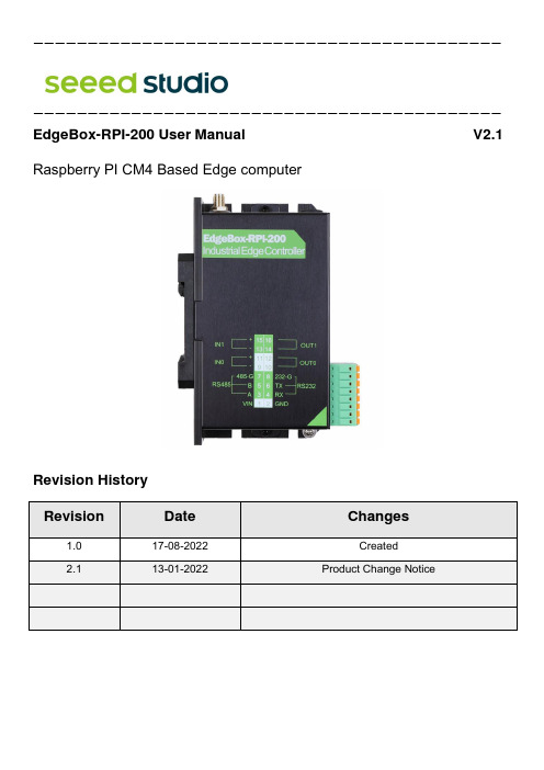
EdgeBox-RPI-200 基于Raspberry PI CM4的边缘计算机用户手册说明书
——————————————————————————————————————————————————————————————————————————————————————EdgeBox-RPI-200 User Manual V2.1Raspberry PI CM4 Based Edge computerRevision HistoryRevision Date Changes1.0 17-08-2022 Created2.1 13-01-2022 Product Change NoticeProduct Change Notice:As a part of our continual improvement process, we made the below changes in hardware version D.There is impact on the software due to this change.CP2104->CH9102FUSB2514B->CH334UCP2105->CH342FThe description in the Linux have been changed:ttyUSB0-> ttyACM0ttyUSB1-> ttyACM1MCP79410->PCF8563ARZThe address of the new RTC is 0x51.Contents1 Introduction (1)1.1 Features (1)1.2 Interfaces (2)1.2.1 Multi-Func phoenix connector (3)1.3 Block Diagram (4)2 Installation (5)2.1 Mounting (5)2.2 Connectors and Interfaces (6)2.2.1 Power supply (6)2.2.2 Serial Port (RS232 and RS485) (7)2.2.3 DI&DO (8)2.2.4 HDMI (9)2.2.5 Ethernet (9)2.2.6 USB HOST (9)2.2.7 Console (USB type-C) (9)2.2.8 LED (10)2.2.9 SMA Connector (11)2.2.10 NANO SIM card slot (Optional) (11)2.2.11 Mini-PCIe (12)2.2.12 M.2 (14)3 Drivers and Programming Interfaces (15)3.1 LED (15)3.2 Serial Port (RS232 and RS485) (15)3.3 Cellular over Mini-PCIe (Optional) (15)3.4 WDT (19)3.4.1 Block Diagram of WDT (19)3.4.2 How it works (19)3.5 RTC (21)3.5.1 RTC Chip information (21)EdgeBox-RPI-200 User Manual3.6 UPS for safe shut down (Optional) (23)4 Electrical specifications (24)4.1 Power consumption (24)4.2 UPS (Optional) (24)5 Mechanical Drawings (24)1 IntroductionEdgeBox-RPI-200 is a rugged fan less Edge Computing Controller with Raspberry Pi Computer Module 4(CM4) for harsh industry environment. It can be used to connect the field networks with cloud or IoT applications. It is designed from the ground up to meet the challenges of rugged applications at competitive prices, ideal for small business or small order with scale multi-level demands.1.1 Features•State-of-the-art Aluminum chassis for Harsh environment•Integrated passive heat sink•Built-in mini PCIe socket for RF module, such as 4G, WI-FI, Lora or Zigbee•SMA antenna holes x2•Encryption chip ATECC608A•Hardware Watchdog•RTC with Super Capacitor•Isolated DI&DO terminal•35mm DIN Rail support•Wide power supply from 9 to 36V DC•Optional: UPS with SuperCap for safe shutdown*•Raspberry Pi CM4 onboard WiFi 2.4 GHz, 5.0 GHz IEEE 802.11 b/g/n/ac equipped**•Raspberry Pi CM4 onboard Bluetooth 5.0, BLE equipped**These features make the EdgeBox-RPI-200 designed for easy setup and quick deployment for typical industrial applications, such as status monitoring, facility management, digital signage and remote control of public utilities. Furthermore, it is a user-friendly gateway solution with 4 cores ARM Cortex A72 and most industry protocols can save on total deployment costs including electrical power cabling cost and help reduce the product’s deployment time. Its ultra-lightweight and compact design is the answer for applications in space-constricting environments ensures it can operate reliably in a variety of extreme environments including in-vehicle applications.NOTE: For UPS function please contact us for more information.: WiFi and BLE features can be found in 2GB and 4GB versions.1.2 Interfaces① Multi-Func phoenix connector② Ethernet connector③ USB 2.0 x 2④HDMI⑤LED2⑥LED1⑦ SMA antenna 1⑧ Console (USB type C)⑨ SIM card slot⑩ SMA antenna 21.2.1 Multi-Func phoenix connectorNote Func name PIN # PIN# Func name Note POWER 1 2 GNDRS485_A 3 4 RS232_RXRS485_B 5 6 RS232_TXRS485_GND 7 8 RS232_GNDDI0- 9 10 DO0_0DI0+ 11 12 DO0_1DI1- 13 14 DO1_0DI1+ 15 16 DO1_1NOTE: 24awg to 16awg cable are suggested1.3 Block DiagramThe processing core of the EdgeBox-RPI-200 is a Raspberry CM4 board. A specific base board implements the specific features. Refer to next figure for the block diagram.2 Installation2.1 MountingThe EdgeBox-RPI-200 is intended for two wall mounts, as well one with 35mm DIN-rail. Refer to next figure for the recommended mounting orientation.2.2 Connectors and Interfaces2.2.1 Power supplyPin# Signal Description1 POWER_IN DC 9-36V2 GND Ground (Reference potential)The PE signal is optional. If there is no EMI present, the PE connection can leave open.2.2.2 Serial Port (RS232 and RS485)Pin# Signal Description4 RS232_RX RS232 receive line6 RS232_TX RS232 transmit line8 GND Ground (Reference potential)Pin# Signal Description3 RS485_A RS485 difference line high5 RS485_B RS485 difference line low7 RS485 _GND RS485 Ground (isolated from GND)The RS485_GND signal is isolated with “GND” signal. If a shielded twisted pair wire is used, the RS485 _GND is connected to the shield.NOTE: The 120 Ohm termination resistor for RS485 has been installed inside.2.2.3 DI&DOPin# Signal ofterminal PIN Levelof activePIN of GPIO fromBCM2711NOTE09 DI0-HIGH GPIO1711 DI0+13 DI1-HIGH GPIO2715 DI1+10 DO0_0HIGH GPIO2312 DO0_114 DO1_0HIGH GPIO2416 DO1_1NOTE:NOTE:1. DC voltage for input is 24V (+- 10%).2. DC voltage for output should be under 60V, the current capacity is 500ma.3. Channel 0 and channel 1 of input are isolated to each other4. Channel 0 and channel 1 of output are isolated to each other2.2.4 HDMIDirectly connected to the Raspberry PI CM4 board with TVS array.2.2.5 EthernetEthernet interface is same as Raspberry PI CM4,10/100/1000-BaseT supported, available through the shielded modular jack. Twisted pair cable or shielded twisted pair cable can be used to connect to this port.2.2.6 USB HOSTThere are two USB interfaces at the connector panel. The two ports share the same electronic fuse.NOTE: Max current for both ports is limited to 1000ma.2.2.7 Console (USB type-C)The design of console used a USB-UART converter, most OS of the computer have the driver, if not, the link below may be useful:This port is used as a Linux console default. You can log into the OS use the settings of 115200,8n1(Bits: 8, Parity: None, Stop Bits: 1, Flow Control: None). A terminal program such as putty is needed, too.The default user name is pi and password is raspberry.2.2.8 LEDEdgeBox-RPI-200 use two green/red dual colour LED as outside indicators.LED1: green as power indicator and red as eMMC active.LED2: green as 4G indicator and red as user programmable led connected to GPIO21, low active, programmable.EdgeBox-RPI-200 also use two green colour LED for debug.2.2.9 SMA ConnectorThere are two SMA Connector holes for antennas. The antenna types are very depended on what modules fitted into the Mini-PCIe socket. The ANT1 is default used for Mini-PCIe socket and ANT2 is for Internal WI-FI signal from CM4 module.NOTE: The functions of the antennas are not fixed, maybe adjusted to cover other usage. 2.2.10 NANO SIM card slot (Optional)The sim card is only needed in cellular (4G, LTE or others based on cellular technology) mode.NOTE:1. Only NANO Sim card is accepted, pay attention to the card size.2. The NANO sim card is inserted with chip side top.2.2.11 Mini-PCIeThe orange area is the rough Mini-PCIe add-on card position, only one m2x5 screw is needed. The table below show all the signals. Full size Mini-PCIe card are supported.Pinout:NOTE:1. All blank signals are NC (not connect).2. 4G_PWR is the individual power supply for Mini-PCIe card. It can be shut down or turnon by the GPIO6 of CM4, the control signal is high active.3. 4G_LED signal is connected to LED2 internally, refer to section of 2.2.8.4. SPI1 signals are used only for LoraWAN card, such as WM1302.2.2.12 M.2EdgeBox-RPI-200 equipped a M.2 socket of M KEY type. ONLY 2242 size NVME SSD card is support, NOT mSATA.3 Drivers and Programming Interfaces3.1 LEDThe is a LED used as user indicator, refer to 2.2.8. Use LED2 as a example to test the function.$ sudo -i #enable root account privileges$ cd /sys/class/gpio$ echo 21 > export #GPIO21 which is user LED of LED2$ cd gpio21$ echo out > direction$ echo 0 > value # turn on the user LED, LOW activeOR$ echo 1 > value # turn off the user LED3.2 Serial Port (RS232 and RS485)There are two individual serial ports in the system. The /dev/ ttyACM1 as RS232 port and/dev/ ttyACM0 as RS485 port. Use RS232 as a example.$ python>>> import serial>>> ser=serial.Serial('/dev/ttyACM1',115200,timeout=1)>>> ser.isOpen()true>>> ser.isOpen()>>> ser.write('1234567890')103.3 Cellular over Mini-PCIe (Optional)Use Quectel EC20 as a example and follow the steps:1.Insert the EC20 into Mini-PCIe socket and micro sim card in related slot, connect theantenna.2.Log in the system via console use pi/raspberry.3.Turn on the power of Mini-PCIe socket and release the reset signal.$ sudo -i #enable root account privileges$ cd /sys/class/gpio$ echo 6 > export #GPIO6 which is POW_ON signal$ echo 5 > export #GPIO5 which is reset signal$ cd gpio6$ echo out > direction$ echo 1 > value # turn on the power of Mini PCIeAND$ cd gpio5$ echo out > direction$ echo 1 > value # release the reset signal of Mini PCIeNOTE: Then the LED of 4G is start to flash.4.Check the device:$ lsusbBus 001 Device 005: ID 2c7c:0125 Quectel Wireless Solutions Co., Ltd. EC25 LTE modem$ dmesg[ 185.421911] usb 1-1.3: new high-speed USB device number 5 using dwc_otg[ 185.561937] usb 1-1.3: New USB device found, idVendor=2c7c, idProduct=0125, bcdDevice= 3.18[ 185.561953] usb 1-1.3: New USB device strings: Mfr=1, Product=2, SerialNumber=0[ 185.561963] usb 1-1.3: Product: Android[ 185.561972] usb 1-1.3: Manufacturer: Android[ 185.651402] usbcore: registered new interface driver cdc_wdm[ 185.665545] usbcore: registered new interface driver option[ 185.665593] usbserial: USB Serial support registered for GSM modem (1-port)[ 185.665973] option 1-1.3:1.0: GSM modem (1-port) converter detected[ 185.666283] usb 1-1.3: GSM modem (1-port) converter now attached to ttyUSB2[ 185.666499] option 1-1.3:1.1: GSM modem (1-port) converter detected[ 185.666701] usb 1-1.3: GSM modem (1-port) converter now attached to ttyUSB3[ 185.666880] option 1-1.3:1.2: GSM modem (1-port) converter detected[ 185.667048] usb 1-1.3: GSM modem (1-port) converter now attached to ttyUSB4[ 185.667220] option 1-1.3:1.3: GSM modem (1-port) converter detected[ 185.667384] usb 1-1.3: GSM modem (1-port) converter now attached to ttyUSB5[ 185.667810] qmi_wwan 1-1.3:1.4: cdc-wdm0: USB WDM device[ 185.669160]qmi_wwan 1-1.3:1.4 wwan0: register 'qmi_wwan' at b-1.3, WWAN/QMI device,xx:xx:xx:xx:xx:xxNOTE: xx:xx:xx:xx:xx:xx is the MAC address.$ ifconfig -a……wwan0: flags=4163<UP,BROADCAST,RUNNING,MULTICAST> mtu 1500 inet 169.254.69.13 netmask 255.255.0.0 broadcast 169.254.255.255inet6 fe80::8bc:5a1a:204a:1a4b prefixlen 64 scopeid 0x20<link>ether 0a:e6:41:60:cf:42 txqueuelen 1000 (Ethernet)RX packets 0 bytes 0 (0.0 B)RX errors 0 dropped 0 overruns 0 frame 0TX packets 165 bytes 11660 (11.3 KiB)TX errors 0 dropped 0 overruns 0 carrier 0 collisions 05.How to use AT command$ miniterm --- Available ports:--- 1: /dev/ttyACM0 'USB Dual_Serial'--- 2: /dev/ttyACM1 'USB Dual_Serial'--- 3: /dev/ttyAMA0 'ttyAMA0'--- 4: /dev/ttyUSB0 'Android'--- 5: /dev/ttyUSB1 'Android'--- 6: /dev/ttyUSB2 'Android'--- 7: /dev/ttyUSB3 'Android'--- Enter port index or full name:$ miniterm /dev/ttyUSB5 115200Some useful AT command:★AT //should return OK★AT+QINISTAT //return the initialization status of (U)SIM card, the response should be 7★AT+QCCID //returns the ICCID (Integrated Circuit Card Identifier) number of the (U)SIM card6.How to dial$su root$ cd /usr/app/linux-ppp-scripts$./quectel-pppd.shThen the 4G led is flashing.If success, the return like this:CWDT7. Add the router path$ route add default gw 10.64.64.64 or your gateway XX.XX.XX.XXThen have a test with ping:$ ping 3.4 WDT3.4.1 Block Diagram of WDTThe WDT module have three terminals, input, output and LED indicator.3 V 3D11 LED GREENWDI(GPIO25) WDO (System RST#)NOTE: The LED is optional and not available in earlier hardware version.3.4.2 How it works1. System POWER ON.2. Delay 200ms.3. Send WDO a negative pulse with 200ms low level to reset the system.4. Pull up WDO.5. Delay 120 seconds while the indicator flashing (typical 1hz).6. Turn off the indicator.7. Wait for 8 pulses at WDI to active WDT module and light the LED.8. Get Into WDT-FEED mode, at least one pulse should be feed into WDI in at least Aevery 2 seconds, if not, the WDT module should output a negative pulse to reset the system.9. Goto 2.3.5 RTC3.5.1 RTC Chip informationNew Revision: The chip of RTC is PCF8563 from NXP. It is mounted on the system I2C bus, the i2c address should be 0x51.R0402 R0402 I2C_SDAI2C_SCLThe OS itself has the driver inside, only we need are some configurations.3.5.2 Enable RTCTo Enable the RTC you need to:$sudo nano /boot/config.txtThen add the following line at the bottom of the /boot/config.txtdtoverlay=i2c-rtc,pcf8563Then reboot the system$sudo rebootThen use following command to check if the RTC is enabled:$sudo hwclock -rvThe Output should be:GPIO2GPIO3 R16 R17NOTE:1. make sure the i2c-1 driver point is open, and the point is closed default.2. the estimated backup time of the RTC is 15 days.Product Change NOTE:OLD Revision: The chip of RTC is MCP79410 from microchip. It is mounted on the system I2C bus. The i2c address of this chip should be 0x6f. To enable it you need to:Open /etc/rc.local AND add 2 lines:echo "mcp7941x 0x6f" > /sys/class/i2c-adapter/i2c-1/new_devicehwclock -sThen reset the system and the RTC is working.3.6 UPS for safe shut down (Optional)The UPS module diagram is listed below.The UPS module is inserted between the DC5V and CM4, a GPIO is used to alarm CPU when the 5V power supply is down. Then the CPU should do something urgent in a script before energy exhaustion of super capacitor and r un a “$ shutdown”Another way to use this function is Initiate a shutdown when GPIO pin changes. The given GPIO pin is configured as an input key that generates KEY_POWER events. This event is handled by systemd-logind by initiating a shutdown. Systemd versions older than 225 need an udev rule enable listening to the input device:Use /boot/overlays/README as reference, then modify /boot/config.txt.dtoverlay=gpio-shutdown, gpio_pin=GPIO22,active_low=1NOTE:1. For UPS function please contact us for more information.2. The alarm signal is active LOW.4 Electrical specifications4.1 Power consumptionThe power consumption of the EdgeBox-RPI-200 strongly depends on the application, the mode of operation and the peripheral devices connected. The given values have to be seen as approximate values.The following table shows power consumption parameters of the EdgeBox-RPI-200: Note: On condition of power supply 24V, no add-on card in sockets and no USB devices.4.2 UPS (Optional)The backup time of UPS module is very depended on the system load of the system. Some typical conditions are listed below. The test module of CM4 is 4GB LPDDR4,32GB eMMC with Wi-Fi module.5 Mechanical DrawingsTBD。
Ehlib使用大全
Ehlib使用大全一、DBGridEh1.主要功能DBGridEh组件无论在外观上还是功能上都非常类似Borland开发工具中现有的dbgrid组件,它除了提供dbgrid组件的全部功能外,还增加了下列新功能:● 任意选择多行、列或矩形区域的数据.● 为多列标题设定共同的父标题行.● 表格底部(Footer)区显示求和、计数和其它统计信息.● 自动调整组件宽度与客户区域等宽.● 设置标题行、数据行的高度.● 超长的标题行、数据行文本自动折行处理.● 标题行可作为按钮使用,并可选择是否显示排序标志符(▽降序△升序).● 点击列标题可对当前列自动排序而无需编写代码.● 能够自动设置删除超长文本显示不下的多余部分,并以省略号(…)代替.● 自动搜索字段(Lookup)数据单元格以单、多列字段下拉列表形式显示.● 自动搜索字段(Lookup)数据单元格可进行增量搜索.● 可锁定任意列数在屏幕水平方向不滚动.● 日期时间控件DateTime picker 可支持TDateField and TDateTimeField两种日期格式.● 根据字段不同值显示关联的ImageList 对象图片组中的图片.● 隐藏任意列.● 显示3D风格的数据区、表尾区和锁定滚动列,制作3D外观表格.● 显示Memo类型字段值.● 除BOOLEAN型数据外,其它数据类型也可以检查框( checkbox )形式显示数据.● 使用专门的函数和过程来存取以reg或ini文件格式保存的表格布局(包含各数据列表、数据列访问顺序、列宽、索引标识、行高等信息)文件。
● 通过设置数据单元格的hint和ToolTips属性,当移动鼠标到该单元格时,可以显示单元格容纳不下的文本内容.● 将组件中数据导入/导出到Text, Csv, HTML, RTF, XLS 和内部数据等多种格式的文件中.2.主要属性DBGridEh组件主要属性见下表(其它属性参见dbgrid):DBGridEh组件事件基本与DBGrid相同,在此不再赘述。
dtry-elb01说明书参数
dtry-elb01说明书参数摘要:1.概述2.功能参数3.配置参数4.安全参数5.环境参数6.维护参数7.结论正文:1.概述dtry-elb01 是一种负载均衡器,它可以将流量分发到多个服务器,从而提高应用程序的可用性和性能。
负载均衡器可以根据不同的负载均衡算法,如轮询、最小连接数和IP 哈希,将流量分发到后端服务器。
此外,dtry-elb01 还支持会话保持、健康检查和故障转移等功能,以确保应用程序的高可用性和可靠性。
2.功能参数dtry-elb01 的功能参数包括以下几个方面:- 负载均衡算法:支持轮询、最小连接数和IP 哈希三种负载均衡算法。
- 会话保持:支持会话保持,确保客户端与服务器之间的会话连续性。
- 健康检查:支持后端服务器的健康检查,以确保流量仅分发到正常运行的服务器。
- 故障转移:支持故障转移,当后端服务器出现故障时,负载均衡器可以将流量自动切换到其他正常运行的服务器。
3.配置参数dtry-elb01 的配置参数包括以下几个方面:- 服务器列表:可以配置多个后端服务器,以实现负载均衡。
- 负载均衡算法:可以根据需要选择轮询、最小连接数或IP 哈希负载均衡算法。
- 会话保持:可以配置会话保持策略,如基于cookie 或基于URL 的会话保持。
- 健康检查:可以配置健康检查间隔和超时时间,以确保及时检测后端服务器的故障。
- 故障转移:可以配置故障转移策略,如基于响应时间或基于状态码的故障转移。
4.安全参数dtry-elb01 的安全参数包括以下几个方面:- 访问控制:支持基于IP 地址或基于域名的访问控制,以限制对负载均衡器的访问。
- 数据加密:支持SSL/TLS 加密,以确保数据在传输过程中的安全性。
- 防火墙:支持内置防火墙,以防止恶意攻击和网络威胁。
5.环境参数dtry-elb01 的环境参数包括以下几个方面:- 硬件要求:负载均衡器需要具备一定的硬件配置,如CPU、内存和存储空间等。
EHlib使用方法
1 序言2 DBGridEh(增强型表格组件)功能详解3 应用实例3.1 定制标题行3.1.1 制作复杂标题行3.1.2 标题行显示图片3.1.3 自动显示标题行的升降排序标志符(▽降序△升序)并做相应排序3.2 定制表格底部(footer)区域的汇总统计行3.3 定制表格数据单元外观3.3.1 根据不同字段值显示相应的小图片3.3.2 显示检查框(checkbox)外观3.3.3 显示单、多列下拉列表3.3.4 显示日历下拉列表3.3.5 3D或平面外观效果3.3.6 锁定多列不滚动3.4 导入/导出数据3.5 将存在的DBGrid组件转换为DBGridEh组件4 后记返回目录1 序言DBGRIDEH 是Enlib 3.0组件包中的组件之一。
Enlib 3.0组件包是一位俄国人为增强Borland系列开发工具功能而开发的第三方组件,它具有界面友好、功能强大、开发效率高、、快速制作预览/打印简单中国式报表等特点。
因此,一推出即受到广大Borland程序员的青睐。
目前这个版本支持Borland Delphi versions 4,5,6&7 和 Borland C++ Builder versions 4 & 5 ,可极大地提高数据库应用系统客户端的性能。
许多商品软件如《速达2000》等都使用了该组件。
下面本人将使用该组件在实际系统开发过程中的经验总结如下。
Enlib3.0组件包中最重要而且功能最强大的莫过于dbgrideh组件,本文介绍的所有实例均在Delphi 7开发环境下调试通过。
返回目录2 DBGridEh(增强型表格组件)功能详解DBGridEh组件无论在外观上还是功能上都非常类似Borland开发工具中现有的dbgrid组件,它除了提供dbgrid组件的全部功能外,还增加了下列新功能:任意选择多行、列或矩形区域的数据.为多列标题设定共同的父标题行.表格底部(Footer)区显示求和、计数和其它统计信息.自动调整组件宽度与客户区域等宽.设置标题行、数据行的高度.超长的标题行、数据行文本自动折行处理.标题行可作为按钮使用,并可选择是否显示排序标志符(▽降序△升序).点击列标题可对当前列自动排序而无需编写代码.能够自动设置删除超长文本显示不下的多余部分,并以省略号(…)代替.自动搜索字段(Lookup)数据单元格以单、多列字段下拉列表形式显示.自动搜索字段(Lookup)数据单元格可进行增量搜索.可锁定任意列数在屏幕水平方向不滚动.日期时间控件DateTime picker 可支持TDateField and TDateTimeField两种日期格式. 根据字段不同值显示关联的ImageList 对象图片组中的图片.隐藏任意列.显示3D风格的数据区、表尾区和锁定滚动列,制作3D外观表格.显示Memo类型字段值.除BOOLEAN型数据外,其它数据类型也可以检查框( checkbox )形式显示数据.使用专门的函数和过程来存取以reg或ini文件格式保存的表格布局(包含各数据列表、数据列访问顺序、列宽、索引标识、行高等信息)文件。
罗克韦尔自动化产品系列指导手册说明书

支持服务产品系列适用范围无论您的业务目标是什么,罗克韦尔自动化支持服务均能帮助您挖掘运营潜能。
借助每一份支持协议带来的高价值工具以及我们训练有素的专家团队,您能够减少维护时间及成本,并提高整体设备效率。
了解更多信息生命周期服务咨询我们的工程师在罗克韦尔自动化软件门户网站购买的软件包括一份独立的支持合同,其终止日期与 TechConnect 协议的签署周年日期保持一致。
在罗克韦尔自动化商业网站上续订所购软件时,将提供单独的协议。
标准产品产品系列 (例如自动化控制系统) 中列出的全部产品均可得到支持。
自动化控制系统可编程控制器 — Compact GuardLogix®、CompactLogix™、ControlLogix® (1756 系列), GuardLogix®, SmartGuard™ 600 SoftLogix™ 5800操作员界面— DTAM™ 2707、工业计算机、InView™、PanelView 5500、PanelView Plus、MobileView™ (仅包括 2711T)分布式 I/O — Block I/O™、Expansion I/O、Flex™ I/O、POINT I/O™ 以及远程 I/O网络 — ControlNet、DeviceNet、DH+™、DH-485、EtherNet/IP、9300 (电缆和 9300-ENA)、1784 板卡 (不包括 ISA 或 PCMCIA 板卡)网络安全与基础设施 — Stratix® 交换机传感器与开关 — 无线射频识别 (RFID)相关软件 — FactoryTalk Echo、FactoryTalk® View ME、RSLinx® Lite、RSNetWorx™、RSLogix™ 5000、Studio 5000® 状态监测 — 集成式机器状态监测模块 (包括 1444)、ESAFE 状态监测软件、便携式数据采集器、保护模块 (包括 XM 模块) 以及状态监测传感器电力监测仪 — PowerMonitor™ 500、PowerMonitor 1000 以及 PowerMonitor 5000电能 —RSPower™低压变频器和启动器ArmorConnect® 电源介质 (280-PWRM)、ArmorStart® 控制器 (280、281、284、290、291、294)、PowerFlex® 4M、4、40、40P、400、523、525、527、753、755、755TL/ TR/TM 以及 755 On-Machine、755TS、753TS 变频器、20S SCR 母线电源、电源调节产品 1321、变频器通信卡 (20 comm、20-750-comm) DriveExecutive™、DriveExplorer™、Connected Components Workbench™ 软件、MegaDySC® 1608M、MiniDySC ® 1608N 和ProDySC® 1608P Armor PowerFlex 35S、35P、PFDC 20P 中压变频器和启动器857、865、1500-1599、1900-1999、7000A-RPDTD、7000L-RPDTD 7000L-R18TX、7000A-RPTX、7000L-RPTX、7000A-RPTXI、7000-RPTX、7000-R18TX、7000-RPTXI、7760、7761、7762、7703电机控制中心 (MCC) IntelliCENTER®、CENTERLINE® 2100 和 CENTERLINE® 2500独立推车技术 (ICT) MagneMotion® iTRAK® 5730/5750、MagneMover®、QuickStick® 100、QuickStick® HT™工业运动控制基于机架的运动控制产品 —ControlLogix 运动控制模块 (1756-M02AE、M08SE、M16SE、M03SE、M02AE、M02AS、HYD02 和 1758M04SE)伺服驱动器和电机 — Kinetix® 驱动器 (3、300、350、2000、5100、5300、5500、5700、5800、6000、6200、6500 和 7000)、Ultra™ 3000 (2098DSD) 和 Kinetix VP、TLP、MP-Series™ 电机 (旋转电机和直线电机系列)编程软件 — MotionView、RSLogix Motion Commands、UltraWARE组件级产品北美以外地区:• 一个工作日内免费回电支持,24x7 全天候响应• 电话或实时聊天支持:上午 8:00 至下午 5:00,可升级至 24x7 全天候响应北美地区:• 上午 8:00 至下午 5:00 免费支持• 24x7 全天候服务 (需签署支持协议)计算机与操作员界面 — PanelView Component 和 PanelView 800工控产品1可编程控制器 — Micro800® 控制系统安全、传感器、连接系统商业产品软件 — Connected Component Workbench 软件过程安全需要签署过程安全支持合同。
Delphi表格控件DBGridEh应用实例6-输入与输出
6. 输入/输出1) 导入导出数据导入/导出数据在实际处理过程中是比较烦琐的。
但是Enlib3.0 提供了一系列函数让你轻松实现此功能,而且支持的文件格式很多:Text, Csv, HTML, RTF, XLS 和内部数据格式。
除此之外,还可对任意选择的数据区域进行操作。
函数如下:Pascal:SaveDBGridEhToExportFile(TDBGridEhExportAsText,DBGridEh1,'c:\temp\file1.txt',F alse);C++:SaveDBGridEhToExportFile(__classid(TDBGridEhExportAsText),DBGridEh1,"c:\\temp\\file1.txt",false);说明:其中false参数表示导出的是选中的局部数据区域数据,true则为整个表格数据。
例:将当前表格中数据导出为EXCEL等格式文件。
在窗体中添加一个SaveDialog组件和“导出”按钮B_exp,在“导出”按钮的click 事件中添加如下代码:procedure TForm1.B_expClick(Sender: TObject);varExpClass:TDBGridEhExportClass;Ext:String;BeginSaveDialog1.FileName := 'file1';if (ActiveControl is TDBGridEh) thenif SaveDialog1.Execute thenbegincase SaveDialog1.FilterIndex of1: begin ExpClass := TDBGridEhExportAsText; Ext := 'txt'; end;2: begin ExpClass := TDBGridEhExportAsCSV; Ext := 'csv'; end;3: begin ExpClass := TDBGridEhExportAsHTML; Ext := 'htm'; end;4: begin ExpClass := TDBGridEhExportAsRTF; Ext := 'rtf'; end;5: begin ExpClass := TDBGridEhExportAsXLS; Ext := 'xls'; end;elseExpClass := nil; Ext := '';end;if ExpClass nil thenbeginif UpperCase(Copy(SaveDialog1.FileName,Length(SaveDialog1.FileName)-2,3))UpperCase(Ext) thenSaveDialog1.FileName := SaveDialog1.FileName + '.' + Ext;SaveDBGridEhToExportFile(ExpClass,DBGridEh1,SaveDialog1.FileName,False);//其中false为局部数据end;end;end;2) 从多种格式导入/导出数据到TDBGridEhEhLib 的函数集可以从DBGridEh 导出数据到Text, Csv, HTML, RTF, XLS 以及其内部格式。
EhLib控件的使用说明
EhLib控件的使用说明EhLib控件的使用说明一. DBGridEh组件:1. 属性。
2. 使用统计栏功能(1) 设置统计栏行数,将DBGridEh.FooterRowCount:= 1(2) 设置激活统计功能,将DBGridEh.SumList.Active:= True;(3) 选择所统计字段的统计方式,如将Columns[n].Footer.ValueType:= vtSum;(4)3. 复杂标题.(1)标题行可设为2行以上高度,并可以为多列创建一个共同的父标题行。
为实现这个效果,需在各个列标题属性中以“|”分隔父标题和子标题,如办公用品包括代码和名称两部分,具体属性设置如下:usemultititile=true;titlelines=2DBGridEh.Columns[0].Title.Caption := '办公用品|代码';DBGridEh.Columns[1].Title.Caption := '办公用品|名称';(2)标题行显示图片首先添加一个imagelist组件img1并在其中添加一组bmp,ico格式的图片。
然后将DBGridEh的TitleImages设置为img1.最后在需要显示图片的列标题的imageindex中设置需要显示的img1中图片的序号。
4. 实现 DBGridEh 隔行分色显示procedure TForm1.DBGridEh1GetCellParams(Sender:TObject; Column: TColumnEh;AFont: TFont; var Background: TColor;State: TGridDrawState);Beginif DBGridEh1.SumList.RecNo mod 2 = 1 thenBackground := $00FFC4C4ElseBackground := $00FFDDDD;end;5. DBGridEh 在某些条件下某行显示特定颜色procedure TForm1.DBGridEh1GetCellParams(Sender:TObject; Column: TColumnEh; AFont: TFont; var Background: TColor; State:TGridDrawState);begin//在name 字段值为 aaa 的行设置行背景色(ado 设置情况下)if ADOQuery1.FieldByName('name').AsString = 'aaa' thenBackground :=$00FFC4C4//在 xm 字段值为 Li ming 的行设置行背景色(bde 设置情况下)else if DBGridEh1.DataSource.DataSet.FieldByName('xm').AsString = 'Li ming' thenBackground := $00FFC4C4ElseBackground := $00FFDDDD;end;6. 在dbgrideh中允许选择多行,如何知道哪些行被选中?是个BOOKMARK类型的属性。
EhLib使用说明
EhLib使用说明.txt“恋”是个很强悍的字。
它的上半部取自“变态”的“变”,下半部取自“变态”的“态”。
ehlib v5 在delphi2010下的安装1.卸载老版本2.创建目录如 e:\ehlib53.把RADStudio2010和common 文件夹下的文件拷贝到 e:\ehlib5下4.如需要,把e:\ehlib5加入到lib:Tools->Options->Delphi Options->Library - Win32->Library Path).5.用 "..." 打开EhLib140.Dpk,并编译;然后打开EhLibDataDriversXX.Dpk,并编译;6.然后打开并编译、安装:DclEhLibXX.BPL,DclEhLibDataDriversXX.BPL:即:用 "..." 打开DclEhLibXX.Dpk,DclEhLibDataDriversXX.Dpk,编译、安装;In "Package..." window click "Compile" button to compile the 7.EhLib组件将出现Delphi 7中的安装方法1. 把 EhLib 中的 common 和 DataService 文件拷贝到 Delphi7 目录中.2.在 TOOLS->Environment Options->Library->Library Path 中添入EHLIB路径。
3.打开新建文件夹中的 EHLIB70.DPK ,编译一下,但不要安装。
4.打开Ehlib中的DclEhLib70.DPK,编译,安装5. 在Delphi 7中打开DclEhLib70.dpk,编译并安装。
6. 组件面板中出现一个EhLib的组件页。
7. 打开附带的DEMOS,编译并运行,测试安装成功。
JOYO-B4型防误综合操作系统使用说明书解读

JOYO-B4型防误综合操作系统使用说明书珠海优特电力科技股份有限公司2008年1月目录第一章关于本用户使用说明书 (1)1.1.目的 (1)1.2.主要内容 (1)1.3.约定 (2)1.4.术语解释 (2)第二章系统概述 (5)2.1.系统简介 (5)2.2.基本原理 (5)第三章系统组成 (7)3.1. JOYO-B4型微机防误操作系统的组成 (7)3.2.系统的基本防误原理及操作步骤 (7)3.3.计算机配置要求 (8)3.4. JOYO-B4型微机防误操作系统与操作票专家系统软件 (9)3.5.网络控制器 (9)3.6.分布式控制器 (10)3.7.无线网络路由器 (10)3.8.电脑钥匙 (11)3.8.1 DNYS-1D型电脑钥匙 (11)3.8.1.1 产品功能 (13)3.8.1.2 RFID码 (14)3.8.1.3 RFID码的采集 (14)3.8.1.4 RFID码维护 (14)3.8.1.5 DNYS-1D通讯方式的设置 (14)3.8.1.6 DNYS-1D钥匙管理器 (14)3.8.1.7 DNYS-1D钥匙语音功能 (14)3.9.锁具 (15)3.9.1 电编码锁 (15)3.9.2 挂锁 (15)3.9.3 闭锁盒 (18)3.9.4 固定锁 (19)3.9.5 验电器 (20)3.9.6 智能锁具 (21)3.9.6.1 遥控闭锁继电器 (21)3.9.6.2 电控锁 (22)3.9.6.2.1 户外刀闸电控锁HYDZDKS-1 (23)3.9.6.2.2 户外刀闸电控锁HYDZDKS-2 (24)3.9.6.2.3 户外网柜门电控锁HYWMDKS-1 (24)3.9.6.2.4 户外网柜门电控锁HYWMDKS-2 (25)3.9.6.2.5 户内XGN柜把手电控锁HNXGNDKS-1 (25)3.9.6.2.6 户内XGN柜法兰盘电控锁HNXGNDKS-2 (26)3.9.6.2.7 户内柜门闭锁电控锁HNGMDKS-1 (26)3.9.6.2.8 户内柜门闭锁电控锁HNGMDKS-2 (27)3.9.6.2.9 户内刀闸电控锁HNDZDKS-1 (27)3.9.6.2.10 地线电控锁DKDKS-1 (28)3.9.6.2.11 电控锁紧急解锁钥匙 (28)3.9.7 地线头和地线桩 (29)3.9.8 电编码锁紧急解锁操作 (30)3.9.9 机械编码锁紧急解锁操作 (31)3.10.安装附件 (31)3.10.1 锁鼻 (31)3.10.3 地线头、地线桩 (33)3.10.4 门锁把 (33)第四章系统基本操作 (27)4.1.系统安装和数据备份 (27)4.1.1 安装前的准备工作 (27)4.1.2 系统安装与调试 (27)4.1.2.1 系统安装 (27)4.1.2.2 系统调试 (28)4.1.3 电脑钥匙自学 (28)4.1.3.1 电脑钥匙必须在自学后使用 (28)4.1.3.2 电脑钥匙的自学方法 (28)4.1.4 数据备份与恢复 (29)4.1.4.1 备份数据 (29)4.1.4.2 恢复数据 (30)4.2.如何使用本系统 (31)4.2.1 启动计算机系统 (31)4.2.2 启动JOYO-B4型微机防误操作系统 (31)4.2.3 用户登录 (32)4.2.4 模拟开票及传票 (33)4.2.5 用户退出 (34)4.2.6 现场操作设备 (34)4.2.7 操作结果回传 (34)4.2.8 退出系统 (34)4.3.操作任务开出与结束 (35)4.3.1 开操作票及操作票执行过程 (35)4.3.2 设置设备状态 (35)4.3.3 开操作票 (36)4.3.3.1 模拟操作一次设备 (36)4.3.3.2 加入提示项 (37)4.3.3.3 操作票显示 (38)4.3.3.4 操作票回步 (38)4.3.3.5 结束开票 (38)4.3.4 开检修票 (43)4.3.5 操作票结束 (44)4.3.5.1 电脑钥匙回传 (44)本地电脑钥匙回传 (44)无线电脑钥匙回传 (45)4.3.5.2 操作票回填 (45)4.3.5.3 清除操作票 (46)4.4.现场操作 (46)4.4.1 正常解锁操作 (47)4.4.1.1 机械编码锁设备的操作 (47)4.4.1.2 电编码锁设备的操作 (48)4.4.1.3 必须由监控系统来完成操作的操作 (48)4.4.1.4 电编码锁和机械编码锁同时闭锁的电动刀闸操作 (48)4.4.1.5 可以手动操作也可以由监控操作的设备 (49)4.4.1.6 智能锁具的操作 (49)4.4.1.7 提示型操作 (50)4.4.1.8 状态检测 (50)4.4.1.9 验电操作 (50)4.4.3 应急解锁操作 (51)4.4.3.1 机械编码锁应急解锁 (51)4.4.3.2 电编码锁应急解锁 (52)4.4.3.3 电控码锁应急解锁 (52)4.4.3.4 应急解锁后的状态设置 (52)4.4.4 检修操作票的操作 (52)4.4.4.1 检修操作 (52)4.4.4.2 结束检修任务 (53)第五章系统模式分类 (54)综述 (54)5.1. JOYO-B41型离线式卓越防误综合操作系统 (54)5.1.1 系统概述 (54)5.1.2 系统框图 (55)5.1.3 功能特点 (55)5.1.4 系统配置 (55)5.1.5 详细操作流程 (56)5.1.5.1 图形开票 (57)5.1.5.2 模拟操作完成 (58)5.1.5.3 解锁操作 (59)5.1.5.4 闭锁操作 (59)5.1.5.5 操作票完成 (59)5.1.5.6 中止操作 (60)5.1.6 应急解锁操作 (60)5.1.6.1 电编码锁应急解锁 (60)5.1.6.2 机械编码锁应急解锁 (60)5.2. JOYO-B42型综合式卓越防误综合操作系统 (61)5.2.1 系统概述 (61)5.2.2 系统框图 (61)5.2.3 功能特点 (61)5.2.4 系统配置 (62)5.2.5 详细操作流程 (63)5.2.5.1 图形开票 (65)5.2.5.2 模拟操作完成 (65)5.2.5.3 监控解锁操作 (66)5.2.5.4 监控闭锁操作 (67)5.2.5.5 手动操作项解锁操作 (68)5.2.5.6 手动操作项闭锁操作 (68)5.2.5.7 操作票完成 (68)5.2.5.8 中止操作 (69)5.2.6 应急解锁操作 (69)5.2.6.1 电编码锁应急解锁 (69)5.2.6.2 机械编码锁应急解锁 (69)5.2.6.3 遥控闭锁继电器应急解锁 (69)5.3. JOYO-B43型在线式卓越防误综合操作系统 (70)5.3.1 系统概述 (70)5.3.2 系统框图 (70)5.3.3 功能特点 (70)5.3.4 系统配置 (71)5.3.5 操作模式分类 (73)5.3.6 有线操作模式 (74)5.3.6.1 详细操作流程 (74)5.3.6.1.1 图形开票 (76)5.3.6.1.2 模拟操作完成 (76)5.3.6.1.3 普通锁具操作 (77)5.3.6.1.4 智能锁具操作 (77)5.3.6.1.5 操作票完成 (79)5.3.6.1.6 中止操作 (79)5.3.6.2 应急解锁操作 (80)5.3.6.2.1 电编码锁应急解锁 (80)5.3.6.2.2 机械编码锁应急解锁 (80)5.3.6.2.3 电控锁应急解锁 (80)5.3.6.2.4 遥控闭锁继电器应急解锁 (80)5.3.7无线操作模式 (81)5.3.7.1 详细操作流程 (81)5.3.7.1.1 图形开票 (82)5.3.7.1.2 模拟操作完成 (82)5.3.7.1.3 无线信号覆盖范围内设备操作 (83)5.3.7.1.4 无线信号覆盖范围外设备操作 (85)5.3.7.1.5 操作票完成 (85)5.3.7.1.6 中止操作 (86)5.3.7.2 应急解锁操作 (86)5.3.7.2.1 电编码锁应急解锁 (86)5.3.7.2.2 机械编码锁应急解锁 (86)5.3.8 有线+无线混合操作模式 (87)5.3.8.1 详细操作流程 (87)5.3.8.1.1 图形开票 (89)5.3.8.1.2 模拟操作完成 (89)5.3.8.1.3 普通锁具操作 (90)5.3.8.1.4 智能锁具操作 (92)5.3.8.1.5 操作票完成 (94)5.3.8.1.6 中止操作 (94)5.3.8.2 应急解锁操作 (94)5.3.8.2.1 电编码锁应急解锁 (95)5.3.8.2.2 机械编码锁应急解锁 (95)5.3.8.2.3 电控锁应急解锁 (95)第六章系统设置 (96)6.1.系统个性化设置 (96)6.1.1 更改系统标题 (96)6.1.2 改变提示信息停留时间 (97)6.1.3 颜色设置 (97)6.1.4 为接线图中指定背景图 (98)6.1.4.1 指定通用背景图 (98)6.1.4.2 指定专用背景图 (99)6.2.安全日显示与地线管理 (100)6.2.1 安全日显示 (100)6.2.1.1 安全日显示的加入 (100)6.2.1.2 安全日天数的输入与修改 (101)6.2.2 地线号使用与管理 (101)6.2.2.1 开票时输入地线号 (101)6.2.2.2 输入已经挂接的临时接地线号 (102)6.3.历史数据 (103)6.3.1 历史操作票 (103)6.3.1.1 操作票检索 (103)6.3.1.2 操作票统计 (104)6.3.1.3 调用历史操作 (104)6.3.2 用户登录检索 (104)6.3.3 设备变位统计 (105)6.3.4 设备状态记录 (105)6.3.4.1 设备状态的保存 (105)6.3.4.2 恢复设备状态 (105)6.3.5 删除历史数据 (106)第七章系统维护 (108)7.1.常见系统维护工作 (108)7.1.1 更改线路名称 (108)7.1.2 更改接线图中的标签 (108)7.1.3 更改设备编号 (109)7.2.更改设备操作条件 (109)7.2.1 操作条件输入窗口 (110)7.2.2 更改操作条件 (110)7.2.2.1 更改操作条件中的某一项 (110)7.2.2.2 在操作条件中增加一项 (111)7.2.2.3 删除操作条件中的某一项 (111)7.2.2.4 增加一个新的操作条件 (111)7.2.2.5 删除一个操作条件 (112)7.2.2.6 利用快速输入窗口提高输入速度 (112)7.2.3 输入或更改其它设备的操作条件 (112)7.2.4 改变后的操作条件存盘 (113)7.2.5 结束改变操作条件状态 (113)7.3.更改操作术语形成方式 (113)7.3.1 设备属性描述表中操作术语的定义 (113)7.3.2 输入附加操作术语 (115)7.4.系统选项 (115)7.5.用户管理 (117)7.5.1 增加用户 (117)7.5.2 删除用户 (118)7.5.3 改变一用户的级别或班组 (118)7.5.4 更改权限 (118)7.5.5 规定用户可操作的设备 (119)7.6.更改自己的密码 (119)7.7.通讯设置 (119)7.7.1 JOYO-B4型与1D钥匙通讯设置 (119)7.7.2 JOYO-B4与监控系统通讯设置 (121)7.8.常见故障处理 (121)7.8.1 电脑主机 (121)7.8.2 电脑钥匙常见故障处理 (121)7.8.3 锁具常见故障处理 (121)第一章关于本用户使用说明书1.1.目的本说明书的目标读者为JOYO-B4型微机操作系统的直接用户,是系统安装、调试完成以后的使用说明书,主要说明JOYO-B4型系统的具体操作过程、系统维护以及注意事项。
EhLib使用全攻略
EhLib使⽤全攻略使⽤ TDBSumList 组件还记得以前有朋友问过这样⼀个问题:在 DBGrid 下如何像 Excel ⼀样能够做统计计算,实话说,使⽤ DBGrid 来做的话着实不易,不过现在有了这个咚咚,相信会简单些。
以下是摘录的⼀些使⽤上的说明:【TDBSumList说明】你可以使⽤TDBSumList在可视动态变化数据集中进⾏记录统计。
在你想查看的数据集中设置相关的数据字段,然后写 SumListChanged 事件来指定在TDBSumList发⽣改变后所要做的操作。
TDBSumList 的 SumCollection 属性上⼀个 TDBSum 对象容器。
每个 TDBSum 对象是⼀个可以指定集合值的元件。
FieldName 和 GroupOperation 决定了集合值的类型,SumValue 控制当前的集合值。
TDBSumList 被埋藏于 DBGridEh 组件中,因此所的下⾯有关TDBGridEh.SumList 的说明与TDBGirdEh的TDBGridEh.SumList 属性的说明是⼀样的。
【如何⼯作以及为什么有时SumList的集合值计算不正确?】你知道 data-aware 控件与数据集是通过 TDataLink 对象相连接的。
TDataLink 不允许快速重新计算集合值。
例如,当从数据集中删除记录时,数据集发送deDataSetChange事件给所有的TDataLink对象,在当前局部过滤发⽣改变时,同样的事件也被发送了。
因此当 TDataLink 接收到该事件时,它不得不在所有的数据集中重新计算集合值,甚⾄于仅从数据集中删除⼀条记录。
在激活后, TDBSumList 重载了数据集的下列事件: OnAfterEdit, OnAfterInsert, OnAfterOpen, OnAfterPost, OnAfterScroll, OnBeforeDelete, OnAfterClose。
SMTP的认证-EHLO的使用
SMTP的认证-EHLO的使用ehlo是对helo的扩展,即extend helo,可以支持authorization,即用户认证。
下面我们通过一个例子来解释一下ehlo的用法:[lyychee@mysun ~]# telnet 25// telnet到邮件服务器的25端口Trying 172.18.250.250...Connected to (172.18.250.250).Escape character is '^]'.220 Welcome to my smtp server(EQManager V3.5) ESMTPehlo// 用ehlo申明,表示自己需要身份验证250-Welcome to my smtp server(EQManager V3.5)250-AUTH LOGIN PLAIN250-AUTH=LOGIN PLAIN250-PIPELINING250-SIZE 10485760250 8BITMIMEauth login// 用这个命令表示身份验证开始334 VXNlcm5hbWU6// 这句是服务器返回的,是base64编码过的“user”emhhbmd4aW5qaQ==// 你的用户名经过base64编码的串334 UGFzc3dvcmQ6// 这句也是服务器返回的,是是base64编码过的“pass”*******// 密码,也要经过base64编码235 ok, go ahead (#2.0.0)mail from:zhangxinji@mysun// 声明邮件来源email地址// 为了防止被发垃圾邮件,去掉了域名的后半段250 okrcpt to:lyychee@citiz// 声明邮件目的email地址// 为了防止被发垃圾邮件,去掉了域名的后半段250 okdata// 邮件开始354 go aheadsubject:Test Mail// 主题from:zhangxinji@mysun// 在邮件头中声明邮件来源(仅在outlook或foxmail中显示,跟真实的投递无关)// 比如你rcpt给了lyychee@citiz,在这里你完全可以写eehcyyl@citiz,信还是会被投到lyycheeto:lyychee@citiz// 这个也是仅现实邮件目的地址// 中间要留空一行,对邮件头跟邮件内容加以区分。
Delphi2010简化版安装步骤
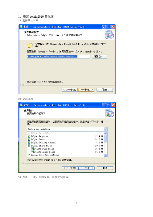
1.安装delphi2010简化版1)选择默认目录2)全选选项3)点击下一步,开始安装,直到安装完成。
2.运行delphi2010在下面界面中必须选择Yes。
进入DELPHI2010界面3.安装ehlib组件1)进入delphi2010后,打开(open Project)安装文件夹下Delphi.2010.RTM.v14.0.3513.24210.Lite.v3.6\EhLib V5.2.48的Ehlib140工程。
2)选中右边栏目中的EhLib140.bpl文件,按右键编译(compile)这个工程。
3)采用同样的方法,打开(open Project)安装文件夹下Delphi.2010.RTM.v14.0.3513.24210.Lite.v3.6\EhLib V5.2.48的DclEhlib140工程。
4)同样的,选中右边栏目中的EDclhLib140.bpl文件,按右键编译(compile)这个工程,,然后安装(install)这个工程。
安装完成后,出现下面屏幕提示:5)同样的,选中右边栏目中的myEditnum文件,按右键编译(compile)这个工程,,然后安装(install)这个工程。
安装完成后,出现屏幕提示。
6)设置路径。
在delphi2010的主菜单中的Tools+options+Library win32,点击Library Path右边的按钮,在弹出的Directories窗体中选中EhLib V5.2.48文件夹,确定后,选择Add,把吧这个文件夹添加进去。
同样方法,把EhLib V5.2.48这个文件夹下面的一个子文件夹RADStudio2010也添加(Add)进去。
7)退出DELPHI2010,并选择保存DclEhlib140和myEditnum4.安装virtualstringtree1)点击VirtualTreeviewSetup.exe文件,选择下列默认路径。
2)注意下面CodegGear RAD Studio2010必须打上钩(默认已打钩)2)3)一直安装到完成。
- 1、下载文档前请自行甄别文档内容的完整性,平台不提供额外的编辑、内容补充、找答案等附加服务。
- 2、"仅部分预览"的文档,不可在线预览部分如存在完整性等问题,可反馈申请退款(可完整预览的文档不适用该条件!)。
- 3、如文档侵犯您的权益,请联系客服反馈,我们会尽快为您处理(人工客服工作时间:9:00-18:30)。
else
ExpClass := nil; Ext := '';
end;
if ExpClass <> nil then
begin
if UpperCase(Copy(SaveDialog1.FileName,Length(SaveDialog1.FileName)-2,3)) <>
七、数据行高度
使用 RowHeight 和 RowLines 属性来指定数据行高。完整的数据行高 = 行线高度+行高。设置 RowSizingAllowed 为 True 以允许可以在运行是使用鼠标来改变行高。
设置Column.WordWrap为True可以使数据行中文本多行显示。如果行高>文本行,它就换行。
按钮式标题
设置Column.Title.TitleButton 为 True可以强制标题单元为按钮式。写 OnTitleBtnClick事件来控制用户单击标题单元时的操作。
六、标题属性的默认值
使用TDBGridEh.ColumnDefValues.Title来设置标题属性的默认值。
十、列属性的默认值
使用ColumnDefValues属性来设置列属性的默认值。新创建的列将从ColumnDefValues属性中获得属性值,并且直到第一次为其指定值为止。
2: begin ExpClass := TDBGridEhExportAsCSV; Ext := 'csv'; end;
3: begin ExpClass := TDBGridEhExportAsHTML; Ext := 'htm'; end;
4: begin ExpClass := TDBGridEhExportAsRTF; Ext := 'rtf'; end;
八、显示备注字段
设置 DrawMemoText to True来显示文本式的备注字段。.
九、定制单元格字体及颜色
TDBGridEh 中的 Font 和 Color 属性描述了数据网格中绘制单元格的字体和颜色。
TColumnEh 中的 Font 和 Color 属性描述了指定列中绘制单元格的字体和颜色。
就是那种效果了。
===============================================================
四、Ehlib 怎样固定某几列?
只要设置dbGridEh的FrozenCols属性为几列即可.
五、定制网格标题 复杂标题
TDBGridEh 允许在多列上创建标题,例如:
设置 eMultiTitle 属性为 True 并且填充字段的标签或列标题的标题,可以使用下面的规则:字段标签中的文本部分或列标题必须由几部分组成,并且用 "|" 分割,几个列的每一个通用部分都设置为相同。其它字段或标题必须在相应的部分包含同样的文本。
例如:
Field1.DisplayLabel := 'Title1|SubTitle1';
以下是EHLIB的导出代码:(其实EHLIB的DEMO1中已有)
procedure TInvoiceManager.ppmSaveSelectionClick(Sender: TObject);
var ExpClass:TDBGridEhExportClass;
Ext:String;
在对象管理器中的相关位置有设
================================================================
三、本人刚学习使用ehlib包,现在要实现类似ehlib所带demo1中一个功能:点击dbgrid某列值
的下拉按纽(可以设置),弹出一个下拉列表(其内容是另一个dataset的)。我看demo1中
事件定制单元格字体及颜色
有几个事件可以让你能够在绘制单元格前定制单元格字体和颜色。你可以写TDBGridEh的OnDrawColumnCellEvent事件句柄来在控制在网格单元中绘制数据。你可以使用Canvas属性的方法来绘制单元格。但是如果你只想改变字体或颜色的属性,我建议你使用下面的事件。你可以写TDBGridEh的OnGetCellParams事件来控制在绘制数据单元以前所指定的操作。你可以改变绘制字体及背景色。这个事件适合你在想改变整行的字体或颜色时使用。如果你想改变指定列中单元格的属性,你可以使用TColumnEh.OnGetCellParams。写这个事件用来控制在一列数据单元被重绘或编辑时的操作。在一列数据单元被重绘以前,你可以改变绘制字体,背景色,对齐方式,图像索引,文本或检查框。在编辑一列数据单元以前,你可以改变编辑字体,背景色,文本或只读状态。
ehlib v5 在delphi2010下的安装
1.卸载老版本
2.创建目录如 e:\ehlib5
3.把RADStudio2010和common 文件夹下的文件拷贝到 e:\ehlib5下
4.如需要,把e:\ehlib5加入到lib:
Tools->Options->Delphi Options->Library - Win32->Library Path).
// 引用:
// 例如:DbGridEhFoot( DbGridEh1, ´Number,Sum´, fvtSum ); 设定数量和金额字段为合计统计
//--------------------------------------------------------------------------------
Field2.DisplayLabel := 'Title1|SubTitle2';
或
DBGridEh.Columns[0].Title.Caption := 'Title1|SubTitle1';
DBGridEh.Columns[1].Title.Caption := 'Title1|SubTitle2';
if tmpFldList.IndexOf( uppercase( cFieldName ) ) >= 0 then
begin
pDbGrid.Columns[nFldLoop].Footer.ValueType := pvtType ; // 统计类型
end;
end ;
tmpFldList.Free ;
end;
一、如何在程序中确定Ehlib定义的报表表头颜色?
在执行打印之前,加上下面的语句:
DBGridEh1.FixedColor:=clLime;//clLime可以换成你想要的颜色比如clRed是红色等等
PrintDBgridEh1.Options:=[pghColored,pghFitingByColWidths];//方括号里的"pghColored"是必需的,其它的根据你的需要决定取舍
StrToStringList( Uppercase(pcFields),´,´,tmpFldList ); // 将字符串转换为串列表
For nFldLoop := 0 to pDbGrid.Columns.Count -1 do
begin
cFieldName := pDbGrid.Columns[nFldLoop].FieldName ; // 网格列字段名
================================================================
二、Ehlib中的PrintDBGridEh如何印页码,即第几页共几页
PrintDBGridEh1.PageFooter.CenterText:='第&[Page]页 共&[Pages]页'
Procedure DbGridEhFoot( pDbGrid:TDBGridEh; pcFields: string; pvtType : TFooterValueType );
var nFldLoop : integer ;
cFieldName : string ;
tmpFldList : TStrings ;
好象是使用了DBLookupComboboxEh,可我参看demo1怎么设置也不行,请指教。谢谢。
呵呵,这个效果没有用DBLoookupComboBoxEh,它是利用查找字段实现的。
它在Query1中,对应VName字段,增加了一个叫VName1的查找字段,这个
字段从qrVendors查找相关的数据,再在DBGridEh1显示VName1,这样显示
end;
end;
end;
// 功能:设定 DbGridEh 合计行信息
// 参数: pDbGrid:TDBGridEh;
// pcFields : string ; 字段列表,字段用逗号分隔
// pvtType : TFooterValueType ; 统计类型 TFooterValueType = (fvtNon, fvtSum, fvtAvg, fvtCount, fvtFieldValue, fvtStaticText);
5.用 "File\Open..." 打开EhLib140.Dpk,并编译;
然后打开EhLibDataDriversXX.Dpk,并编译;
