马来西亚松下风扇马达 MHAA
Panasonic 车用冷却风扇马达商品简介(中文版)

⑤溫溼度試驗機 * 2 ⑥高溫試驗機 * 2
⑥
⑦噪音測定室
⑧N-T性能測試機
③
③
④
⑤
⑤
Panasonic DC Flat Motor Series
2-wheeled use SSW6 30mm 2-wheeled use SSW7 37mm 2-wheeled, 4-wheeled use SSW95(2耳),97LS(3耳) 37mm 37mm 2-wheeled, 4-wheeled use SSW97LM 37mm 2-wheeled, 4-wheeled use SSW97LW 37mm ATV use SSW9V 37mm
跟有矽鋼片式薄型馬達 松下馬達有以下几個優點 1. 薄 2. 輕量化 3. 低EMC雜訊
馬達結構與扭力輸出範圍
扭力與入力範圍 結構分析 9700LW 型
0.4
磁石 (雙)
0.3
TORQUE [N m] ・
9700LW Type
0.2
電機子 整流子
碳刷覆蓋 (Phenol plastic)
9700LS Type
φ62
φ30
Appearance Measurements
φ99
φ99
Shaft diameter:φ7 diameter:φ7Shaft diameter:φ7 Shaft
Shaft diameter:φ7 12 91 0.2 3000 7.6 68
φ99
Shaft diameter:φ7 12 101 0.25 2500 8.4 64 12 90 0.25 2280 7.5 65 12 84 0.25 2040 7 62 12 73 0.25 1640 6.1 58
Neatafan VH1 to VH5 Electric Heater Product Manual
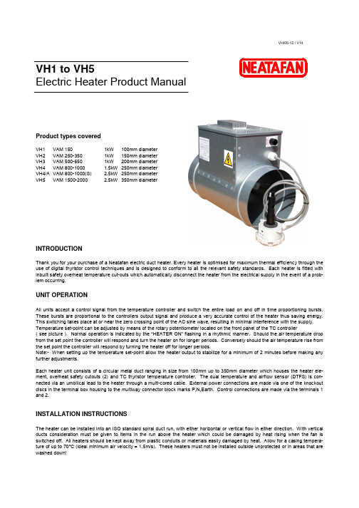
VH1 to VH5Electric Heater Product ManualProduct types coveredVH1 VAM 1501kW 100mm diameter VH2 VAM 250-350 1kW 150mm diameter VH3 VAM 500-650 1kW 200mm diameter VH4 VAM 800-1000 1.5kW 250mm diameter VH4/A VAM 800-1000(S) 2.5kW 250mm diameterVH5 VAM 1500-20002.5kW350mm diameterINTRODUCTIONThank you for your purchase of a Neatafan electric duct heater. Every heater is optimised for maximum thermal efficiency through the use of digital thyristor control techniques and is designed to conform to all the relevant safety standards. Each heater is fitted with inbuilt safety overheat temperature cut-outs which automatically disconnect the heater from the electrical supply in the event of a prob-lem occurring.UNIT OPERATIONAll units accept a control signal from the temperature controller and switch the entire load on and off in time proportioning bursts. These bursts are proportional to the controllers output signal and produce a very accurate control of the heater thus saving energy. This switching takes place at or near the zero crossing point of the AC sine wave, resulting in minimal interference with the supply. Temperature set-point can be adjusted by means of the rotary potentiometer located on the front panel of the TC controller( see picture ). Normal operation is indicated by the “HEATER ON” flashing in a rhythmic manner. Should the air temperature drop from the set point the controller will respond and turn the heater on for longer periods. Conversely should the air temperature rise from the set point the controller will respond by turning the heater off for longer periods.Note:- When setting up the temperature set-point allow the heater output to stabilize for a minimum of 2 minutes before making any further adjustments.Each heater unit consists of a circular metal duct ranging in size from 100mm up to 350mm diameter which houses the heater ele-ment, overheat safety cutouts (2) and TC thyristor temperature controller. The dual temperature and airflow sensor (DTFS) is con-nected via an umbilical lead to the heater through a multi-cored cable. External power connections are made via one of the knockout discs in the terminal box housing to the multiway connector block marks P,N,Earth. Control connections are made via the terminals 1 and 2.INSTALLATION INSTRUCTIONSThe heater can be installed into an ISO standard spiral duct run, with either horizontal or vertical flow in either direction. With vertical ducts consideration must be given to items in the run above the heater which could be damaged by heat rising when the fan is switched off. All heaters should be kept away from plastic conduits or materials easily damaged by heat. Allow for a casing tempera-ture of up to 70°C (ideal minimum air velocity = 1.5m/s). These heaters must not be installed outside unprotected or in areas that are washed down!VH/05-12 / V14Warning:- When used in VAM installations keep a minimum of 2 metres of duct from the heater to the VAM unit.To install the heater, measure between the swaged rings and cut the spiral to suit. Use high temperature sealant and pop rivets to fix. Do not use flexible connectors directly onto the heater. The best position for the terminal box is on the side of a horizontal duct. Ensure access to the terminal box is possible! Make sure lagging etc. does not cover the terminal box.DTFS sensor - the combined temperature and airflow sensor will be found attached to a coiled lead. This should be mounted in the duct a minimum of 1.5 metres downstream from the heater or in a downstream position where the sensor cannot be damaged by heat. A 25mm hole saw will be required. Mount the sensor in the duct using 2 x PK self tapping screws ensuring correct orientation for the direction of airflow as indicated by the airflow arrow on the sensor.The sensor thermistor detects duct air temperature which is then compared to the set point temperature on the TC controller front panel which in turn controls the amount of power supplied to the heater elements. The MEMS airflow sensor is mounted on the tip of the probe tube and this senses the airflow. This feeds a control signal back into the TC controller to allow the heater to turn ON when an airflow is detected.VAM REMOTE CONTROLLER SETTINGS18 – 3 – 02 Must be activated to enable X15 output.19 – 8 – 03 Must be activated to enable fan delay.WIRINGAll wiring must be carried out by a qualified electrician in compliance with the latest regulations.These units are internally pre-wired and require only a suitable supply feed connection to operate (see rating label).Care must be taken to ensure that incoming mains rated wiring entering into the heater terminal box must be routed away from any potential hotspots by using cable supports and cleats where needed. An appropriately sized cable gland should be used to protect the incoming power cables at the point of entry into the terminal housing.SAFETYEvery electrical system should have an isolator switch which can be locked in the “off” position to prevent accidental reconnection during maintenance. A suitably rated MCB should be included in the mains supply circuit to the heater as follows:1kW and 1.5kW rated output – 10 Amp MCB2.5kW rated output – 16 Amp MCBEvery heater is fitted with a manual reset (T13) and an automatic reset (T14) thermal cutout switch which are connected in series with element heater (max. 3kW) and control circuit. The object of these switches is to disconnect the heater in the event of airflow failure and prevent a dangerous build-up of heat.Note:- When resetting the manual reset thermal cutout, the heater may suddenly switch on and element terminals etc. will become live. Ensure the heater is correctly earth bonded. Terminal covers must be secured after inspection and should be labeled “DISCONNECT SUPPLY BEFORE REMOVING THIS COVER”. It is the installer’s responsibility to ensure the installation meets all current Health & Safety Regulations.The heater must not be used by children or persons with reduced physical, sensory or mental capabilities, or lack of experience and knowledge, unless they have been given supervision or instruction.EMC & LVD COMPLIANCEAll Neatafan heaters and controls have been designed and tested to ensure conformance with the EMC Directive 2004/108/EC and LVD directive 2006/95/ECWARRANTYNeatafan heaters are warranted against faulty or bad workmanship. This offer is conditional upon the heater being operated within the designed safe working limits.WEEE DIRECTIVENeatafan Limited does not supply a “complete” product, only components that are incorporated into a fixed installation, therefore falls outside the scope of the directive.At the end of its useful life the product should be disposed of via a suitable recycling centre.Do not dispose of with normal household waste.TC7 TEMPERATURE CONTROLLERThe TC7 unit acts as a thyristor temperature control panel to control a 220/250V single phase heater up to 19A (4.5kW) and has 5A fused outputs for single phase supply and extract fans up to a maximum of 4.5A each.FIG.1 FIG.2 REAR(PCB) FRONTSPECIFICATION Supply voltage 220/250Vac 50/60Hz. +/-10% Output current (maximum) 19A @ 40ºC (Ambient) Temperature sensor 5k ohms @ 25ºC (Table 502 IT) Temperature control range 0 to 40ºC / (0-10V 0-100%) Supply Fan outputs (5A fused) 4.5A max FLC. Extract Fan outputs (5A fused) 4.5A max FLC. Run on timer adjustable from 1 to 2 minutes (factory set at 1.5 minutes) Control fuse 20 x 5mm 250mA LED Indicators Power On – Yellow Supply Fan On – Green Extract Fan On – Green Heater On – Red (solid or flashing, indicating pulsed control) Airflow Fault – Red Dimensions Front Panel 114mm x 197mm x 2mm thick aluminium Heat Sink 55mm x 100mm x 20mm thick aluminium PCB 85mm x 165mm Mounting holes 98mm x 181mm centres 5mmØ holes Maximum ambientadjacent to terminal box 35ºC (during operation) Auto High Temp Cutout 100ºC Pre-set Man. Reset High Temp Cutout 125ºC Pre-set Run Rly 1A 120V AC or 1A 24V DC ALT SP0-10V DCPower TerminalsFig.3To “ X15 “Control Input TerminalsThese are a pair of 220/250V input connections normally used to switch the heater unit ON. These contacts are used to con-nect to the VAM X15A Board, via the terminal block (1-2 in Fig.3)To connect the power supply 220/250Vac 50/60Hz to Earth, P and NNEATAFAN LimitedUnit 12 • Solent Industrial Estate • Shamblehurst Lane • Hedge End • Southampton • Hampshire • SO30 2FXTel:+44(0)1489783783•Fax:+44(0)1489788048•Email:*****************.ukBMSRun RlyThis is a volt free switched relay output which closes to indicate if the unit is healthy when the temperature sensor is connected and airflow has been established.ALT SP - Alternate Setpoint TerminalsThese terminals are provided for an external 0-10V DC signal to control the heater output remotely via a BMS or other form of temperature controller.Use of these terminals overrides the temperature setpoint and controls the thyristor 0-100% / 0-10V DC when the ‘P’ ‘T’ Jumper is set to the ‘P’ position. (see figs 4 & 5) i.e.5V = 50% output. IMPORTANTWith the Jumper in the ‘P’ position the temperature setpoint must be set to 0ºC on the front panel.Jumper ‘T’ Position fig.4Jumper ‘P’ Position fig.5(set as standard)(set for 0-10V BMS InputØ AMODEL kW A B C D E H L VH1 1.0 100 80 115 250 75 207 400 VH2 1.0 150 80 135 250 75 257 400 VH3 1.0 200 80 180 250 75 307 400 VH4 1.5 250 80 180 250 75 357 400 VH4/A 2.5 250 80 180 250 75 357 400 VH52.535080 18025075 457400DIMENSIONS (mm)TITLE:BY:DATE:PAGE:21/05/20121/1REV:NFE+-E X T S S RN N E R U N -O NALT S/PL N L NE X TF A NS U P F A NL I V EL O A DPTJUMPERRUN RUN RLY(HV)TC7CONTROLLERTRIM RESCUTOUTMANUAL RESETBLACK WHITEGREEN BLUE PINKEP NHEATER220V/250Vac 50/60HzDTFSCOMBINED AIRFLOW & TEMPERATURE SENSORBROWN 1.5mmB L U E 1.5m mB R O W N 1.5m mG R E E N /Y E L L O W 2.5m mTYPE 13YELLOWYELLOW AUTO RESET CUTOUT TYPE 14X15A BOARD2M LEADSEE *NOTES* FOR VAM CODE SETTINGSVAM*NOTES*1) CODE 19-8-03 TO BE SET AT REMOTE CONTROLLER TO ALLOW FAN RUN-ON FOR ELECTRIC HEATER USE 2) CODE 18-3-02 TO BE SET TO ENABLE X15A VOLTAGE OUTPUT AND HEATER OPERATIONWIRING FOR VAM ELECTRIC HEATERS.12EARTH P NA。
B2-SAYEY1G88BA0B0A

Datasheet of SAW Device SAW Duplexerfor Band2 / Unbalanced / LR /1814 Murata PN:SAYEY1G88BA0B0A⏹Featurefor LTELow I.LHi IsoNote : Murata SAW Component is applicable for Cellular /Cordless phone (Terminal) relevant market only.Please also read caution at the end of this document.- Operating temperature- Storage temperature- Input Power- D.C. Voltage between the terminals- Minimum Resistance betweem the terminals - RoHS compliance : -20 to +85 deg.C: 1M ohm: 3V (25+/-2 deg.C): Yes: +29 dBm 5000 h 50 deg.C : -40 to +85 deg.CPackage Dimensions & Recommended Land Pattern unit: mmLand PatternMeasurement Circuit (Top View)R1 : 50 ohmR2 : 50 ohmR3 : 50 ohmElectrical Characteristic< TX→ANT. >Electrical Characteristic< ANT.→RX. >Electrical Characteristic< TX→RX. >Electrical Characteristic< TX→ANT. >Electrical Characteristic< ANT.→RX. >Electrical Characteristic< TX→RX. >Dimensions of Tape & Reel unit: mmCarrier TapeA: 8.0 J: 1.7 B: 1.75 K: 2.1 C: 3.50 L: 0.70 D: 4.0 E: 2.00 F: 4.0 G: φ1.5 H: 1.00ReelSAYEY1G88BA0B0AR00… 10000pcs (φ330) SAYEY1G88BA0B0AR05… 5000pcs (φ330) SAYEY1G88BA0B0AR1S… S ample Order (φ178)φ178Reel φ330Reel A: φ13.0 A: φ13.0 B: 13.5max B: 15.5max C: 9.0 C: 9.5 D: φ60 D: φ100 E: φ178 E: φ330Table B: Date Codedate1st2nd3rd4th5th6th7th8th9th10thcode A B C D E F G H J KImportant Notice (1/2)PLEASE READ THIS NOTICE BEFORE USING OUR PRODUCTS.Please make sure that your product has been evaluated and confirmed from the aspect of the fitness for the specifications of our product when our product is mounted to your product.All the items and parameters in this product specification/datasheet/catalog have been prescribed on the premise that our product is used for the purpose, under the condition and in the environment specified in this specification. You are requested not to use our product deviating from the condition and the environment specified in this specification.Please note that the only warranty that we provide regarding the products is its conformance to the specifications provided herein. Accordingly, we shall not be responsible for any defects in products or equipment incorporating such products, which are caused under the conditions other than those specified in this specification.WE HEREBY DISCLAIMS ALL OTHER WARRANTIES REGARDING THE PRODUCTS, EXPRESS OR IMPLIED, INCLUDING WITHOUT LIMITATION ANY WARRANTY OF FITNESS FOR A PARTICULAR PURPOSE, THAT THEY ARE DEFECT-FREE, OR AGAINST INFRINGEMENT OF INTELLECTUAL PROPERTY RIGHTS.The product shall not be used in any application listed below which requires especially high reliability for the prevention of such defect as may directly cause damage to the third party's life, body or property. You acknowledge and agree that, if you use our products in such applications, we will not be responsible for any failure to meet such requirements.Important Notice (2/2)Furthermore, YOU AGREE TO INDEMNIFY AND DEFEND US AND OUR AFFILIATES AGAINST ALL CLAIMS, DAMAGES, COSTS, AND EXPENSES THAT MAY BE INCURRED, INCLUDING WITHOUT LIMITATION, ATTORNEY FEES AND COSTS, DUE TO THE USE OF OUR PRODUCTS IN SUCH APPLICATIONS.- Aircraft equipment.- Aerospace equipment- Undersea equipment.- Power plant control equipment - Medical equipment.- Transportation equipment (vehicles, trains, ships, elevator, etc.).- Traffic signal equipment.- Disaster prevention / crime prevention equipment.- Burning / explosion control equipment- Application of similar complexity and/ or reliability requirements to the applications listed in the above.We expressly prohibit you from analyzing, breaking, Reverse-Engineering, remodeling altering, and reproducing our product. Our product cannot be used for the product which is prohibited from being manufactured, used, and sold by the regulations and laws in the world.We do not warrant or represent that any license, either express or implied, is granted under any our patent right, copyright, mask work right, or our other intellectual property right relating to any combination, machine, or process in which our products or services are used. Information provided by us regarding third-party products or services does not constitute a license from us to use such products or services or a warranty or endorsement thereof. Use of such information may require a license from a third party under the patents or other intellectual property of the third party, or a license from us under our patents or other intellectual property.Please do not use our products, our technical information and other data provided by us for the purpose of developing of mass-destruction weapons and the purpose of military use.Moreover, you must comply with "foreign exchange and foreign trade law", the "U.S. export administration regulations", etc.Please note that we may discontinue the manufacture of our products, due to reasons such as end of supply of materials and/or components from our suppliers.Customer acknowledges that Murata will, if requested by you, conduct a failure analysis for defect or alleged defect of Products only at the level required for consumer grade Products, and thus such analysis may not always be available or be in accordance with your request (for example, in cases where the defect was caused by components in Products supplied to Murata from a third party).The product shall not be used in any other application/model than that of claimed to Murata.Customer acknowledges that engineering samples may deviate from specifications and may contain defects due to their development status.We reject any liability or product warranty for engineering samples.In particular we disclaim liability for damages caused by・the use of the engineering sample other than for evaluation purposes, particularly the installation or integration in the product to be sold by you,・deviation or lapse in function of engineering sample,・improper use of engineering samples.We disclaim any liability for consequential and incidental damages.If you can’t agree the above contents, you should i nquire our sales.。
DC无刷马达VS一般AC调速马达
DC無刷馬達V.S 一般AC調速馬達最普遍的動力來源,非屬馬達不可! 市面上的AC感應式馬達,由於本身具備構造簡單、操作容易、成本低等優點,但相對的也有其缺點存在,例如:馬達效率低、溫昇高、振動大、噪音大、低轉速時控制不容易等缺點。
相較之下,具備高效率、省電、節能減碳等特點的DC無刷馬達,因而廣泛被使用於工業動力上,很多使用者積極將AC馬達汰換為DC無刷馬達,使用的人比例也越來越高,不僅可以有效改善使用AC馬達時所遇到的問題,又能減少使用上安全顧慮的問題(如火災、人為疏失等),此外,「地球暖化」一直是全球關注的議題,使用高轉換效率的DC無刷馬達,能夠節省不少的電費,不僅省錢也可以落實節能減碳的目的,共同落實保護地球的使命!【AC馬達V.S DC無刷馬達-優缺點簡介】AC馬達-優點◎結構簡單◎生產容易、無接觸零件較不用保養使用期限長、維修容易、使用簡單◎轉速與頻率成正比◎頻率愈高轉速愈快◎成本低AC馬達-缺點◎高速控制不方便◎速度控制須改變頻率或加裝其他回授器較麻煩,此外,轉速受電源頻率固定,無法做高速運轉,需搭配變頻器來做調速但卻容易產生振動、噪音、雜訊干擾,溫昇等問題,轉速不穩定,即使可與全頻段變速平穩低噪音的變頻器做使用,以改善問題,卻因此增加成本◎有接點控制◎需另外使用繼電器,配線耗時,須定時維修DC無刷馬達-優點◎轉矩特性優異>啟動轉矩大,啟動快,從低速到高速可保持穩定的速度與轉矩,控制簡單,啟動電流小,可低速大功率運行,並省去減速機直接驅動大的負載,具有強大的負載能力◎響應速度快>速度調整容易,運轉平順,緩啟緩停、控制特性好,可省去原有的機械制動或電磁制動裝置;不受電源頻率限制,亦可做高速運轉◎調速範圍寬可做250-3000RPM的調速,電壓,轉速與外加電壓成正比,轉速可以線性化控制,節省能源,體積小,重量輕◎無接點控制>可直接搭PLC,配線簡單,無火花免保養,不需要花大錢去做保養或修理的動作,磨損、故障率低,只需要更換培林就可以繼續使用,溫昇低,無須搭配風扇,適用於無塵室,使用壽命長◎雜訊少>電氣雜訊干擾少,火花相對少,可靠度高,耐顛簸震動,噪音低,特別適合爆炸性場所、高溫環境◎適用於頻繁性正逆轉操作、多段速度變化◎電子式換相>取代傳統的機械換相,提高轉換效率、性能可靠、穩定性高DC無刷馬達-缺點◎低速起動時易有輕微振動,易形成共振◎需搭配驅動器才能做使用◎雖然速度變動率低,但無法做精密定位控制◎成本較高【DC無刷馬達V.S一般AC調速馬達】一、DC無刷馬達—高效率、省電DC無刷馬達由左圖可知,當提供100%的電源入力給無刷馬達時,僅會有15%~20%的損失形成熱,其他80%~85%會轉換成機械能來做使用,由此可知,無刷馬達大約有將近80%~85%的轉換效率,此外,無碳馬達透過非接觸式的位置檢知器與半導體元件,以取代傳統DC有刷馬達整流子換相的問題,藉由電子式的換相,免除了碳刷摩耗及壽命的問題,少了電刷和整流子的摩擦,相對也會比較省電和安靜,也不會有火花的問題,而轉子由永久磁石構成,磁場大、效率高,增加運轉穩定性,具備有高效率、省電、省能源的優良優點,此外,無碳刷切換的問題,也沒有因碳刷摩擦所產生的熱,使得馬達不易有溫昇的情況,透過無刷馬達良好的轉換效率,有效使用能源,減少因損失所產生的熱,更能達到”節能減碳”的目標。
松下案例分析

• • • • • • • • • • • • • •
在前辈描绘未来 美丽的梦想里飞翔 今天我们要奋飞 张开翅膀 我们坚信凭借 先进的科学创造幸福 未来终将会实现 我们新的梦想 每个人点点的希望之光 聚集在一起 闪烁灿烂的光芒 Let’s get to together at Panasonic 携手世界去开创 卓越技术的更辉煌
人生的五个阶段
• 快乐的童年 1894年出生于日本和歌山县,他 是家里八个孩子中年龄最小的 • 学徒磨练 1904年,9岁的幸之助开始了他长 达15年的学徒生涯。 • 创业初期 1918年幸之助以插座起家,创立松 下电器具制作所。1927年,日本爆发银行危机 , 松下面临巨大考验 • 重新起步和腾飞 1932年,幸之助提出了著名的 “自来水哲学”。1961年,66岁的幸之助宣布辞 去社长,改任会长 • 致力于社会公益 1968年开始,幸之助置身于捐 赠、慈善等公益活动,这几乎花费了他的所有时间 和大部分财力
堤坝式经营
• 堤坝式经营的实质,是避免经营过程中的 周期性震荡,减少不确定性对企业的冲击。 经营过程中需要建立的堤坝主要有: • >设备堤坝 >库存堤坝 • >资金堤坝 >产品堤坝 • >心理堤坝
玻璃式经营
• “玻璃式经营”的要旨是公开和透明。这种 公开和透明,建立在对员工信任的基础之 上。所有的经营状况,都像玻璃一般清澈 可见,不加掩饰。
“人是万物之王”
• 松下幸之助强调,松 • 松下注重维系人心, 下公司的最大产品是 采取精神与物质结合 人。好的企业,应该 的激励办法。看似寻 在出产品前先出人才, 常的发动职工提供建 在制造产品前先培养 议的制度,在松下公 人才,“造人”先于 司却有它的独到之处, “造物”。 实施的效果非常好, 极大地发挥了广大员 工的潜能。
松下伺服电机A5与电机选型
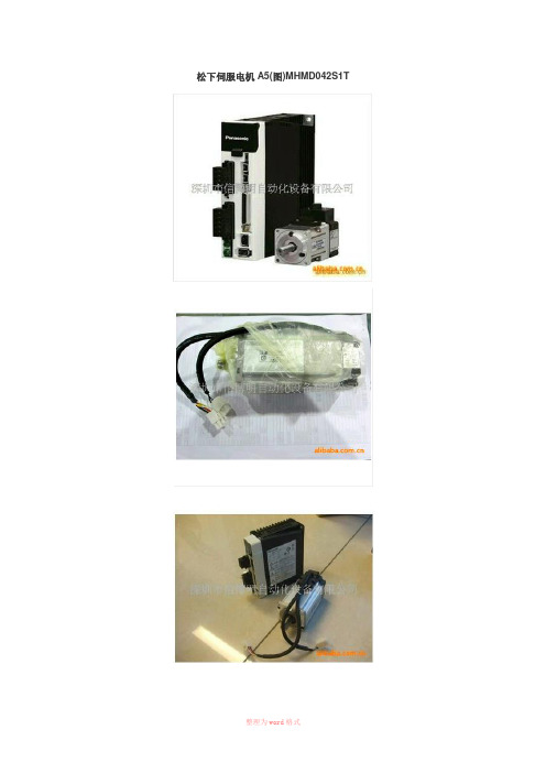
松下伺服电机A5(图)MHMD042S1T松下开发出了响应性更高的AC伺服马达“MINAS-A5”系列(图)。
响应频率较原来的1kHz提高了1倍,达到2kHz。
嵌入制造半导体及液晶时使用的贴片机、探针及电子部件封装机等装置后,能够使可动部迅速起动或停止。
另外还对降低振动下了一番工夫,有助于缩短制造装置的单件产品生产时间。
为了抑制振动,首先将转子的极数增至10,减小了齿槽力矩。
其次,通过内置共振抑制滤波器和减振滤波器,将振动降到了原来的1/8。
而且还在轻量化方面改进了转子和定子的设计和工艺,使重量比原来减轻了10~25%。
此外,易用性也得到了提高。
此次开发了可简单进行装置起动作业的装配支持用软件。
支持日语、英语、汉语及韩语4种语言,海外工厂的员工也可轻松操作。
符合防水规格IP67,耐水性及耐油性也很出色。
电压根据输出功率备有100V、200V、400V三种。
最大转速为6000rpm (但在750W以下)。
输出功率范围为50W~15kW。
其中,5kW以下型号从2009年9月1日开始销售,超过5kW的型号将于2010年春季上市。
A5系列电机的特点:功率: 50W~5kW 惯量不同特性改善:槽定位转矩0.5%以下小型?超轻化:行业最轻(1kW~5kW)高分解率:绝对式17bit、增量式20bit耐环境性能升级: IP67构造连接:全容量连接化A5系列驱动器的特点电源:单相AC100V、单/3相AC200V控制模式:转矩、速度、位置、全闭环控制参数:扩大自动设定范围与PC通信:对应USB 新软件设定,操作性能升级安装:与A4互换松下伺服电机MINAS A5系列产品:1、实现行业最快的速度响应频率2.0KHz通过独家开发的全新LSI提高运算速度,同时配备基于转矩前馈的高响应控制功能。
采用行业最快的速度和定位响应性,是最快速的装置。
另外响应延迟性低,并将振动降低到最低限度。
采用独特的信号处理技术,开发出全新的104万脉冲20bit编码器;通过采用电机转子的10极化、磁场解析技术的全新设计,减小了脉动宽度,实现了行业最小的低齿槽,且通过提高速度稳定性和电机旋转位置来减少转矩变化,从而大幅提高了定位的稳定性;指令输入反馈输出都实现了4Mpps的高速对应,包括标准对应的全闭环在内,都可实现高分辨率运转及高速运转。
松下伺服马达A5的性能特点
松下伺服马达A5的性能特点据日弘忠信了解,松下伺服马达A5是目前国内用得最多、需求量最大、市场覆盖率最高的伺服产品之一,这是因为它具有超高速响应、智能化、更轻巧、使用方便、安全等级高等优势,在此,我们主要介绍其安全等级。
松下伺服马达A5的畅销离不开其安全等级更高的特性,松下A5系列伺服电机的安全等级达到IP67标准。
采用与电机电源、编码器输入输出部直接连接的连接器,使电机的密封性得以提高,达到IP67标准,同时电机的耐环境性也更高。
安全等级IP67,6的意思是防异物,防止因完全接触而侵入灰尘;7是防水,对规定压力时间内的渗水进行保护。
2013年9月,松下公司又推出松下A52伺服电机系列,其性能更高过A5系列电机。
松下伺服马达A5拥有良好的速度控制特性,整个速度区内可实现平滑控制,几乎无振荡;高效率,90%以上,不发热,高速控制。
高精确位置控制(取决于何种编码器),额定运行区域内,实现恒力矩,低噪音,没有电刷的磨损,免维护,不发生磨损颗粒、没有火花,适用于无尘间、易暴环境。
伺服主要靠脉冲来定位,基本上可以这样理解,松下伺服马达A5接收到1个脉冲,就会旋转1个脉冲对应的角度,从而实现位移,因为,伺服电机自身具备发出脉冲的功能,所以伺服电机每旋转一个角度,都会发出对应数量的脉冲,这样,和伺服电机接受的脉冲形成了呼应,或者叫闭环,如此一来,系统就会知道发了多少脉冲给伺服电机,同时又收了多少脉冲回来,这样,就能够很精确的控制电机的转动,从而实现精确的定位,可以达到0.001mm伺服电机内部的转子是永磁铁,驱动器控制的U/V/W三相电形成电磁场,转子在此磁场的作用下转动,同时电机自带的编码器反馈信号给驱动器,驱动器根据反馈值与目标值进行比较,调整转子转动的角度。
深圳市日弘忠信电器有限公司是一家集品牌代理、产品配套、解决方案、工程服务于一体的运营服务商。
公司秉承“共赢发展,忠信为本”的经营理念,自成立以来,不断引入欧、日、台及国内名优品牌工业自动化产品,服务于广大自动化机械设备厂商,在业内拥有较高知名度。
Panasonic 交流伺服马达-驱动器 MINAS A5系列说明书

使用说明书(基本篇)交流伺服马达·驱动器MINAS A5系列1.开封确认 (2)开箱拆封后,请确认 (2)确认驱动器型号 (2)确认电机型号 (3)2.设置方法 (4)驱动器 (4)电 机 (6)3.系统结构和配线 (8)总配线图(主电路连接器型) (8)总配线图(主电路端子台型) (10)驱动器外设清单 (12)主电路(连接器)的配线要点 (14)主电路(端子台)的配线要点 (16)连接器的接线方法 (17)主电路配线图 (19)电机、制动器连接器的连接 (21)连接器X1的配线 (22)连接器X2的配线 (22)连接器X3的配线 (23)连接器X4的配线 (24)连接器X5的配线 (27)连接器X6的配线 (28)连接器X7的配线 (30)4.参数和模式的设定 (31)概要.设定.连接 (31)参数的构成 (33)5.保护功能 (34)保护功能(错误码) (34)6.保养.检查 (36)7.欧洲EC标准/对应UL标准 (38)外设构成 (40)8.电机内置保持制动器 (44)9.动态制动器 (46)10.确认驱动器和电机的配套型号 (47)20位 增量式规格 (47)17位 绝对式规格 (48)11.规 格 (49)12.质量保证 (52)售后服务(修理) (53)页页■目录铭牌内容型号说明型号说明M A D H T15功率器件的最大额定电流机架型号75~61~4例:09040001N流水号制造月份制造年(2位数)例:20090401生产日生产月历)*2 键槽及轴端中心螺纹孔具有标准产品和订购产品两种。
详情请咨询销售店。
●…与您所定购的型号是否相符?●…在运输途中是否有损伤?●…操作说明书(安全篇)是否在内?●…是否附带电源连接器、电机连接器、外置再生放电电阻连接器(仅E型附带)、…安全分流插头?…※F型未附带电源连接器、电机连接器。
铭牌内容例:P0*******N制造编号(序列号)流水号制造月份(2位数)例:20090401生产日生产日生产月历)请正确安装驱动器和电机,以免发生故障和事故。
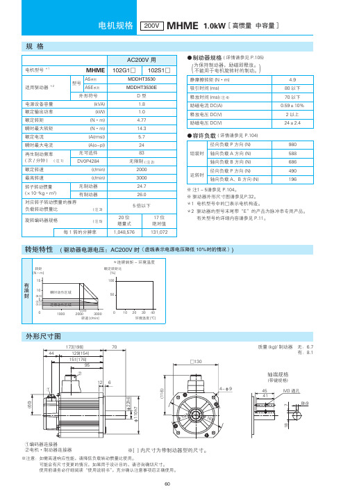
松下电机MHME系列样本
Ą<> Юࡆࠩ˝ࣛ҃Ү٧ۋᄉࡆࠩnj
※注意:如需高速响应性能,请降低负载转动惯量比使用。 可能会有尺寸变更的情况,如果用于设计目的,请咨询确切尺寸。 使用前请务必仔细阅读“使用说明书”,充分确认注意事项后正确使用。
60
电机规格 200V MHME 1.5kW[高惯量 中容量]
静摩擦转矩 (N·m) 吸引时间 (ms)
24.5 以上 80 以下
外形符号
F型
电源设备容量
(kVA)
4.5
额定输出功率
(kW)
3.0
额定转矩
(N·m)
14.3
瞬时最大转矩
(N·m)
43.0
额定电流
(A(rms))
16.0
释放时间 (ms)( 注 4) 励磁电流 DC(A) 释放电压 DC(V) 励磁电压 DC(V)
<>
ŀ
Ŀ
ƾ
´器 无:16.0 有:19.2
ᣈቪಪ
ࣛ᪃ಪ
.ߗ
I
Ŀᎃᆉ٧ᤋଋ٧ ŀႂe҃Ү٧ᤋଋ٧
Ą<> Юࡆࠩ˝҃Ү٧ۋᄉࡆࠩnj
※注意:如需高速响应性能,请降低负载转动惯量比使用。 可能会有尺寸变更的情况,如果用于设计目的,请咨询确切尺寸。 使用前请务必仔细阅读“使用说明书”,充分确认注意事项后正确使用。
61
电机规格 200V MHME 2.0kW[高惯量 中容量]
规格
电机型号 *1
MHME
适用驱动器 *2
A5系列 型号
A5E系列
外形符号
电源设备容量
(kVA)
额定输出功率
(kW)
额定转矩
英国Staffa马达 HMB系列
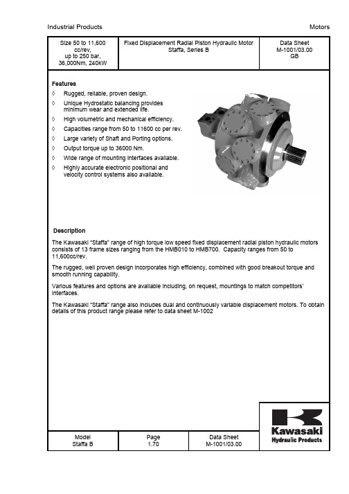
Size 50 to 11,600cc/rev, up to 250 bar, 36,000Nm, 240kW Fixed Displacement Radial Piston Hydraulic MotorStaffa, Series BData Sheet M-1001/03.00GBFeatures ◊ Rugged, reliable, proven design. ◊ Unique Hydrostatic balancing provides minimum wear and extended life.◊ High volumetric and mechanical efficiency. ◊ Capacities range from 50 to 11600 cc per rev. ◊ Large variety of Shaft and Porting options. ◊ Output torque up to 36000 Nm.◊ Wide range of mounting interfaces available. ◊Highly accurate electronic positional and velocity control systems also available.DescriptionThe Kawasaki “Staffa” range of high torque low speed fixed displacement radial piston hydraulic motors consists of 13 frame sizes ranging from the HMB010 to HMB700. Capacity ranges from 50 to 11,600cc/rev.The rugged, well proven design incorporates high efficiency, combined with good breakout torque and smooth running capability.Various features and options are available including, on request, mountings to match competitors’ interfaces.The Kawasaki “Staffa” range also includes dual and continuously variable displacement motors. To obtain details of this product range please refer to data sheet M-1002Model Staffa B Page 1.70 Data Sheet M-1001/03.00Shaft OptionsMOTOR TYPE SHAFT DESCRIPTIONHMB010 P* = Parallel keyed shaft Ø 40mmHMB010 S* = Involute spline 13 teeth BS3550HMB030/045 (H)S* = Involute spline 17 teeth to BS3550HMB030/045 (H)P = Parallel keyed shaft Ø 55mmHMB030/045 (H)Z* = Involute spline to DIN5480 (W55x3x17x7h) HMB045 Q* = Internal involute spline 21 teeth to BS3550 HMB060/080/100 (H)P* = Parallel keyed shaft Ø 60mmHMB060/080/100 (H)S* = Involute spline14 teeth to BS3550HMB060/080/100 (H)Z* = Involute spline to DIN5480 (W70x3x22x7h) HMB060/080/100 (H)Q* = Internal involute spline 24 teeth to BS3550 HMB060/080/100/125/150/200/HMB270/325 T* = Long tapered keyed shaftHMB060/080/100/270/325 X* = Short tapered keyed shaftHMB125/150/200/270/325 (H)P1* = Parallel keyed shaft Ø 85mmHMHDB125/150/200/270 & 325 (H)P2* = Parallel keyed shaft Ø 100mmHMB125/150/200/270/325 (H)S3* = Involute spline 20 teeth to BS3550HMB125/150/200 (H)S4* = Involute spline 16 teeth at 200HMHDB125/150/200, 270/325 (H)S5* = Involute spline 23 teeth to BS3550HMB125/150/200 (H)Z3* = Involute spline to DIN5480 (W85x3x27x7h) HMHDB125/150/200 (H)Z5* = Involute spline to DIN5480 (W100x4x24x7h) HMHDB125/150/200/270/325 (H)Q* = Internal involute spline 34 teeth to BS3550 HMHDB125/150/200/270/325 (H)X* = Short taper, keyed shaftHMB270/325 + HMHDB270/325 (H)Z* = Involute spline to DIN5480 (W100x4x24x7h) HMHDB400 P* = Parallel shaft with two keys Ø 100mm HMHDB400 S* = Involute spline 23 teeth to BS3550 HMHDB400 Z* = Involute spline to DIN5480 (W100x4x24x7h) HMHDB400 Q* = Internal involute spline 31 teeth to BS3550 HMHDB400 X* = Tapered keyed shaftHMB700 Z* = Involute spline to DIN5480 (W120x4x28x7h) HMB700 P = Parallel keyed shaft at 1200 120 ØNotes:* - For installations where shaft is vertically upwards specify “V” after shaft type letter to ensure that additional high level drain port is provided.(H) - Use “H” prefix code as noted to specify “hollow” shaft with through hole Ø 26.2. Hollow shafts are available only with type “S04” main port connection.For all shaft dimensions see the motor installation drawingsModel Staffa B Page3.70Data SheetM-1001/03.00Main Port ConnectionsProduct TypeHMB010Blank = Two, four bolt flange ports of 20mm ØHMB030 Mono blocBlank = Rear entry ports G 3 /4" (BSPF)F = Side port SAE 1" -4 Bolt (UNC) flangeFM = Side port SAE 1" -4 Bolt (Metric) flangeHMB045 Mono blocBlank = Rear entry ports G 1" (BSPF)D = Dual entry ports G 1" (BSPF)HMB030/045 Two part build (TPB)SeedetailbelowHMB060/080/100F2 = SAE 1", 4 Bolt (UNC) flangesFM2 = SAE 1", 4 Bolt (Metric) flangesS03 = 6-Bolt (UNF) flange. (Staffa original valve housing)F3 = SAE 11/4 4 Bolt (UNC) flangesFM3 = SAE 11/4" 4 Bolt (Metric) flangesS04 (1)= 6 Bolt (UNF) flanges. (Staffa original valve housing)HMB125/150/200 + Heavy Duty Variants Details as above, plus the following:F4 = SAE 11/4" 4 Bolt (UNC) flangesFM4 = SAE 11/2" 4 Bolt (Metric) flangesHMB270/325 + Heavy Duty VariantsF4 = SAE 11/2" 4 Bolt (UNC) flangesFM4 = SAE 11/2" 4 Bolt (Metric) flangesS04 (1)= 6 Bolt (UNF) flanges. (Staffa original valve housing) HMHDB400Blank = Combined 6-Bolt flange and 4 Bolt SAE connectionPorts “B” and “C” 6-Bolt UNF flangePorts “A” and “C” SAE, 2" 4-Bolt UNF flangesS045 = 2 x 6 Bolts (UNF) flanges (2 inlet and 2 outlet ports available) HMB700FM = Standard code 62SAE 2" 4 Bolt (Metric) flangesNote:(1)Obligatory for hollow shafts type: HP, HS, HZ or HQModel Staffa B Page4.70Data SheetM-1001/03.00Performance DataIntermittent max pressureB010 up to 241 barB700 up to 250 barAll other models to 293 bar.These pressures are allowable on the following basis:(a) Up to 50 r/min: 15% duty for periods up to 5 minutes maximum.(b) Over 50 r/min: 2% duty for periods up to 30 seconds maximum.Continuous ratingFor continuous duty the motor must be operating within each of the maximum values for speed, pressure and power.Intermittent ratingOperation within the intermittent power rating (up to the maximum continuous speed) is permitted on a 15% duty basis, for periods up to 5 minutes maximum.Limits for fire resistant fluidsPressure,bar Fluid Type Continuous Intermittent Max Speed r/min Model typeHFA 5/95% oil in emulsion 103 138 50% of limits forMineral OilAll modelsHFB 60/40 water inoil emulsion138 172 As for Mineral Oil All modelsHFC water glycol 103 138 50% of limits orMineral OilAll modelsHFD phosphateester207 241 As for Mineral Oil B010207 293 B030250 293 B045 to B400 inc.210 250 B700Model Staffa Page6.70Data SheetM-1001/03.00Performance Data TablesMotortype Geometricdisplacement(cc/rcv) Averageactualrunningtorque(Nm/bar)Max.continuousspeed(rev/min)Max.continuousoutput(kW)Max.continuouspressure.(bar)Max.intermittentpressure(bar)B10 188 2.79 500 25 207 241B030 442 6.56 450 42 207 293 B045 740 10,95 400 60 250 293 B060 983 14.5 300 80 250 293 B060 F2/FM2 983 14.5 200 75 250 293 B080 1344 19.9 300 100 250 293 B080 F2/FM2 1344 19.9 150 77 250 293 B100 1639 24.3 250 110 250 293 B100 F2/FM2 1639 24.3 125 80 250 293 B125 2050 30.66 220 100 250 293 B125 F2/FM2 2050 30.66 100 75 250 293 B150 2470 36.95 220 115 250 293 B150F3/FM3/S032470 36.95 168 115 250 293 B150 F2/FM2 2470 36.95 80 75 250 293 B200 3080 46.07 175 130 250 293B200F3/FM3/S033080 46.07 135 130 250 293 B200 F2/FM2 3080 46.07 65 75 250 293 B270 4310 63.79 125 140 250 293 B325 5310 79.4 100 140 250 293 B400 6800 101 120 190 250 293 B700 11600 171.7 100 240 210 250Model Staffa Page7.70Data SheetM-1001/03.00Non-Standard Displacements Motor Displacements cc/rev HMB010 177 130 94 50 HMB030 492 477 455 330 320 300 278 251 213 HMB045 800 700 634 570 500 440HMB080 1250 1100 1000 HMB100 1530 1500 HMB125 1800 HMB150 **** **** HMB200 3630* 2870 HMHDB200 3630* 2785 HMB270 4588 4500 3688 3600 HMHDB270 4000 HMB325 6100* 5187 HMHDB400 6137 6468 5322 4340 4000 8000*HMB70010600 9600 8850Note:* Reduced pressure and power rating.ModelStaffa Page 8.70 Data Sheet M-1001/03.00HMB270, HMB325 Shaft Types P1, S3, Z, T, XModel StaffaPage16.70Data SheetM-1001/03.00 WA W = Side LoadA = Distance from mountingface to load centreP = Max. pressure onport 1 or port 2N = Shaft speed, r/minHMHDB400 Shaft Types P, S, Z, and XModel StaffaPage17.70Data SheetM-1001/03.00 WA W = Side LoadA = Distance from mountingface to load centreP = Max. pressure onport 1 or port 2N = Shaft speed, r/minCircuit and Application NotesStarting TorqueThe starting torques shown on the graphs on pages 9 to 12 are average and will vary with system parameters.Low Speed OperationsMinimum operating speeds are determined by the hydraulic system and load conditions (load inertia, drive elasticity, etc.) Recommended minimum speeds are shown below:Model Type r/minB010 20B030 5B045 6B06080/100/125/150/200 3B270/B325/HMB400 2B700 1Note: Speed as low as 0.025 rpm can be accurately achieved using electronic control systems.For operation at speeds below these figures please contact Kawasaki Precision Machinery (UK) Ltd. High Back PressureWhen both inlet and outlet ports are pressurised continuously, the lower port pressure must not exceed 70 bar at any time.Note: High back pressure reduces the effective torque output of the motor.Boost PressureWhen operating as a motor the outlet pressure should equal or exceed the crankcase pressure . If pumping occurs (i.e. overrunning loads) then a positive pressure ,”P” ,is required at the motor ports.Calculate “P” (bar) from the operating formulaBoost Formula P= 1+ N2 x V2 + CKWhere P is in Bar, N = motor speed (RPM), V = motor displacement (cc/rev.), C=Crankcase pressure (BAR) and K=a constant from the table below:MOTOR PORTING CONSTANTHMB010 Standard 8 x 10⁸Standard 3.7x10⁹HMB030SO3, F(M)3 7.5 X 10⁹Standard 1.3x10¹⁰HMB045SO3, F(M)3 1.6 X 10¹⁰F(M)2 2.7x10⁹HMB060/080/100F(M)3, S03 1.8 X 10¹⁰F(M)2 4.2 X 10⁹F(M)3, S03 4.0 X 10¹⁰HM(HD)B125/150/200F(M)4, S04 8.0 X 10¹⁰HM(HD)B270/325 F(M)4, S04 7.2 X 10¹⁰Standard 6.0 X 10¹⁰HMHDB400S045 7.2 X 10¹⁰HMB700 Standard 1.3x10¹¹Model Staffa Page26.70Data SheetM-1001/03.00Circuit and Application Notes (continued)The flow rate of oil needed for the make-up system can be estimated from the crankcase leakage figure (see Volumetric Efficiency graphs pages 19 to 29) Allowances should be made for other system losses and also for “fair wear and tear” during the life of the motor, pump and system components.Cooling FlowOperating within the continuous rating does not require any additional cooling.For operating conditions above “continuous”, up to the “intermittent” rating, additional cooling oil may be required.This can be introduced through the spare crankcase drain holes, or in special cases through the valve spool end cap. Consult Kawasaki about such applications.Motor Casing PressureWith the standard shaft seal fitted, the motor casing pressure should not exceed 3.5 bar.Notes:1. The casing pressure at all times must not exceed either the motor inlet or outlet pressure.2. High pressure shaft seals are available for casing pressures of:6 Bar for HMB7009 Bar for HMB 01010 Bar for all remaining frame sizes.3. Check installation dimensions for maximum crankcase drain fitting depth.Hydraulic FluidsDependent on motor (see Ordering Code.) suitable fluids include:(a) Antiwear hydraulic oils.(b) Phosphate ester (HFD fluids )(c) Water glycols ( HFC fluids)(d) 60/40% water-in-oil emulsions ( HFB fluids).(e) 5/95% oil-in-water emulsions (HFA fluids)Reduce pressure and speed limits, see page 6.Viscosity limits when using any fluid except oil-in-water (5/95) emulsions are;Max. off load 2000cSt (9270 SUS)Max. on load 150 cSt (695 SUS)Optimum 50 cSt (232 SUS)Minimum 25cSt (119 SUS)Model Staffa Page27.70Data SheetM-1001/03.00Circuit and Application Notes (continued)Mineral Oil recommendationsThe fluid should be a good hydraulic grade, non-detergent Mineral Oil. It should contain anti-oxidant, anti-foam and demulsifying additives. It should contain antiwear or EP additives. Automatic transmission fluids and motor oils are not recommended.Temperature limitsAmbient min. -30°C (-22°F)Ambient max. + 70°C (158°F)Max. operating temperature range.Mineral Oil Water- containingMin -20°C (-4°F) +10°C (50°F)Max. + 80°C (175°F) +54°C (130°F)Note: To obtain optimum services life from both fluid and hydraulic systems components, a fluid operating temperature of 40°C is recommended.FiltrationFull flow filtration ( open circuit ), or full boost flow filtration ( close circuit ) to ensure system cleanliness to ISO4406/1986 code 18/14 or cleaner.Noise levelsThe airborne noise level is less than 66.7 dB(A) DIN (&) dB (A) NFPA) through the “continuous” operating envelope. Where noise is a critical factor, installation resonances can be reduced by isolating the motor by elastomeric means from the structure and the return line installation. Potential return line resonances originating from liquid borne noise can be further attenuated by providing a return line back pressure of 2 to 5 bar.Polar Moment of Inertia & Mass:Model Type Polar moment of Inertia(kg.m2)(Typical data)Mass (kg) (Approx. all models)HMB010 0.0076 40 HMB030 0.015 73 HMB045 0.047 120 HMB060 0.055 144 HMB080 0.060 144 HMB100 0.076 144 HMB125 0.22 217 HMB150 0.25 265 HMB200 0.27 265 HMB270 0.91 420 HMB325 0.95 429 HMHDB400 (With 4" valve) 0.54 481 HMHDB400 (With 4.5" valve) 0.54 510 HMB700 2.38 1050Model Staffa Page28.70Data SheetM-1001/03.00Crankcase Drain Motor axis horizontal.The crankcase drain must be taken from a position above the horizontal centre line of the motor to ensure lubrication of the shaft bearing Axis vertical, shaft down.Use either drain position. The drain line should be run above the level of the uppermost bearing. If there is a risk of syphoning then a syphon breaker should be fitted. Axis vertical, shaft up.An additional G 1/4" (BSPF) drain port is provided when “V” (shaft vertically upwards) designator is given after the shaft type (see Ordering Code). This additional drain should be connected into the main motor casing drain line downstream of a 0.35 bar check valve to ensure lubrication of the upper bearing, see diagram.Installation Data GENERAL Spigot:The motor should be located by the mounting spigot on a flat, robust surface using correctly sized bolts. The diametrical clearance between the motor spigot and the mounting must not exceed 0.15mm. If the application incurs shock loading, frequent reversing or high speed running , then high tensile bolts should be used , including one fitted bolt. Bolt Torque:The recommended torque wrench setting for bolts are as follows: M12 97 +/- 7NmM14 160 +/- 21Nm M18 312 +/- 14Nm M20 407 +/- 14Nm M24 690+/- 27Nm 1/2" UNF 97+/- 7Nm 5/8" 265 +/- 14 Nm 3/4" bolts 393 +/- 14 Nm1" 810+/- 27NmShaft Coupling:Where the motor is solidly coupled to a shaft having independent bearings the shaft must be aligned to within 0.13mm TIRModel Staffa Page 29.70 Data Sheet M-1001/03.00。
松下马达工作原理
松下马达工作原理
松下马达工作原理是基于电磁感应电动机原理。
它通过在一定磁场中通电后产生电流,电流与磁场相互作用产生力矩,从而驱动电机转动。
具体来说,松下马达工作原理分为两种类型:直流电机和交流电机。
1. 直流电机:直流电机的核心部分是电枢和永磁体。
当电机通以电流时,电流通过电枢产生磁场,与永磁体的磁场相互作用产生力矩,从而使电机转动。
转动原理可以通过右手规则来描述,即当电流方向与磁场方向相互垂直时,力矩最大。
2. 交流电机:交流电机的核心部分是定子和转子。
定子上绕有若干个线圈,当交流电通过线圈时,会在定子中产生交变磁场。
转子上的永磁体与定子磁场相互作用,产生力矩,使电机转动。
转子上的永磁体通常由多极磁钢组成,这样可以增加转矩和减小机械振动。
总体来说,松下马达是通过电流与磁场相互作用,产生力矩从而驱动电机转动的。
不同类型的松下马达具有不同的结构和工作原理,但原理都基于电磁感应。
风扇马达原理
风扇马达原理风扇马达是一种将电能转换为机械能的装置,通过其内部的结构和工作原理,可以将电能转化为旋转的动能,从而驱动风扇叶片旋转,产生风力。
风扇马达的原理十分复杂,涉及到电磁学、机械学等多个学科的知识。
下面,我们将从风扇马达的结构和工作原理两个方面来详细介绍。
首先,我们来看一下风扇马达的结构。
风扇马达通常由定子和转子两部分组成。
定子是安装在风扇外壳内部的部件,它由硅钢片和绕组组成。
硅钢片是用来减小铁芯的涡流损耗和铁损的,绕组则是用来产生磁场的。
转子则是安装在风扇叶片上的部件,它通常由永磁体和转子铁芯组成。
永磁体产生的磁场和定子绕组产生的磁场之间会产生相互作用,从而产生旋转力,驱动风扇叶片旋转。
其次,我们来看一下风扇马达的工作原理。
风扇马达的工作原理涉及到电磁感应和磁场相互作用的知识。
当电流通过定子绕组时,会在定子内部产生磁场。
这个磁场会和转子上的永磁体产生相互作用,从而产生旋转力,驱动转子和风扇叶片旋转。
同时,风扇马达内部的电路系统会控制电流的方向和大小,从而控制风扇叶片的旋转速度和方向。
通过这种方式,风扇马达可以实现开关控制和调速功能。
总的来说,风扇马达是一种将电能转化为机械能的装置,通过其内部的结构和工作原理,可以将电能转化为旋转的动能,从而驱动风扇叶片旋转,产生风力。
风扇马达的结构复杂,涉及到定子、转子、绕组、硅钢片、永磁体等多个部件,工作原理涉及到电磁感应和磁场相互作用的知识。
通过对风扇马达的结构和工作原理的深入了解,可以更好地理解风扇的工作原理,为风扇的设计和使用提供理论支持。
油烟机风机直流电机工作原理
油烟机风机直流电机工作原理
油烟机风机直流电机的工作原理主要基于磁场和电流的作用力。
直流电机在工作中,通过电流在磁场中受到力的作用,使得电机内部的转子产生旋转。
当电流通过电机的电刷和换向器时,电流方向会发生变化,从而使得磁场中的转子不断改变旋转方向。
转子的旋转带动了风叶的旋转,从而使得油烟机开始工作。
此外,直流电机还具有调速功能,通过改变输入电机的电流大小或方向,可以改变电机的转速,从而调节油烟机的吸力。
直流电机在家电上的应用本身就有很多优势,如调速性好、堵转扭矩高、噪音小、寿命更长等。
因此,油烟机采用直流电机,可以实现更小的噪音、更大的风量、更大的风压等效果。
以上信息仅供参考,如需了解更多信息,建议查阅相关书籍或咨询专业人士。
松下 电吹风 EH-NA81 EH-WNA8B EH-WNA8A EH-MNA8B 使用说明书

7
EH-NA81 EH9700NA815405 中国向说明书(200817).indd 7
2020/8/17 8:37:50
须知 对头发的实际效果及感受因人而 异,对于如下人群,可能会难以产 生 nanoe™(纳诺怡)以及智能冷 热交替模式的效果。(见本页)
天然卷发的人。 头发容易卷曲的人。 发质本身很好,不易凌乱的人。 负离子烫发未超过 3-4 个月的人。 短发的人。
N 多 功能蓬松造型风嘴
(仅限于 EH-NA81, EH-WNA8B, EH-MNA8B)
风嘴的安装和拆卸方法
安装方法 将快干风嘴对准产品出风口安装,直到听到“咔”一声, 说明风嘴已固定。 将多功能蓬松造型风嘴对准产品出风口左右任意一侧, 然后将剩下一侧用力按下,直到听到“咔”一声,说明 风嘴已固定。
注意
保护头发
请勿在入风口破损的状态下使用。 - 否则头发可能卷入入风口,导致头发受损。
出风口和头发之间请保持 3 cm 以上的距离。 - 否则可能导致头发的灼伤。
入风口和头发之间请保持 10 cm 以上的距离。 - 否则可能会导致头发被吸入电
吹风内,从而导致受损。
3 cm 10 cm
EH-NA81 EH9700NA815405 中国向说明书(200817).indd 4
标志说明
以下标志用于对因无视标志说明和使用不当而导致的危 险、伤害和财产损失的程度进行分类和描述。
警告 表示可能会导致重伤或死亡的潜在危险。 注意 表示可能会导致轻伤或财产损失的危险。
以下标志用于对需户注意禁止采取的操作步骤。
此标志用于提醒用户注意为了安全操作本产品而 必须遵循的操作步骤。 说明书内插图与实物可能有差异。
警告
电源插头与电源线 请勿在捆着电源线的状态下使用。 - 否则可能导致触电或火灾。
miyachi ME-35A说明书.

miyachi ME-35A/36A 说明书1.产品概述全自动焊锡机器人是为了适应高速、高效智能的自动化焊接发展而设計的,使用一套高精度的焊锡控制系統,支持X/Y/Z/R四轴方向运动,支持高速USB储存。
另外该系統为用戶提供了更多方便的编辑指令、更大的储存空间、更快的速度、更丰富的技术参数設置,很大程度的提高的生产效率和品质。
根据客戶产品的焊接要求,提供专业专用的烙铁咀,配合高精度焊台的控制系統,使烙铁升温曲线更加平顺,焊接品质更加稳定。
1、产品外形尺寸1、请注意以下警示标签:1.3、技术参数适宜的工作环境,可提高工作效率,延长焊锡机器人的使用寿命。
焊锡机器人对使用环境的要求如下:3.1设备连接烙铁柄洁净源(机台下面接控制手柄)使用注意1.关于全自动(焊锡)机的使用说明 确定使用規定的額定電压和頻率;请勿使用手Y 轴的工作平台和X 軸部分,以免损坏机器;切勿弄湿机器,手湿时不能使用和拆开机器,也不能拉扯电源线; 若发生紧急事件,馬上按下急停开关(红色)。
锡咀烙铁头2.关于电源线的使用本产品使用三线接地插头,必須接入三孔接地插座内,不要擅自更改插头或使用未接地的适配器。
如需加长电源线,请使用接地的三芯電源驉线。
本产品损坏时禁止使用,特別是电源线损坏时。
3.关于示教盒的安全使用说明禁止带点插拔示教盒,以免损坏机器。
拔出时,先旋松RS-232通信介面螺丝,然后拿住插头拔出连接线。
4.关于烙铁咀的安全说明当通电时,烙铁咀处于高温状态,請勿接触烙铁咀以及烙铁咀附近的金属部分,以免烫伤。
在调试过程,请勿对烙铁咀加热,以免调试中烫伤或损坏部件。
烙铁咀极易灼伤,可能引起危险事故,休息或者完工后请关闭电源。
定期清洁和检查烙铁咀,如发现烙铁咀腐蝕或者穿孔,请更换新的烙铁咀。
更换部件或者烙铁咀,请先关闭电源,待烙铁咀降温到室温。
切勿在易燃物品附近使用。
焊接时会冒烟,工厂应有良好的通风设备。
5.关于送锡的安全使用说明定期检査、清理出锡导管,以防堵塞。
- 1、下载文档前请自行甄别文档内容的完整性,平台不提供额外的编辑、内容补充、找答案等附加服务。
- 2、"仅部分预览"的文档,不可在线预览部分如存在完整性等问题,可反馈申请退款(可完整预览的文档不适用该条件!)。
- 3、如文档侵犯您的权益,请联系客服反馈,我们会尽快为您处理(人工客服工作时间:9:00-18:30)。
机
要
转
目
表
φ 79 φ 44 L13封L39 920/0.16 735/0.18 1.5μ F 力矩N.m
子
WL型号 YYW19-4转子外径 φ 43.71 轴径 φ8 斜槽 定子一槽 前端环 L2*φ 16 后端环 L(3+4)*φ 16 转子槽
温升 240V/1320r.min时 77.6K 05.5.9 P2(W)COSφ 0 0.8925 0 0.9451 23.08 0.9893 15.136 0.9922 15.383 0.9954 14.168 0.9929
★电
用户编号
机
要
பைடு நூலகம்
目
转
表
用户编号 定
★电
定子外径 φ 79 定 定子内径 φ 44 定子迭厚 L18封L39 主绕组 800/0.18 子 副绕组 960/0.16 电容量 1.0μ F ●推算风扇特性 档位 转速r/min力矩N.m H
子
WL型号 YYW19-4转子外径 φ 43.71 轴径 φ8 斜槽 定子一槽 前端环 L2*φ 16 后端环 L(3+4)*φ 16 转子槽
220V/50Hz I(mA) 131 226 186 170 175 161 P1(W)n(r/min) M(N.m) η (%) 25.722 1490 0 0 46.988 0 0.04 0 40.483 1185 0.186 0.57011 37.11 1268 0.114 0.40788 38.322 1245 0.118 0.40142 35.17 1301 0.104 0.40284
05.5.9 P2(W) COSφ 0 0.835 0 0.887 21.778 0.99 20.978 1 21.809 0.998 16.919 0.997
220V/50Hz 空载 堵转 最大力矩 最大效率 最大出力 额定点
★电
定子外径 定子内径 定子迭厚 主绕组 副绕组 电容量 ●推算风扇特性 转速r/min
子 ●推算风扇特性 档位 H
230V/50Hz I(mA) P1(W) n(r/min) M(N.m) η (%) 空载 124 22.783 1496 0 0 堵转 275 53.636 0 0.053 0 最大力矩 213 46.41 1238 0.168 0.46926 最大效率 188 41.378 1318 0.152 0.50697 最大出力 203 44.577 1270 0.164 0.48925 额定点 161 35.33 1381 0.117 0.47889
