TPT-D24调制解调器(插板式)使用说明书zxl
如何安装调制解调器及设置
如何安装调制解调器及设置(图文)2007-10-21 15:55:20| 分类:学习资料| 标签:|字号大中小订阅.在了解了一些Internet的基础知识后,用户就要进行上网前的一些必要的软硬件安装设置了。
其中比较重要的就是调制解调器的安装与设置。
10.2.1 调制解调器的安装调制解调器又称为Modem,通常分为内置的Modem 和外置的Modem。
调制解调器的物理安装比较简单,对于内置的Modem,用户只需将其插到主板的PCI 或ISA 插槽上即可;对于外置的Modem,用户将其插到机箱后的串口上即可。
做好调制解调器的物理安装后,启动计算机,系统会提示用户发现新硬件,这时用户就需要安装调制解调器的驱动程序,将调制解调器真正安装到系统中去。
安装调制解调器的驱动程序,可参考以下步骤:(1)单击“开始”按钮,在“开始”中选择“控制面板”命令,打开“控制面板”对话框。
(2)双击“电话和调制解调器选项”图标,打开“电话和调制解调器选项”对话框,选择“调制解调器”选项卡,如图10.1 所示(3)在该选项卡中单击“添加”按钮,打开“添加硬件向导”之一对话框,如图10.2 所示。
(4)在该对话框中单击“下一步”按钮,打开“添加硬件向导”之二对话框,如图10.3 所示。
(5)当系统检测到调制解调器后,将自动打开“找到新的硬件向导”之一对话框,如图10.4 所示。
(6)在该对话框中,按照提示将驱动程序的安装CD 或软盘放入光驱中。
若用户安装的调制解调器支持“即插即用”功能,可选择“自动安装软件”选项;若用户想自己安装,也可选择“从列表或指定位置安装”选项。
本例中选择“从列表或指定位置安装”选项。
(7)选择后单击“下一步”按钮,打开“找到新的硬件向导”之二对话框,如图10.5 所示。
(8)在该对话框中,用户可选择“在这些位置上搜索最佳驱动程序”或“不要搜索,我要自己选择要安装的驱动程序”选项。
本例中选择“在这些位置上搜索最佳驱动程序”选项。
DMX24操作指南
1-2
V
V
MAIN, SUB Groups 1-4,
Aux Sends 1-8
V
V
V
MAIN
V
MAIN, SUB Groups 1-4,
Aux Sends 1-8
MAIN, SUB Groups 1-4,
Aux Sends
Talk back
V
2.2.1 杂讯门(Gate)
1-8
MAIN, SUB Groups 1-4,
V
Aux In1&2
Tape In/Bluetooth
V
V
V
V
V
V
V
V
V
V
V
极性 (Polarity)
V
V
V V
音场 (Pan)
V
延迟 (Delay)
V
连接 (Link)
V
输出配送
(Output Assignmen
t)
MAIN, SUB Groups 1-4, Aux Sends
1-8, Internal Aux Sends
Aux Sends 1-8
杂讯门对触发电平以下的信号进行衰减.
9 杂讯门按键(Gate)
通过此按键可控制所选信道是否具有噪音门限功能。该按键 背景灯亮指示此键已按下在工作中。LCD显示实时显示设 定。 参数可通过旋转P1~ P3旋扭直接调节,或是使用上, 下,左,右键选定欲修改之功能再旋转Adjust旋扭调整参数 值。杂讯门启用后其参数值才可调整。
MODEM说明书
第一部分 modem上网安装设置普通拨号上网经济,适于业务量小的单位和个人使用。
拨号上网的用户需具备有:一台PC机、普通的通信软件、一台MODEM和一条电话线,到当地电信局(或邮电局)申请一个上网账号,即可使用。
每次通信首先通过电话拨号登录到ChinaNET的Unix主机,由于该主机是Internet上的主机,运行的IP软件,因此,您可以通过Unix主机提供的软件进入Internet。
用modem拔号上网一共七个步骤:1、认识Modem及硬件安装;2、modem驱动程序的安装;3、拨号网络适配器的添加;4、TCP/IP协议安装;5、安装设置拨号网络;6、拨号网络连接的建立和设置;7、拨号连接互联网如果您想个人上网的话,首先要做的事情是选择您的Internet服务商,即ISP,让它为您提供接入服务。
目前,ISP可分为两种,一种是由信息产业部所属的中国电信数据通信局开办的ISP,如163、169;另一种是其他企业租借电信线路开办的ISP第二部分如何设置MODEM在“控制面板” 窗口中双击“调制解调器” ,单击“常规”项目下的“属性”。
1、在“最快速率”设置中选取最大值“115200”(这个速度要根据您的MODEM速度来定,不宜太高),不选取“仅以该速度连接”。
2、单击“连接”,不选取“拔号之前等候拔号音”。
数据位选取“8”,奇偶校验选取“无”,停止位选取“1”。
3、单击“端口设置”,选取“使用FIFO缓冲区”,并且把“接收缓冲区”设为最高,把“传输缓冲区”设为最高(这两个设置也应根据MODEM作调整)。
4、单击“高级”⑴选取“使用流控制”中的单选项“硬件(RTS/CTS)”;⑵不选取“使用差错控制”中的多选项“请求连接”.第三部分如何在WINDOWS98环境下优化MODEM设置(一)提高计算机与MODEM的连接速度单击开始→设置→控制面板→调制解调器→常规,选取已安装的MODEM并单击“属性”按钮.在“常规”选项卡中,选取“最快速度”列表框中的最高值“115200”。
使用说明书
(YPbPr)輸入端口。 5. 把 VGA 連接線的一端接到電腦主機上的 VGA 接頭,另一端接到本機的 VGA 輸入端口,並以順時針方
的電力公司聯繫。爲了更好地保護本産品,請在雷雨天氣、外出或長時間不用時,請拔掉電源和天線。 7. 電源線保護 --- 避免踩踏電源線,過分擠壓電源插頭和産品上的電源線引出端。 8. 插頭 --- 請重視插座和接地型插頭的安全性。插頭有個較寬的插片和一個較短的插片。接地型插頭有
兩個插片和一個接地插片。那個較寬的插片和接地點能保證你的安全。如果提供的插頭不適合你的插 座,請電工更換適當的插座。此產品的後標牌上標明了適合的電壓。為了避免觸電事故,請插緊插頭。 9. 電源插頭作為斷開裝置,該斷開裝置應當保持能方便地操作。 10. 過載 --- 牆上的電源插座、接線插座等過載會導致火災或觸電危險。
方向鍵
上下切換頻道 停止鍵 返回鍵 顏色鍵/ 快退 / 快進 / 上一個檔 / 下一個檔 已刻錄檔列表 選擇字幕語言 顯示頻道列表 快速刻錄數碼電視節目
注意: 操作時,請將遙控器對著電視機紅外接收窗口的方向。請勿重壓、弄濕、跌落或拆分遙控器。按
遙控器上按鍵的時間間隔為至少 1 秒。
6
操作
開機/關機 1. 開機 1. 將電源適配器的一端同電視連接,另一端通過電源線接入交流電網,電視機進入待機狀態。 2. 在待機狀態下,按下遙控器上的 鍵開機。 2. 關機 1. 若需暫時關機,按下遙控器上的 鍵即可。 2. 若要完全關閉電源,請將交流電源線插頭從電源插座中拔出。 注意:電腦通道下無信號時約 16 秒后電視機將自動進入待機狀態,其他通道無信號輸入約 3 分鐘后自動
IPTV装维培训教材
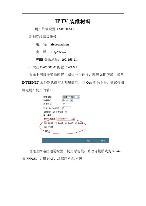
IPTV装维材料一、用户终端配置(MODEM)定制终端超级帐号:用户名:telecomadmin密码:nE7jA%5mWEB登录地址:192.168.1.11、大亚DW5005-G配置(W AN)普通上网桥接通道配置:新建一个连接,配置如图所示;虽然INTERNET服务默认绑定无归属端口,但Qos效果不好,建议按图绑定用户使用的端口普通上网路由通道配置:使用原连接,修改连接模式为Route,选PPPoE,启用NAT,填写用户名/密码IPTV通道配置:新建一个连接,启用vlan功能,统一配置vlan 45;启用802.1p队例优先级,服务类别绑定Other,用户端口绑定LAN2点击:网络→Qos,开启Qos功能点击:获取队列,打开Qos队列配置页面点击:添加,配置Qos队列,保存/应用;队列优先级高低顺序1>2>3>4返回Qos队列配置页面,点击:保存/重启,关闭该页面返回Qos设置页面,点击:添加,打开Qos流配置页面配置Qos流,物理LAN口选择与队列对应的用户端口;点击:确认,增加Qos流返回Qos设置页面,点击:保存/应用所有设置完成后,点击:管理→设备管理→保存/重启;完成重启后配置生效,IPTV通道上行优先转发。
2、大亚DB120-WG配置(ADSL接入)普通上网桥接通道配置:使用VPI为0、VCI为32的连接,保持默认配置即可;INTERNET服务默认绑定无归属端口,规范配置选取非IPTV端口普通上网路由通道配置:使用VPI为0、VCI为32的连接,修改连接模式为Route,选PPPoE,启用NAT,填写用户名/密码IPTV通道配置:新建一个连接,VPI\VCI设8\45,启用802.1p 队例优先级,服务类别绑定Other,端口绑定LAN2点击:网络→Qos,开启Qos功能点击:获取队列,打开Qos队列配置页面点击:添加,配置Qos队列,保存/应用;队列优先级高低顺序1>2>3>4返回Qos队列配置页面,点击:保存/重启,关闭该页面返回Qos设置页面,点击:添加,打开Qos流配置页面配置Qos流,物理LAN口选择与队列对应的用户端口;点击:确认,增加Qos流返回Qos设置页面,点击:保存/应用所有设置完成后,点击:管理→设备管理→保存/重启;完成重启后配置生效,IPTV通道上行优先转发。
调制解调器的安装与配置
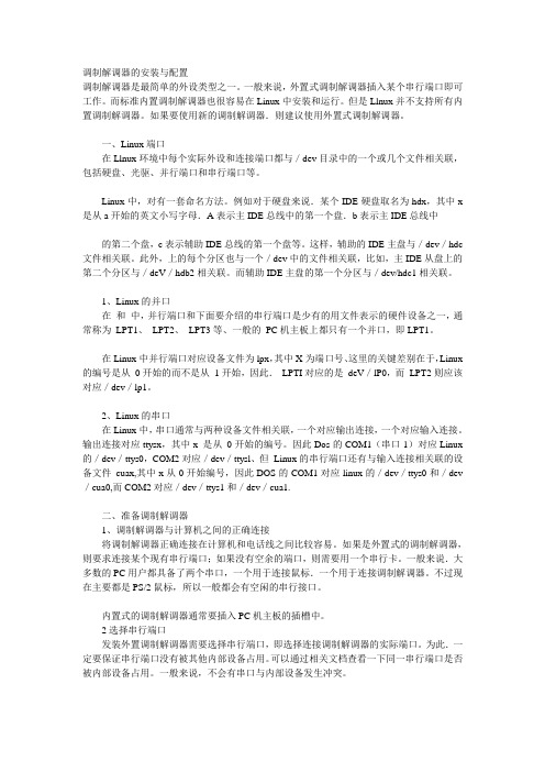
调制解调器的安装与配置调制解调器是最简单的外设类型之一。
一般来说,外置式调制解调器插入某个串行端口即可工作。
而标准内置调制解调器也很容易在Linux中安装和运行。
但是Llnux并不支持所有内置调制解调器。
如果要使用新的调制解调器.则建议使用外置式调制解调器。
一、Linux端口在Llnux环境中每个实际外设和连接端口都与/dev目录中的一个或几个文件相关联,包括硬盘、光驱、并行端口和串行端口等。
Linux中,对有一套命名方法。
例如对于硬盘来说.某个IDE硬盘取名为hdx,其中x 是从a开始的英文小写字母.A表示主IDE总线中的第一个盘.b表示主IDE总线中的第二个盘,c表示辅助IDE总线的第一个盘等。
这样,辅助的IDE主盘与/dev/hdc 文件相关联。
此外,上的每个分区也与一个/dev中的文件相关联,比如,主IDE从盘上的第二个分区与/deV/hdb2相关联。
而辅助IDE主盘的第一个分区与/dev/hdc1相关联。
1、Linux的并口在和中,并行端口和下面要介绍的串行端口是少有的用文件表示的硬件设备之一,通常称为LPT1、LPT2、LPT3等、一般的PC机主板上都只有一个并口,即LPT1。
在Linux中并行端口对应设备文件为lpx,其中X为端口号、这里的关键差别在于,Linux 的编号是从0开始的而不是从1开始,因此.LPTI对应的是deV/lP0,而LPT2则应该对应/dev/lp1。
2、Linux的串口在Linux中,串口通常与两种设备文件相关联,一个对应输出连接,一个对应输入连接。
输出连接对应ttysx,其中x 是从0开始的编号。
因此Dos的COM1(串口1)对应Linux 的/dev/ttys0,COM2对应/dev/ttysl、但Linux的串行端口还有与输入连接相关联的设备文件cuax,其中x从0开始编号,因此DOS的COM1对应linux的/dev/ttys0和/dev /cua0,而COM2对应/dev/ttys1和/dev/cua1.二、准备调制解调器1、调制解调器与计算机之间的正确连接将调制解调器正确连接在计算机和电话线之间比较容易。
ESI U168 XT 24-bit USB 音频接口用户手册说明书

Professional 24-bit USB Audio Interface用户手册ESI, 上海怡歌 - Copyright © 2016 - 2017 Chinses Revision 27, Aug 2017base on English Revision 2, May 2017目录1.引言 (4)1.1简介 (4)2.安装 (7)2.1系统建议 (7)2.2硬件安装 (7)2.3驱动软件安装 (7)2.3.1Windows系统下的安装 (7)2.3.2Mac OS X系统下的安装 (9)3.控制台 (10)3.1Latency(延迟)设置 (11)4.技术参数 (11)5.通用信息 (13)341. 引言U168 XT 是适用于Mac 和PC 的USB 2.0高速音频接口,通过提供更好的性能来获得更好的效果,将USB 音频技术带入新的水平。
该设备提供不少于16个输入通道和8个可同时使用的输出通道。
24-bit / 96kHz 解决方案不仅提供平衡的1/4”TRS 线路连接器,前面板还包括4个集成前置放大器的XLR 话筒输入(带+48V 幻象电源),2个可连接电吉他的Hi-Z 乐器输入以及同轴数字S/PDIF 输入和输出,前面板还有两个独立的耳机输出,一个集成的监听混音器。
外部键盘、合成器和声音模块可以通过后面板的MIDI 输入和输出连接。
U168 XT 提供基于EWDM 和DirectWIRE 技术的快速高性能低延迟驱动程序,支持PC 和Mac 的最新WDM 、ASIO 2.0和CoreAudio 技术,可以满足当前所有所有当前标准音频应用程序的专业用途。
所有这一切使外观时尚的U168 XT 音频接口将专业应用的USB 音频提升到一个新的水平。
1.1 简介U168 XT 的前面板具有以下主要功能:1. 话筒和Hi-Z 乐器输入通道1 使用XLR/TRS 多用康宝接口,使用此接口可连接动圈、电容话筒或电吉他。
数字光纤直放站用户手册
GSM900/DCS1800 数字光纤直放站
用户手册
深圳市西瑞克斯通信设备有限公司 Shen Zhen Cylix Technology Communication Equipment
Co.,Ltd.
密级:公开
GSM900/DCS1800 数字光纤直放站用户手册
目录
第一章 系统概述 ...................................................................................................................... 3 1.1 概述 ............................................................................................................................... 3 1.2 基本原理 ....................................................................................................................... 4 1.3 组网方式 ....................................................................................................................... 5 1.4 产品特点 ....................................................................................................................... 7 1.5 技术指标 ....................................................................................................................... 8 1.5.1 主要技术指标 .................................................................................................. 8 1.5.2 机械特性 .......................................................................................................... 9 1.5.3 接口 .................................................................................................................. 9
TPT-D24调制解调器(插板式)使用说明书zxl
TPT-D24调制解调器使用说明书(插板式)一.主要功能与特点1.TPT-D24调制解调器是一种多功能,多用途的调制解调器。
在市话电缆,长途通信电缆或电力载波电路、微波等电路上使用,占用全话路0.3KHZ~3.4KHZ音频带宽或2.4KHZ~3.4KHZ上音频带宽传输数字信号。
通信线路衰耗值最大允许为40db,该装置采用中大规模集成芯片,技术指标先进,可靠性高,抗干扰能力强。
2.通用性强,适应范围广。
传输速率1200bit/s,600bit/s,300bit/s可方便选择,适用于点对点通信和共线点对多点的通信,通对信线路具有低电平自动切拉功能和人工切换功能。
3.装置使用过程中不需进行任何元件参数的调整,性能稳定,维护使用方便。
二.主要技术指标1.调制方式:2FSK制2.传输速率:全话路使用1200bit/s f o=1700HZ 频偏±400HZf o=1700HZ 频偏±500HZ600bit/s f o=1500HZ 频偏±200HZ上音频复用300/600bit/s f o=2880HZ 频偏±200HZf o=3000HZ 频偏±200HZ3.通信方式:四线制全双工。
4.线路特性阻抗:平衡式600Ω。
5.具备Polling(问答式)和CDT(循环式)传输方式和条件。
6.数据接口:RS232/ V23。
7.具备通信线路主备自动切换或人工切换功能,主备信道自动切换时间为7秒。
8.发送电平:最大+2db/600Ω,可调。
9.最低接收电平:-40db/600Ω。
10.告警电平:-43db/600Ω。
11.误码率Pe:当信号噪声比为15db时,Pe≤1×10⁻⁵。
12.码元失真:≤±10%。
三.使用说明(一). 端子定义1.通信线路接线端X2:1 主信道接收23 主信道发送45 备信道接收67 备信道发送82.48线数据口接线端X1:B2:+12VB4:-12VD30:+5VD10B10 0VZ10D4:RTSA A口请求发送线输入Z14:RTSB B口请求发送线输入Z4:CTSA A口发送允许线输出D16:CTSB B口发送允许线输出D2:TxDA A口调制数据信号输入D14:TxDB B口调制数据信号输入D6:CDA A口载波捡出B16:CDB B口载波捡出Z2:RxDA A口解调数据输出B14:RxDB B口解调数据输出Z6:CpA A口时钟输出线Z16:CpB B口时钟输出线(二). 开关设置定义1.K1 拨动开关K1-1 ON:长发载波状态(常规)OFF:断续发送载波状态K1-2 OFF:全话路使用ON:上音频复用K1-3 OFF:传输速率设置为300b/s和600b/sON:传输速率设置为1200b/sK1-4 OFF:上音频复用时,信号中心频率为3000HZON:上音频复用时,信号中心频率为2880HZK1-5 OFF:CDT方式,需要装置的CPA或CPB时钟为数据采样时钟时,K1-5 在OFF位。
调制解调器说明书
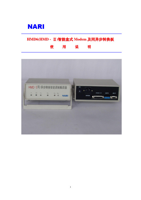
NARIH M D6(H M D-Ⅱ)智能盒式M o d e m及同异步转换板使用说明国家电力公司电力自动化研究院南京鼎瑞华自动化设备有限公司二〇〇〇年七月目录一、概述 3二、功能 3三、参数3四、接口信号定义 3五、指示灯定义 4六、运行状态设置 4HMD6(HMD—Ⅱ)智能盒式Modem及同异步转换板使用说明一、概述HMD6(HMD -Ⅱ)智能盒式Modem是一种音频设备,采用FSK调制方式,可以和电力线载波机配合使用,全双工传送一路或两路中、低速远动信息,并可根椐使用场合选用CDT或polling通信方式。
HMD6(HMD -Ⅱ)智能Modem由单片机及其外围元件组成,采用软硬件结合的方式设计,具有电路简单,运行稳定,抗干扰强,使用方便等优点。
HMD6(HMD -Ⅱ)为盒式结构,自带电源,灵活方便地使用于RS232C特性的通信场合。
二、功能1.异步/同步间转换:(异步接收主机信号,同步转发至RTU等)以EIA-RS232C方式接收异步通信信号,用FSK调制方式同步(或异步)发送。
2.同步/异步间转换:(同步接收RTU等,异步转发至主机)以同步方式接收FSK调制信号,解调后用EIA-RS232C异步方式发送3.当接收载波模拟信号时,采用变压器隔离。
4.不需同/异步转换时,为直通信号,即对主机(或RTU)发来的信号直接进行调制(或解调),此时双方传送的信号可能是异步(也可能是同步)方式。
三、参数1.信号速率:通道部分:300-1200b/s(同/异步) 转换部分:300-9600b/s(异步)2.允许频率偏差:发送端允许偏差:≤10Hz接收端允许偏差:≤16Hz 3.发送电平:0~-18dB可变4.接收电平:0~-30dB 5.灵敏度:>-40dB 6.数据接口特性:EIA-RS232C 7.电源:+5V、±12V、±10% 8.电流:≤200mA四、 I/O端子定义(采用DB25孔和DB9孔插座):1.电源部分:内部供电(+5V、±12V)2.主机部分:DB25.(1) 机壳地、DB25.(7)信号地GND DB25.(2) TXD由主机发送数据至通道板转换接口DB25.(13) RTS由主机发送信号至通道板转换接口DB25.(3) RXD由通道板转换接口发送数据至主机DB25.(18) RXC由通道板转换接口发送信号至主机DB25.(12) CTS由通道板转换接口发送信号至主机DB25.(6) CD由通道板转换接口发送信号至主机3.通道部分:DB25. (9) FSKOUT1DB25.(10) FSKOUT2 DB25.(11) FSKIN1 DB25.(17) FSKIN2 DB25.(22) FSKOUT3 DB25.(25) FSKOUT4 或 DB9.(1) FSKOUT1 DB9.(9) FSKOUT2 DB9.(6) FSKIN1 DB9.(5) FSKIN2 DB9.(4) FSKOUT3 DB9.(8) FSKOUT4五、指示灯定义(参见面板结构)P ——亮:表示电源供电正常CD——亮:表示通道接收信息不正常或关载频信号异常T XD——闪亮:表示通道板发送信息R XD——闪亮:表示通道板接收信息S YN——常亮:表示通道板进行同/异步转R UN——闪亮:表示通道板运行正常六、状态设置:(参见图表Fig6)其中:S1 S2都为10位状态开关S1开关在背板处的印制板外侧(兰色)S2开关在背板处的印制板里侧(红色)1.S1:调制/解调部分的参数设置1~2位:(RL0,RL1)接收电平的设置。
24G15N 用户手册说明书

24G15N安全 (1)标志惯例 (1)电源 (2)安装 (3)清洁 (4)其它 (5)设置 (6)物品清单 (6)安装支架和底座 (7)调整视角 (8)连接显示器 (9)Adaptive-Sync功能 (10)HDR (11)调节显示器 (12)热键 (12)OSD设定 (13)Luminance(明亮度) (14)Color Setup(颜色设置) (15)Picture Boost(窗口增亮) (16)OSD Setup(OSD设置) (17)Game Setting(游戏设置) (18)Extra(其它) (19)Exit(退出) (20)LED指示灯 (21)故障排除 (22)规格 (23)主要规格 (23)预设显示模式 (24)引脚分配 (25)即插即用版权说明.................................................................................................................................................................. ..................................................................................................................................................................2626安全标志惯例以下小节描述此文档中使用的标志惯例。
注释、注意和警告在本指南中,文本块可能带有图标并且以粗体或斜体打印。
这些文本块是注释、注意和警告,如下所示:注释:注意事项指示帮助你更好地使用你的计算机系统的重要信息。
注意:“注意”表示潜在的硬件损坏或数据丢失,并告诉您如何避免出现问题。
tm-dmx-rx24-说明书

THEATRELIGHT解码器系列TL DMX RX24解码器使用说明书THEATRELIGHT-ASIA中山新泰立灯光有限公司目录1、概述 (3)2、TL DMX RX24 解码器的规格 (3)3、装箱清单 (3)4、使用条件 (3)5、使用注意事项 (4)6、面板各部分功能以及输入和输出导线的连接 (4)6.1、面板示意图 (4)6.2 电源输入导线的连接 (5)6.3 DMX 512信号插座 (5)6.4 模拟信号输出插座——DB25公针输出插座插口 (6)6.5 DMX地址码 (6)6.6 DMX信号指示灯和POWER电源指示灯 (7)6.7 输出电压选择侧拨开关和微调电位器 (7)TL DMX RX24解码器使用说明书1.概述TL DMX RX24是新西兰THEATRELIGHT公司设计的DMX512数字解码器,可将DMX512数字信号中所包含的24路数字信号转变为24路+5V、+6V、+7.5V或+10V的直流电压输出;而且解码器还带有微调电位器,通过调整微调电位器,可将输出电压在如上电压值的基础上适当进行调整,调整的范围是-1%到+20%。
通过通过添加TL DMX RX24解码器,DMX512信号可控制许多模拟设备,如模拟硅箱等设备。
2. TL DMX RX24 解码器的规格型号型号简写输出路数外型尺寸(mm)重量(kg)安装方式TL DMX RX24 RX24 24 58H×360W×55D 1.5 壁挂式3. 装箱清单1) TL DMX RX24解码器一台;2) 使用说明书一份;3) 合格证一张;4) 保修卡一张。
4. 使用条件1) 输入电源采用单相三线制(单相火线、零线和地线各一根),相电压为220~240VAC,频率为45~65HZ(如果需要在110VAC的条件下使用,需要在内部修改电路,请联系本公司)2) 输入信号:USITT DMX512 (1990)标准数字信号。
ProSafe Plus 24-Port Gigabit Switch 产品说明书
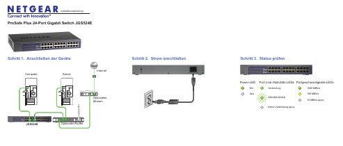
ProSafe Plus 24-Port Gigabit Switch JGS524EEinAusPower-LEDInstallationsanleitungAktivität (blinkt)Keine Verbindung (aus)VerbindungPort Link-/Aktivitäts-LEDs 1000 MBit/s100 MBit/sPortgeschwindigkeits-LEDs10 MBit/s (aus)Optionales ModemJGS524EOptionaler RouterComputerServerInternetSchritt 1. Anschließen der GeräteSchritt 2. Strom anschließen Schritt 3. Status prüfenSeptember 2012Dieses Symbol wurde in Übereinstimmung mit der EU-Richtlinie 2002/96/EG zu Elektro- undElektronik-Altgeräten (WEEE-Richtlinie) hier angebracht. Die Entsorgung dieses Produkts innerhalb der Europäischen Union sollte in Übereinstimmung mit den in Ihrem Land zur Implementierung der WEEE-Richtlinie geltenden Gesetzen gehandhabt werden.NETGEAR, das NETGEAR Logo und Connect with Innovation sind Marken und/oder eingetragene Marken von NETGEAR, Inc. und/oder seiner Tochtergesellschaften in den USA und/oder anderen Ländern. Informationen können ohne vorherige Ankündigung geändert werden. Andere Marken- und Produktnamen sind eingetragene Marken oder Marken der jeweiligen Inhaber. © NETGEAR, Inc. Alle Rechte vorbehalten.In den Staaten der EU und in der Schweiz nicht für die Verwendung im Freien zugelassen.Die vollständige EU-Konformitätserklärung finden Sie unter /app/answers/detail/a_id/11621/.Hinweis: Zur Verbesserung des internen Designs, des Betriebs und/oder der Zuverlässigkeit behält NETGEAR sich das Recht vor, die in diesem Dokument beschriebenen Produkte ohne vorherige Ankündigung zu ändern. NETGEAR lehnt im Zusammenhang mit dem Einsatz oder der Anwendung der hier beschriebenen Produkte oder Schaltpläne jegliche Haftung ab.Einrichten desSwitch-KonfigurationsprogrammsPlus-Switches sind plug-and-play-fähig. Sie können ein Konfigurationsprogramm installieren, um zusätzliche Optionen auszuwählen, mit denen Sie den Switchverwalten und für Ihr Netzwerk anpassen können. Dieses Dienstprogramm befindet sich auf der Begleit-CD, die Sie zusammen mit dem Switch erhalten haben.Hinweis:Das Konfigurationsprogramm ist auf dem Computer installiert und wird nur auf Windows unterstützt.Installieren Sie das Konfigurationsprogramm:1. Legen Sie die Begleit-CD in einen Computer ein, der an den Switchangeschlossen ist.2. Klicken Sie auf Install ProSafe Plus Utility , und folgen Sie den Anweisungen,um das Programm zu installieren.Das Switch-Konfigurationsprogramm wird in das Programmverzeichnis des Computers installiert, und auf dem Desktop wird ein ProSafe Plus Utility-Symbol erstellt.Konfigurieren Sie den Switch:1. Klicken Sie doppelt auf das ProSafe Plus Utility -Symbol.Plus-Switches, die das Gerät im lokalen Netzwerk ermitteln kann, werden auf der Konfigurations-Startseite angezeigt.2.Wählen Sie den Switch aus, der konfiguriert werden soll.Sie müssen nun das Passwort für den Switch eingeben. 3.Geben Sie dieses in das Passwort-Feld ein.Das Standard-Passwort ist "password".4.Konfigurieren Sie den Switch nun mit dem Programm.Eine Beschreibung der Funktionen finden Sie im Benutzerhandbuch zum Thema Konfigurationsprogramm für ProSafe Plus Switch. DasBenutzerhandbuch befindet sich auf der Begleit-CD, aber Sie erreichen es auch über die Links im Hilfe-Bereich des Programms.Technische DatenSpezifikation BeschreibungNetzwerkschnittstelleRJ-45-Anschluss für 10BASE-T, 100BASE-TX oder 1000BASE-TNetzwerkkabel Kategorie 5e (Kat 5e), besser: Netzwerkkabel Port 24Power 100-240 VAC, 50-60 Hz, 0,9 A max.Stromverbrauch Max. 13,5 W Gewicht 1,73 kg (3,79 lbs)Abmessungen (B x T x H)330 mm x 173 mm x 43 mm 13 in. x 6,8 in. x 1,7 in.Betriebstemperatur 0–40° C (32–104° F)Luftfeuchtigkeit 10-90 % relative Luftfeuchtigkeit, nicht kondensierendElektromagnetische Verträglichkeit CE-Klasse A, FCC Klasse A, VCCI Klasse A, C-Tick Klasse A, CCCSicherheitszertifikateCE-Zeichen, Commercial UL-gelistet (UL 60950-1), CB, CCCTechnischer SupportNach der Installation des Geräts können Sie das Produkt unterhttps:// registrieren. Die Seriennummer finden Sie auf dem Etikett Ihres Produkts.Die Registrierung ist Voraussetzung für die Nutzung des telefonischen NETGEAR Supports. NETGEAR empfiehlt, das Gerät über die NETGEAR Webseite zu registrieren. Produkt-Updates und Support im Internet erhalten Sie unter .。
有线电视调制解调器路由器快速入门指南说明书
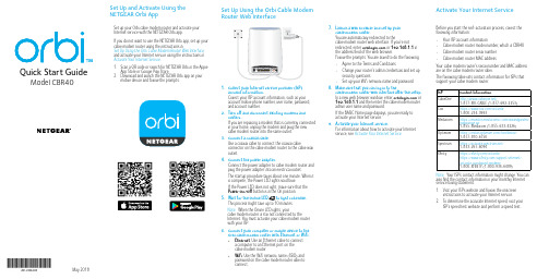
Quick Start GuideModel CBR401. Collect your Internet service provider (ISP)account information.Collect your ISP account information, such as youraccount mobile phone number, user name, password,and account number.2. Turn off and disconnect existing modems androuters.If you are replacing a modem that is currently connectedin your home, unplug the modem and plug the newcable modem router into the same outlet.3. Connect a coaxial cable.Use a coaxial cable to connect the coaxial cableconnector on the cable modem router to the cable walloutlet.4. Connect the power adapter.Connect the power adapter to cable modem router andplug the power adapter into an electrical outlet.The startup procedure takes about one minute. When itis complete, the Power LED lights solid blue.If the Power LED does not light, make sure that thePower On/Off button is in the On position.5. Wait for the Online LED to light solid blue.This process might take up to 10 minutes.Note: When the Online LED lights, yourcable modem router is still not connected to theInternet. You must activate your cable modem routerwith your ISP.6. Connect your computer or mobile device to theOrbi cable modem router with Ethernet or WiFi:• Ethernet. Use an Ethernet cable to connecta computer to an Ethernet port on thecable modem router.• WiFi. Use the WiFi network name (SSID) andpassword on the cable modem router label toconnect.Activate Your Internet ServiceBefore you start the self-activation process, collect thefollowing information:• Your ISP account information• Cable modem router model number, which is CBR40• Cable modem router serial number• Cable modem router MAC addressYour cable modem router’s serial number and MAC addressare on the cable modem router label.The following table lists contact information for ISPs thatsupport your cable modem router.ISP Contact InformationCableOne /1-877-MY-CABLE (1-877-692-2253)Cox https:///activate1-800-234-3993Mediacom https:///walledgarden/page/login.jsp1-855-Mediacom (1-855-633-4226)Optimum https:///JointInstall/1-877-810-6750Spectrum https:///1-833-267-6094Xfinity https:///activatehttps:///support/internet/activate-purchased-modem/1-800-XFINITY (1-800-934-6489)Note: Your ISP’s contact information might change. You canalso find the contact information in your monthly Internetservice billing statement.1. Visit your ISP’s website and follow the onscreeninstructions to activate your Internet service.2. To determine the accurate Internet speed, visit yourISP’s speed test website and perform a speed test.May 20187. Launch a web browser and set up yourcable modem router.You are automatically redirected to thecable modem router web interface. If you’re notredirected, enter or 192.168.1.1 inthe address field of the web browser.Follow the prompts. You are asked to do the following:• Agree to the Terms and Conditions• Change your router’s admin credentials and set upsecurity questions• Set up your WiFi network name and password8. Make sure that you can log in to thecable modem router web interface after the setup.In a new web browser window, enter or192.168.1.1 and then enter the cable modem routeradmin user name and password.If the BASIC Home page displays, you are ready toactivate your Internet service.9. Activate your Internet service.For information about how to activate your Internetservice, see Activate Your Internet Service.Set Up and Activate Using theNETGEAR Orbi AppSet up your Orbi cable modem router and activate yourInternet service with the NETGEAR Orbi app.If you do not want to use the NETGEAR Orbi app, set up yourcable modem router using the instructions inSet Up Using the Orbi Cable Modem Router Web Interface,and activate your Internet service using the instructions inActivate Your Internet Service.1. Scan a QR code or search for NETGEAR Orbi in the AppleApp Store or Google Play Store.2. Download and launch the NETGEAR Orbi app on yourmobile device and follow the prompts.Set Up Using the Orbi Cable ModemRouter Web InterfaceSupportThank you for purchasing this NETGEAR product. You can visit /support to register your product, get help, access the latest downloads and user manuals, and join our community. We recommend that you use only official NETGEAR support resources.Customer-owned cable modem routers might not be compatible with certain Internet service providers (ISPs). Check with your ISP to confirm that this NETGEAR cable modem router is allowed on your ISP’s network.If you are experiencing trouble installing your NETGEAR product, contact NETGEAR at 1-866-874-8924.For regulatory compliance information, visit /about/regulatory/.See the regulatory compliance document before connecting the power supply.© NETGEAR, Inc., NETGEAR and the NETGEAR Logo are trademarks of NETGEAR, Inc. Any non-NETGEAR trademarks are used for reference purposes only.NETGEAR INTL LTDBuilding 3, University Technology CentreCurraheen Road, Cork, IrelandNETGEAR, Inc.350 East Plumeria Drive San Jose, CA 95134, USAOrbi Cable Modem Router(Model CBR40)Ethernet cablePackage ContentsPower adapterRing LED (not shown in image)Power LED Downstream LED Upstream LED Online LEDSync button (also used for WPS connection)Ethernet ports Coaxial cable connector Reset button DC power connector Power On/Off buttonOrbi Cable Modem Router Overview2134567811Orbi Cable Modem Router LEDs16109。
RB-24模式说明书
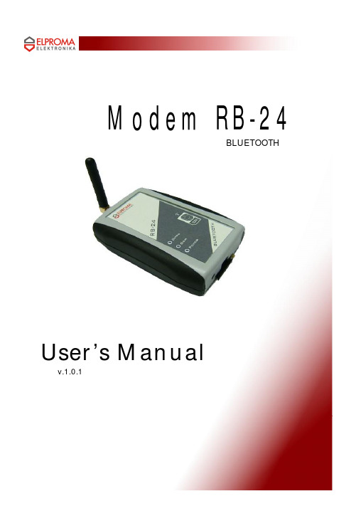
Modem RB-24BLUETOOTH User’s Manualv.1.0.1SWITCH ON SAFELY Do not switch the modem on when wireless devices useis prohibited, or when it may cause interference or danger.ATTENTIONINTERFERENCEAll wireless modems may be susceptible to interference,which could affect performance.SWITCH OFF IN HOSPITALS Follow any restrictions. Switch the modem off nearmedical equipment.QUALIFIED SERVICEOnly qualified personnel may install or repair this product.WATER-RESISTANCEYour modem is not water-resistant. Keep it dry.USE SENSIBLY Use only in the normal position as explained in the product documentation. Don't touch the antenna unnecessarily.WELCOMEThis document will provide you with the instructions how to install and use modem “RB 24” and its software.RB24terminal is powered by Motorola’s G24.It features multiple configurations, including USB, Bluetooth and RS232. RB24 RS232 is a small terminal-modem powered by Motorola G24 embedded engine. RS232 version is a EDGE/GPRS/GSM dedicated for users seeking for easy and mobile internet access. It enables users to use all services provided by GSM operators. Internet/APN Access (EDGE/GPRS), CSD, SMS or FAX just to mention basic capabilities.Additionally it can be used as a mobile phone for voice communication. Perfect when traveling, no need for any external power supply or batteries. Ready PC software for WindowsXP and Linux OS. RS232 version is typical terminal/driver. Small sized easy to install is a perfect solution for any GSM/GPRS telemetry system.1. PACKAGE CONTENTSModem RB-24 is supplied to clients in carton with all1 contents, which are needed for connection to PC and normalwork:1) carton;2) modem RB24 BLUETOOTH;3) “USB A mini USB B” connecting cable;4) external GSM antenna;5) headset6) AC power supply with mini-USB plug output7) CD with User’s Guide and drivers.If any of the components is missing please contact your local distributor.2. T echnical information2.1. Modem features.GSM / GPRS / EDGE / CSD / SMS / FAX modemGSM 850 / 900 / 1800 / 1900 / E-GSMFunctions:EDGE (Mult-slot class 10, max BR downlink 236,8 Kb/s)GPRS (Multi-slot class 10, max BR downlink 85,6 Kb/s) 2FAX (3 group 1 class) 9600bit/sSMS (AT commands ETSI 07.05 & 07.07, PDU & Text)CSD (Max BR 14,4 Kb/s)Bluetooth® 2.0+EDR (up to 3Mbit/s)public device name: RB24default PIN code: 0000class of device (CoD): phone (0x520204)supported profiles:Serial Port Protocol (SPP)Dial-Up Networking (DUN)radio class 2 (range up to 10m)2.2. Electrical and operating specifications.Power supply: 5V DCPower consumption: max 950mASIM Card: 3V DC2.3. Weight and dimensions.Weight100gLength95mmWidth65mmDepth30mm22.4. Panels.A) front panel: headset and mini-USB connectors, SIM-holderB) top panel: 3 LEDs state indicator: POWER ,GSM (data),GPRSC) back panel: antenna SMA connector23. Hardware setupunpack and prepare components from the device boxprepare a SIM cardpress a yellow button of the SIM-holder on the front panelextract the trayput the SIM cardinsert the set3screw the antenna to the SMA connectoron the backpanellif it is necessary plug-in the USB connectorto your computer (a host)plug-in the mini-USB connector ofUSB cable or AC adaptor to thesocket 34. Bluetooth instalationThe device has to own Bluetooth radioBluetooth stack which supports SPP and/orDUN Bluetooth profilesproper distance between the devices (range upto about 10 meters, it depends on environment parameters for radio frequencies, the devices class of power and sensitivity)To connect with the RB24 BLUETOOTH your device (PC / laptop, palmtop, etc.) you need the following things:1. Windows-like OS • native Microsoft ® Windows XP ®SP2 (Service Pack 2)– Generic Bluetooth Radio driver • native Microsoft ® Windows Vista®• IVT BlueSoleil ®()• Widcomm ®(by Broadcom, )2. Unix-like OS (Linux)• BlueZ ()• Affix (developed by Nokia ®, )• OpenBT (/projects/openbt)As Bluetooth radio for computer you can use a cheap USB Bluetooth Dongle. Most of them is based on CSR ® BlueCore ®chip with HCI (Host Command Interface) support . The stack and drivers should be attached to the dongle.If you have not got a Bluetooth stack it is even possible usageone of native stacks for Operating Systems like Microsoft ®Windows or Linux / BSD . Below it is listed several well knownBluetooth stacks for PC: .4General steps you have to do in order to make the firstconnection with the RB24:• call inquiry – scan Bluetooth enabled devices around• select a device named RB24 (phone class)• pair with RB24 for keys exchange, necessary to enter the PIN code (0000)• for some stacks check supported services (SDP) and select SPP or DUN profile• the stack should make a virtual serial port for SPP(UUID: 0x1101, RFCOMM, channel 1)• for DUN (UUID: 0x1103, RFCOMM) a stack can displayInternet connection dialog (Dial-Up)• now you can open the virtual serial port (eg. COM37,/dev/rfcomm1) in a terminal (HyperTerminal, minicom,tip, etc.) or other software for the modemGeneral steps you have to do every next time:4• for some stacks define RFCOMM channel (eg. BlueZ)• open the virtual serial port...5. LimitationsNOTEOnly the first client (SPP or DUN) will able to transfer data from/to modem. If you want to change the active profile you need to disconnect the previous connection .IMPORTANTThe RB24 Bluetooth version requires not to use AT+IPR=... command. If you change the serial port baud rate a Bluetooth connection may result in data fault. In order to undo a mistake you have to plug the device to computer by the USB cable. Afterwardsyou should open a serial port terminal (USB modem represented bya virtual COM port) and send “AT+IPR=230400” command. The230 400 baud rate is an internal speed of data transfer betweenthe GSM modem and the Bluetooth part .Another possibility is to run the GPRS Control software forRB24 connected to the USB, close the connection, un-plug andplug-in the modem to mini-USB again .56. Bluetooth connection guideWindows XP SP2Click double on the Bluetooth iconPress the “Add” button6Select the RB24 and press the “Next” buttonTick the checkbox and press the “Next” button6You should get COM ports number, interesting foryou is the outgoing port COM, press the Finish buttonSelect “Use access code from documentation “,enter PIN code and press the “Next”button6The final effect: paired the devicesNow you can open eg. HyperTerminal with virtual serial port COM228 (the outgoing port) – next time youwill need only this stepou should get COM ports6 number, interesting for you is the outgoing port COM,press the Finish button.Windows XP, WIDCOMM stackClick double on the WIDCOMM Bluetooth iconnalSelect “View devices in range”6Wait until inquiry finishes and click double on “RB246Wait until inquiry finishes and click double on “RB24You should notice something like belowWait until inquiry finishes and click double on “RB246Now you can use the virtual port (eg. COM11) where you need(eg.the HyperTerminal).The final result for the SPP connection6If you want to connect to Internet via PPP(Point-to-Point Protocol) click double.on “Dial-Up Networking” serviceYou should notice something like below6The standard dialog for the connection will be displayed. For GPRS/EDGE connection enter one of the following numbers: . *99# (default APN) . *99***1# (APN1) . *99***2# (APN2) . *99***3# (APN3) .Enter the PIN code for the devices pairing if it isnecessary6Windows XP, IVT BlueSoleil stack Click double on the BlueSoleil Bluetooth iconnClick on a star like the Sun in the center of theBlueSoleil windows.6Please wait for the inquiryClick double on the new mobile phone device (RB24)6Now the RB24 is paired with the BlueSoleil stackand its services are discovered.Enter the PIN code and press the “OK” button 6If you want to connect to Internet via PPP(Point-to-Point Protocol) click double.on “Dial-Up Networking” serviceThe result: is the virtual serial port and modem(eg. COM251), click the “Yes” button6The standard dialog for the connection will be displayed. For GPRS/EDGE connection enter one ofthe following numbers:.*99# (default APN).*99***1# (APN1) .*99***2# (APN2) .*99***3# (APN3) .6The result: is the virtual serial port (eg. COM444),click the “Yes” buttonIf you want to create a virtual COM port click on“Serial Port”service 6On the successful finish you should see somethingbelowlike6• Ciheck your HCI Bluetooth Dongle$hcitool dev Devices:hci0 00:13:EF:F0:C3:54• Find the RB24$hcitool scan name Scanning ...00:A0:96:07:41:2A Bluetooth Display00:07:80:82:F5:75 RB24• Discover services$sdptool search 0x1002Class 0x1002Inquiring ...Searching for 0x1002 on 00:07:80:82:F5:75 ...Service Name: Bluetooth Serial Port Service RecHandle: 0x10000Service Class ID List:"Error: This is UUID-128" (0x00001101-0000-1000-8000-00805f9b34fb)Protocol Descriptor List:"L2CAP" (0x0100)"RFCOMM" (0x0003)Channel: 1Language Base Attr List:code_ISO639: 0x656eencoding: 0x6abase_offset: 0x100Service Name: Dial-Up NetworkingService RecHandle: 0x10001Service Class ID List:"Error: This is UUID-128" (0x00001103-0000-1000-8000-00805f9b34fb)Protocol Descriptor List:"L2CAP" (0x0100)"RFCOMM" (0x0003)Channel: 2Language Base Attr List:code_ISO639: 0x656eencoding: 0x6abase_offset: 0x100Searching for 0x1002 on 00:A0:96:07:41:2A ...• Pair the devices: PIN checking and keys exchanging (needed only the first time)$sudo hcitool cc 00:07:80:82:F5:75$hcitool con Linux, BlueZ stack6Connections:< ACL 00:07:80:82:F5:75 handle 42 state 1 lm MASTER• SPP connection$rfcomm connect /dev/rfcomm0 00:07:80:82:F5:75 1Connected /dev/rfcomm0 to 00:07:80:82:F5:75 on channel 1Press CTRL-C for hangup• open your terminal, for example$gtkterm -p /dev/rfcomm0• DUN connection (you can also use SPP instead of DUN, the result will be the same)$rfcomm connect /dev/rfcomm1 00:07:80:82:F5:75 2Connected /dev/rfcomm1 to 00:07:80:82:F5:75 on channel 2Press CTRL-C for hangup6。
新ADSL使用手册

QXCOMMADSLMODEM 使用手册第一章简介ADSLMODEM简介ADSL技术是一项将宽带服务送到家庭和小型公司的新的运转平台。
ADSL是AsymmetricDigitalSubscriberLoop(非对称数字用户回路)的缩写,它的特色是能在现有的铜双绞一般电话线上供给高达8Mb/s的高速下载速率和1Mb/s的上行速率,而其传输距离为3km到5km。
其优势在于不需要从头布线,它充足利用现有的电话线网络,只需在线路两头加装ADSL设施即可为用户供给高速高带宽的接入服务。
ADSL能够支持宽泛的宽带应用服务,比如高速Internet接见,telecommuting电视会议,虚构私有网络以及流格式多媒体应用。
ADSLMODEM与计算机的连结经过网卡来达成。
当您身旁的电话线连上该ADSLMODEM时,在这段电话线上便产生了三个信息通道:一个速率最高可达8160Kbps的下行通道,用于用户下载信息;一个速率为可达896Kbps的上行通道;一个一般的4K电话服务通道(注:使用一般电话服务需要配置一台电话分别器);且这三个通道能够同时工作。
这样,你就能够在下载文件的同时上网冲1浪,而且经过电话给您的朋友聊天。
因为上网与打电话是分别的,所以您上网是不占用电话信号,自然上网就只用网费而没有电话费。
分别器简介与传统的MODEM对比,因为采纳了高频通道,所以与电话同时使用的状况下一定使用分别器。
ADSL技术中的分别器分别器由低通滤波器和高通滤波器构成的。
它接在申请了ADSL业务的一般的电话线的用户端,这样就能分离在4K以下的一般电话信号和ADSL需要的高频信号。
特色和技术指标技术原理ADSL接入技术最大的利处是不需要架设专用网络,它能利用此刻世界上散布最广的电话铜线作为传输介质,并能在一对铜质双绞线(电话线)上获得三个信息通道:一个为标准电话服务的通道、一个速率为的中速上行通道、一个速率为1MBPS-8MBPS的高速下行2通道,而且这三个通道能够同时工作。
戴尔电脑ADSL调制解调器用户指南说明书
NOTEline conditioner, and line splitter connection instructions, as well as contact information for your ADSL Internet service provider.restrictions and disclaimers.NOTE:2. The Warning screen appears. Click Yes.3. The Uninstall Finished screen appears. Click3. Click Finish.4. The System Setting Change screen appears. Click Yes to restart your computer.You successfully reinstalled the ADSL modem driver.See Connecting to the Internet for connection instructions.NOTEreceived with your computer.icon on you desktop.screen appears. Type your FastAccessNOTEThe Connecting To My Connection screen appears.The Connection Established screen appears.4. You are connected to the Internet. Click Close.The ADSL modem diagnostic icon appears on the taskbar.ADSL Modem Diagnostic Icon Color CodesThe status of your Internet connection can be determined by checking the icon color codes:NOTE 1. Right-click the ADSL modem diagnostic iconand then click Color CodeRed, RedBlack, Yellow Black, Black Black, Green Green, Black Green, GreenColor/Location SignalDescriptionYellow Top On TX or RX Off no data ATM data transmission Green Top Fast flash Slow flash Modem Connecting Modem ConnectedThe ADSL Diagnostic Tool screen appears.2. Click the Diagnostic tab and then click Run Diagnostics.3. A Warning Message screen appears.l Click Yes to run the diagnostics.l Click No to exit the diagnostics.Viewing Driver Version Information1. Right-click the ADSL modem diagnostic icon and then click Open.2. Click the Diagnostic tab and then click the Product Information.Jumper-Pin ConfigurationDell configures your ADSL modem in accordance with your ADSL Internet service provider requirements. However, in the event a change becomes necessary, contact your ADSL Internet service provider before changing the jumper-pin setting.The ADSL modem is configured to use Line 1 (pins 3 and 4).Color CodeRed, RedBlack, YellowBlack, BlackBlack, GreenGreen, BlackGreen, Green。
用 户 手 册(V10)

公司产品主要有 10Mbps 高速电力调制解调器、高速电力路由器、高速电力桥集器; 50Mbps 高速电力调制解调器、高速电力桥集器;85Mbps 高速电力调制解调器、高速电力桥 集器;224Mbps 高速电力调制解调器、高速电力桥集器;家庭自动化系统、网络抄表系统等 系列产品。
亿力网络拥有一支高素质的技术和管理专业队伍,现有职工中大专以上学历的员工占职 工总数的 70%以上。
包装清单
安装使用前请检查包装盒中的物品,应包括以下物件:
一台 FPM-224M 高速电力调制解调器主机 一条直连网线 一条直连双头三芯电源线 一本用户手册 一张产品保修卡 一张产品合格证
注意:拆包后如有物件不全或者损坏,请及时与福建省亿力电力网络信息设备有限公司或当 地供应商联系,以便更换。
亿力网络的经营方针为致力于配合国家电力信息产业发展的战略规划,专业提供高质量 的工业和民用电力线网络通信设备,以努力满足社会网络信息化不断发展的要求。
产品简介
感谢您使用亿力网络公司的高速电力调制解调器及其它产品。 FPM-224M 高速电力调制解调器是本公司推出的计算机网络应用产品,可通过电力线在 224Mbps 通信速率上连接宽带网络。“电线上网”是一种全新的“宽带”上网方式,只用一 台电脑、一个高速电力调制解调器,利用任何一个普通的 220V 电源插座,不用布建任何网 络线路,也不需要占用电话线路,点击浏览器就可以上网遨游了。上网速度可与一般的“宽 带”网络相媲美。使得用户享受了宽带的高速便捷,又免去了破坏环境,维护困难的苦恼。 可广泛应用于个人用户、小型办公司系统、校园网络、社区网络、酒店宾馆等。 本公司应用创新技术自行研制的电力线上网技术,全面解决了电力线通信领域长期存在 的不稳定和不安全问题。设计兼容目前的 Windows98/ME/2000/XP 操作系统,用户只要经过 简单的设置,即能通过电力线上网或组成自己的局域网,在使用的灵活性上更胜一筹。利用 电力线上网,网络资源丰富、施工方便、一线两用、价格低廉等。电力线上网不仅为广计算 机网络用户提供了一个新的选择,而且也必然推动整个宽带服务行业的发展与繁荣。
YMD-24说明书仅供参考

(公司图标)光纤芯程控交换机YMD-24产品说明书(公司图标)宁波市樱铭电子科技有限公司Ningbo Ying Ming Electronic Technology Co., Ltd.目录简介 (1)一、概述 (1)二、主要技术参数 (2)三、安装与调整 (2)四、操作使用与维护 (6)五、其它典型产品说明 (11)六、包装运输和贮存 (13)附录:订货指南 (14)1 概述OASS光纤芯程控交换机YMD-24是用于通讯传输行业的设备。
它能够完成24芯的光缆光纤设备中任意两条纤芯的远程自动交换,OASS光纤芯程控交换机YMD-24设备受远端指令控制,实现接入设备所有光缆中的任意两根纤芯的自动对接,实现了24芯光纤芯设备的自动对接,采用精密机械、通信、计算机技术开发的划时代的纤芯自动交换产品,使光缆通讯设备中任意两条纤芯的转换变得非常简单、方便,环境适应性强。
本公司此项产品实现对光纤资源的远程调配、光通道性能的实时监测。
该产品填补了国内外纤芯交换领域研究的一项空白。
该产品符合中华人民共和国通信行业标准“YD/T585-1999”通信用配电设备标准。
2 主要特性1)纤芯自动切换,极大的改善了原采用人工切换纤芯方式所有的费时、费力的弊端,并可有效避免误操作;2)极大的减轻了维护人员的对光缆线路测量维护工作量,节约大量时间及管理运营成本;3)缩短故障处理时间、提高工作效率,从而最大限度的保证光通讯网络的安全可靠运行4)采用冷扎钢板整体焊接。
前部双开门,可拆卸,上下面开孔,方便电缆进线,在不使用时可封闭,防止异物落入。
表面静电环氧粉末喷塑。
5)配电回路按电流级别任意选定(1A~63A),为通信设备提供可靠的AC380V/220V电源。
6)熔断器和断路器均选用高可靠性的产品,根据用户要求选用。
◆进口名厂光电元件◆独特的接口保护电路◆输出光功率稳定可靠◆全部表面贴装工艺,工业级设计2.1采用一进多出的配电方式,供电分配容量最大可达60kVA。
- 1、下载文档前请自行甄别文档内容的完整性,平台不提供额外的编辑、内容补充、找答案等附加服务。
- 2、"仅部分预览"的文档,不可在线预览部分如存在完整性等问题,可反馈申请退款(可完整预览的文档不适用该条件!)。
- 3、如文档侵犯您的权益,请联系客服反馈,我们会尽快为您处理(人工客服工作时间:9:00-18:30)。
TPT-D24调制解调器使用说明书
(插板式)
一.主要功能与特点
1.TPT-D24调制解调器是一种多功能,多用途的调制解调器。
在市话电缆,长途通信电缆或电力载波电路、微波等电路上使用,占用全话路0.3KHZ~3.4KHZ音频带宽或
2.4KHZ~
3.4KHZ上音频带宽传输数字信号。
通信线路衰耗值最大允许为40db,该装
置采用中大规模集成芯片,技术指标先进,可靠性高,抗干扰能力强。
2.通用性强,适应范围广。
传输速率1200bit/s,600bit/s,300bit/s可方便选择,适用于点对点通信和共线点对多点的通信,通对信线路具有低电平自动切拉功能和人工切换功能。
3.装置使用过程中不需进行任何元件参数的调整,性能稳定,维护使用方便。
二.主要技术指标
1.调制方式:2FSK制
2.传输速率:全话路使用1200bit/s f o=1700HZ 频偏±400HZ
f o=1700HZ 频偏±500HZ
600bit/s f o=1500HZ 频偏±200HZ
上音频复用300/600bit/s f o=2880HZ 频偏±200HZ
f o=3000HZ 频偏±200HZ
3.通信方式:四线制全双工。
4.线路特性阻抗:平衡式600Ω。
5.具备Polling(问答式)和CDT(循环式)传输方式和条件。
6.数据接口:RS232/ V23。
7.具备通信线路主备自动切换或人工切换功能,主备信道自动切换时间为7秒。
8.发送电平:最大+2db/600Ω,可调。
9.最低接收电平:-40db/600Ω。
10.告警电平:-43db/600Ω。
11.误码率Pe:当信号噪声比为15db时,Pe≤1×10⁻⁵。
12.码元失真:≤±10%。
三.使用说明
(一). 端子定义
1.通信线路接线端X2:
1 主信道接收
2
3 主信道发送
4
5 备信道接收
6
7 备信道发送
8
2.48线数据口接线端X1:
B2:+12V
B4:-12V
D30:+5V
D10
B10 0V
Z10
D4:RTSA A口请求发送线输入
Z14:RTSB B口请求发送线输入
Z4:CTSA A口发送允许线输出
D16:CTSB B口发送允许线输出
D2:TxDA A口调制数据信号输入
D14:TxDB B口调制数据信号输入
D6:CDA A口载波捡出
B16:CDB B口载波捡出
Z2:RxDA A口解调数据输出
B14:RxDB B口解调数据输出
Z6:CpA A口时钟输出线
Z16:CpB B口时钟输出线
(二). 开关设置定义
1.K1 拨动开关
K1-1 ON:长发载波状态(常规)
OFF:断续发送载波状态
K1-2 OFF:全话路使用
ON:上音频复用
K1-3 OFF:传输速率设置为300b/s和600b/s
ON:传输速率设置为1200b/s
K1-4 OFF:上音频复用时,信号中心频率为3000HZ
ON:上音频复用时,信号中心频率为2880HZ
K1-5 OFF:CDT方式,需要装置的CPA或CPB时钟为数据采样时钟时,K1-5 在OFF位。
ON:Polling方式,CPA或CPB无效,PS600装置使用时K1-5在ON位。
K1-6 OFF:上音频复用状态
ON:全话路使用
2.K2 拨动开关
K2-1 OFF:数据极性取正TxD,RxD 占全话路使用时1200b/s、600b/s K2-1在OFF位。
ON:数据极性取反TxD,RxD 上音频复用时300b/s、600b/s
K2-1在ON位。
K2-2 OFF:1200HZ时钟断开
ON:1200HZ时钟投入
K2-3 OFF:600HZ时钟断开
ON:600HZ时钟投入
K2-4 OFF:300HZ时钟断开
ON:300HZ时钟投入
K2-5的OFF与K2-6的ON:人工切换,主信道工作,主备灯灭。
K2-5的ON与K2-6的OFF:人工切换,备信道工作,主备灯亮。
K2-5的OFF与K2-6的OFF:主备信道自动切换投入。
主备灯灭时为主信道工
作,主备灯亮时为备信道工作。
(三). 绕线针连接
TZ1: 设定A口或B口工作选择
TZ2:1-2断,3-4连工作在CCITTV23模式,即f o=1700±400HZ。
1-2连,3-4断工作在BELL202模式,即f o=1700±500HZ 。
(四). TPT-D24调制解调器参数特征设置表:
TPT-D24调制解调器使用特征参数设置表
注:
1.K1,K2每位开关“0”表示断开(OFF),“1”表示合上(ON);
2.K1-4占话路使用时为不定状态;
3.K1-5由于PS600装置采用异步工作方式(Polling)K1-5设置为ON位。
4.K2-5,K2-6为主备信道切换设置。
双通道切换还要TZ10连。
5.W3主信道发送电平调整,W4备信道发送电平调整。
在发送电平需要调整时方可进行。
6.W5主信道接收电平调整,W6备信道接收电平调整,使用中均勿调整。
7.各电位器使用时无特殊情况切勿调整。
