Automatic control theory 自动控制原理PPT课件
合集下载
自动控制原理教学ppt

前馈校正
在系统的输入端引入一个前馈环节, 根据输入信号的特性对系统进行补 偿,以提高系统的跟踪精度和抗干 扰能力。
复合校正方法
串联复合校正
将串联超前、串联滞后和串联滞 后-超前等校正方法结合起来, 设计一个复合的串联校正环节, 以实现更复杂的系统性能要求。
反馈复合校正
将局部反馈、全局反馈和前馈等 校正方法结合起来,设计一个复 合的反馈校正环节,以实现更全
自适应控制系统概述
简要介绍自适应控制系统的基本原理、结构和特点,为后续内容 做铺垫。
自适应控制方法
详细介绍自适应控制方法,如模型参考自适应控制、自校正控制等, 及其在自动控制领域中的应用实例。
自适应控制算法
阐述自适应控制算法的实现过程,包括参数估计、控制器设计等关 键技术。
鲁棒控制理论应用
鲁棒控制系统概述
自动控制应用领域
工业领域
自动控制广泛应用于工业领域,如自 动化生产线、工业机器人、智能制造 等。
01
02
航空航天领域
自动控制是航空航天技术的重要组成 部分,如飞行器的自动驾驶仪、导弹 的制导系统等。
03
交通运输领域
自动控制也应用于交通运输领域,如 智能交通系统、自动驾驶汽车等。
其他领域
此外,自动控制还应用于农业、医疗、 环保等领域,如农业自动化、医疗机 器人、环境监测与治理等。
提高系统的稳态精度。
串联滞后-超前校正
03
结合超前和滞后校正的优点,设计一个既有超前又有滞后的校
正环节,以同时改善系统的动态性能和稳态精度。
反馈校正方法
局部反馈校正
在系统的某个局部引入反馈环节, 以改善该局部的性能,而不影响 系统的其他部分。
全局反馈校正
《自动控制原理》PPT课件
4
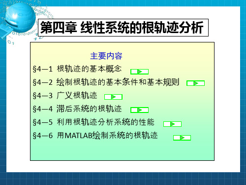
4-1 根轨迹的基本概念
4-1-1 根轨迹
闭环极点随开环根轨迹增益变化的轨迹
目标
系统参数 连续、运动、动态
开环系统中某个参数由0变化到 时,
闭环极点在s平面内画出的轨迹。一 个根形成一条轨迹。
5
例4-1 已知系统如图,试分析 Kc 对系统特征根分布的影响。
R(s)
_ Kc
1
C(s)
s(s+2)
解:开环传递函数 G(s) Kc 开环极点:p1 0
s(s 2)
开环根轨迹增益:K * Kc 闭环特征方程:s2 2s K * 0
闭环特征根
2 s1,2
4 4K* 1
2
1 K*
p2 2
6
研究K*从0~∞变化时,闭环特征根的变化
K*与闭环特征根的关系 s1,2 1 1 K*
引言
时域分析法
优点:可以直接分析系统的性能 缺点:不能在参数变化时,预测系统性能;
不能在较大范围内,给出参数优化设 计的预测结果
系统的闭环极点
系统的稳定性 系统的动态性能
系统闭环特征方程的根
高阶方程情形 下求解很困难
系统参数(如开环放大倍数)的变化会引起其 变化,针对每个不同参数值都求解一遍根很麻 烦。
1 绘制依据 ——根轨迹方程
R(s) _
C(s) G(s)
闭环的特征方程:1 G(s)H(s) 0
H(s)
即:G(s)H(s) 1 ——根轨迹方程(向量方程)
用幅值、幅角的形式表示:
G(s)H(s) 1
G(s)H(s) [G(s)H(s)] 1(2k 1) G(s)H(s) (2k 1)
《自动控制原 》课件

信号流图
总结词
表示信号传递和处理的图形表示
详细描述
信号流图是表示信号传递和处理的图形,通过信号流图可以分析系统的动态特性和稳定 性,以及各组成部分之间的相互影响。
03
自动控制系统分析方法
时域分析法
总结词
通过建立和解决自动控制系统的微分方 程来分析系统的动态性能。
VS
详细描述
时域分析法是一种直接的方法,通过建立 系统的微分方程来描述系统的动态行为, 并求解该方程以获得系统的响应。这种方 法可以提供关于系统性能的详细信息,如 超调量、调节时间、稳态误差等。
有卡尔曼滤波、扩展卡尔曼滤波等。
05
自动控制系统应用实例
总结词
温度控制系统是自动控制系统中常 见的一种,主要用于工业和家庭中 需要对温度进行精确控制的场合。
详细描述
温度控制系统通过温度传感器检测温度,并 将温度信号转换为电信号,控制器根据设定 值与实际值的偏差进行调节,控制加热或制
冷设备,使温度维持在设定范围内。
《自动控制原 》ppt课件
contents
目录
• 自动控制原理简介 • 自动控制系统数学模型 • 自动控制用实例
01
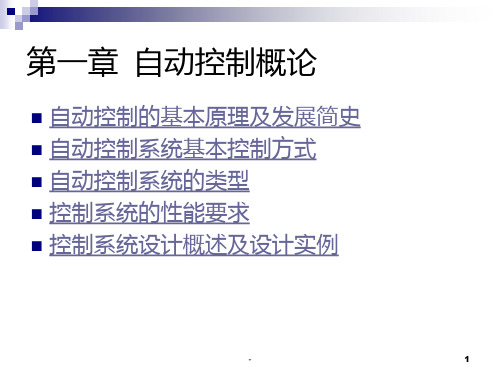
自动控制原理简介
自动控制系统的基本概念
自动控制系统
01
通过自动调节、控制、监视等手段,使某一设备或系统按照预
定的规律运行的系统。
自动控制系统的分类
1 2
按控制方式分类
开环控制系统、闭环控制系统、复合控制系统等 。
按被控参数分类
温度控制系统、压力控制系统、流量控制系统等 。
3
按控制规律分类
比例控制系统、积分控制系统、微分控制系统等 。
02
《自动控制原理》PPT课件_OK
例如对一个微分方程,若已知初值和输入值,对 微分方程求解,就可以得出输出量的时域表达式。 据此可对系统进行分析。所以建立控制系统的数学 模型是对系统进行分析的第一步也是最重要的一步。
控制系统如按照数学模型分类的话,可以分为线 性和非线性系统,定常系统和时变系统。
2021/7/21
2
自动控制原理
[线性系统]:如果系统满足叠加原理,则称其为线性系 统。叠加原理说明,两个不同的作用函数同时作用于 系统的响应,等于两个作用函数单独作用的响应之和。
[解]速度控制系统微分方程为:
a2 a1 a0 b1ug b0ug 对上式各项进行拉氏变换,得:
(s)(a2s2 a1s a0) Ug (s)(b1s b0)
即:
(s)
(b1s (a2s2
b0 ) a1s
a0 )
U
g
(s)
当输入已知时,求上式的拉氏反变换,即可求得输出
的时域解。
2021/7/21
2021/7/21
20
自动控制原理
[关于传递函数的几点说明]
❖ 传递函数的概念适用于线性定常系统,与线性常系 数微分方程一一对应。与系统的动态特性一一对应。
❖ 传递函数不能反映系统或元件的学科属性和物理性 质。物理性质和学科类别截然不同的系统可能具有 完全相同的传递函数。而研究某传递函数所得结论 可适用于具有这种传递函数的各种系统。
将上式求拉氏变化,得(令初始值为零)
(ansn an1sn1 a1s a0)Y(s) (bmsm bm1sm1 b1s b0)X (s)
G(s)
Y (s) X (s)
bm s m an s n
bm1sm1 b1s b0 an1sn1 a1s a0
《自动控制原理》课件

集成化:智能控制技术将更加集 成化,能够实现多种控制技术的 融合和应用。
添加标题
添加标题
添加标题
添加标题
网络化:智能控制技术将更加网 络化,能够实现远程控制和信息 共享。
绿色化:智能控制技术将更加绿 色化,能够实现节能减排和环保 要求。
控制系统的网络化与信息化融合
网络化控制:通过互联网实现远程控制和监控
现代控制理论设计方法
状态空间法:通过建立状态空间模型,进行系统分析和设计 频率响应法:通过分析系统的频率响应特性,进行系统分析和设计 极点配置法:通过配置系统的极点,进行系统分析和设计 线性矩阵不等式法:通过求解线性矩阵不等式,进行系统分析和设计
最优控制理论设计方法
基本概念:最优控制、状态方程、控制方程等 设计步骤:建立模型、求解最优控制问题、设计控制器等 控制策略:线性二次型最优控制、非线性最优控制等 应用领域:航空航天、机器人、汽车电子等
动态性能指标
稳定性:系统在受到扰动后能否恢复到平衡状态 快速性:系统在受到扰动后恢复到平衡状态的速度 准确性:系统在受到扰动后恢复到平衡状态的精度 稳定性:系统在受到扰动后能否保持稳定状态
抗干扰性能指标
稳定性:系统在受到干扰后能够 恢复到原来的状态
准确性:系统在受到干扰后能够 保持原有的精度和准确性
信息化控制:利用大数据、云计算等技术实现智能化控制
融合趋势:网络化与信息化的融合将成为未来控制系统的发展方向 应用领域:工业自动化、智能家居、智能交通等领域都将受益于网络化与 信息化的融合
控制系统的模块化与集成化发展
模块化:将复杂的控制系统分解为多个模块,每个模块负责特定的功能,便于设计和维护 集成化:将多个模块集成为一个整体,提高系统的性能和可靠性 发展趋势:模块化和集成化是未来控制系统发展的重要方向 应用领域:广泛应用于工业自动化、智能家居、智能交通等领域
自动控制原理(全套课件659P)

ppt课件 6
控制系统分析:已知系统的结构参数,分析系统的稳定性,求取系
统的动态、静态性能指标,并据此评价系统的过程称为控制系统分 析。
控制系统设计(或综合):根据控制对象和给定系统的性能指标,
合理的确定控制装置的结构参数,称为控制系统设计。 被控量 :指被控对象中要求保持给定值、要按给定规律变化的物理 量。被控量又称输出量、输出信号 。 给定值:系统输出量应达到的数值(例如与要求的炉温对应的电 压)。 扰动:是一种对自动控制系统输出量起反作用的信号,如电源电压
闭环控制是指系统的被控制量(输出量)
与控制作用之间存在着负反馈的控制 方式。采用闭环控制的系统称为闭环
控制系统或反馈控制系统。闭环控制
是一切生物控制自身运动的基本规律。 人本身就是一个具有高度复杂控制能
力的闭环系统。
优点:具有自动补偿由于系统内部和外 部干扰所引起的系统误差(偏差)的
能力,因而有效地提高了系统的精度。
ppt课件
12
方框图的概念
输入信号
方框 信号线 信号线
输出信号
• 方框 • 信号线
控制装置和被控对象分别用方框表示 方框的输入和输出以及它们之间的联接用带
箭头的信号线表示
• 输入信号 进入方框的信号 • 输出信号 离开方框的信号
ppt课件 13
开环控制系统方框图
输入量
控制装置
被控对象
输出量 (被控制量)
ppt课件
25
智能控制是从“仿人”的概念出发的。其方法包括学 习控制、模糊控制、神经元网络控制和专家控制等方法。
ppt课件
26
1.3 控制系统的分类
恒值系统和随动系统(按参考输入形式分类)
《自动控制原理》PPT课件
pi)
0
即K*=0时:闭环极点 si=开环极点pi
当K*→∞时,闭环特征方程 :
m
(s
i 1
zi )
1 K*
n
(s
i 1
pi)
0
K*→∞
m
(s
i 1
zi
)
0
即K*→∞时,闭环极点 si=开环零点zi
当m 时n, 有n-m 条的终点在无穷远点
n
n
K*
s
i 1 m
pi
i 1
s
zi
K*
lim
s
s
i 1
m
s
i 1
pi zi
lim snm s
12
说明:
1)有限开环零、极点:zi,pi 无限开环零、极点:∞
根轨迹起于开环极点,终于开环零点
2)在绘制其他参数根轨迹时,可能会出现 m>n 的情况,
H(s)
其中:Mi (s) (s zi1 )( s zi2 ); Ni (s) (s pi1 )( s pi2 ) i 1,2
开环零点:M1(s)M2(s) 0 开环极点:N1(s)N2(s) 0
闭环传递函数:s
K1 M1 ( s) N 2 s
K*M1(s)M2(s) N1(s)N2(s)
1 绘制依据 ——根轨迹方程
R(s) _
C(s) G(s)
闭环的特征方程:1 G(s)H(s) 0
H(s)
即:G(s)H(s) 1 ——根轨迹方程(向量方程)
用幅值、幅角的形式表示:
G(s)H(s) 1
《自动控制原理》PPT课件
i1
j1
i1
j1
f
G(s)
K G (1s 1)(22s2 22s 1) s (T1s 1)(T22s2 2T2s 1)
KG'
(s zi )
i1 q
(s pi )
i1
前向通道增益 前向通道根轨迹增益
KG'
KG
1 2 2 T1T2 2
反馈通道根轨迹增益
l
(s z j )
H(s) K H '
狭义根轨迹(通常情况):
变化参数为开环增益K,且其变化取值范围为0到∞。
G(s)H (s) K s(s 1)
(s) C(s) K R(s) s2 s K
D(s) s2 s K 0
s1,2
1 2
1 2
1 4K
K=0时 s1 0 s2 1
0 K 1/ 4 两个负实根
K值增加 相对靠近移动
i1
i1
负实轴上都是根轨迹上的点!
m
n
(s zi ) (s pi ) | s2 p1 135
i1
i1
负实轴外的点都不是根轨迹上的点!
二、绘制根轨迹的基本规则
一、根轨迹的起点和终点 二、根轨迹分支数 三、根轨迹的连续性和对称性 四、实轴上的根轨迹 五、根轨迹的渐近线 六、根轨迹的分离点 七、根轨迹的起始角和终止角 八、根轨迹与虚轴的交点 九、闭环特征方程根之和与根之积
a
(2k 1)180 nm
渐近线与实轴交点的坐标值:
n
m
pi zi
a= i1
i1
nm
证明
G(s)H (s) K '
m
(s zi )
i 1 n
自动控制原理第一章PPT课件
-
16
首次冲出太阳系 (美国伽利略号木 星 探 测 器 , 1989 年)
-
仿人机器人 (日本,2001年)
17
神舟五号载人航天成功(中国,2003年)
-
18
勇气号、机遇号火星探测器(美国,2004年)
-
19
“作为技术科学的控制论,对工程技术、生物
和生命现象的研究和经济科学,以及对社会研
究都有深刻的意义,比起相对论和量子论对社
(1)装置用方框表示 (2)信号用带箭头的线段表示 (3)信号引出点 (4)信号相加点(比较点)
-
27
方框(块)图 中的符号
控制系统框图的基本组成单元
元部件 信号(物理量)及传递方向 比较点 引出点 - 表示负反馈
-
返回 28
1-2自动控制系统基本控制方式
1. 开环控制 2. 闭环控制 3. 复合控制
近年来,我国在自动化仪表、工业调节器、数字控 制技术、航天工程、核动力工程等方面的研究和应用 取得了长足进展。
-
22
二.自动控制理论
1.定义 自动控制理论是研究自动控制共同规律的技术科 学. 2.分类 (1)经典控制理论:以传递函数为基础,主要研 究单输入—单输出,线性定常系统的分析和设计问题 。 (2)现代控制理论:主要研究具有高性能,高精 度的多变量多参数系统的最优控制问题。
-
25
三、自动控制系统
1.定义: 为了实现各种复杂的控制任务,将被控对象 和控制装置按照一定的方式连接起来组成的一 个有机总体。
控制装置(控制器):外加的设备或装置. 被控对象(process, plant, controlled system ):设备或生产过程.
自动控制原理课件(精品)

控制系统的应用实例
CATALOGUE
05
总结词
工业控制系统是自动控制原理应用的主要领域之一,涉及各种生产过程的控制和优化。
总结词
工业控制系统在现代化工业生产中发挥着至关重要的作用,是实现高效、安全、可靠生产的关键。
详细描述
随着工业4.0和智能制造的推进,工业控制系统正朝着网络化、智能化、集成化的方向发展,为工业生产的转型升级提供了有力支持。
详细描述
工业控制系统的目的是实现生产过程的自动化和智能化,提高生产效率、产品质量和降低能耗。常见的工业控制系统包括过程控制系统、电机控制系统、机器人控制系统等。
总结词:航空航天控制系统是保证飞行器安全可靠运行的关键技术之一。
总结词:智能家居控制系统是实现家庭智能化和舒适性的重要手段。
THANKS
准确性的提高方法
通过减小系统误差、优化控制算法和采用高精度传感器等手段,可以提高控制系统的准确性。
控制系统的分析与设计
CATALOGUE
04
系统分析方法用于评估系统的性能和稳定性,通过分析系统的响应和频率特性等指标来评估系统的性能。
总结词
系统分析方法包括时域分析法和频域分析法。时域分析法通过分析系统的阶跃响应、脉冲响应等时域指标来评估系统的性能和稳定性。频域分析法则通过分析系统的频率特性,如幅频特性和相频特性,来评估系统的性能和稳定性。
VS
闭环控制系统是一种控制系统的类型,其控制过程不仅取决于输入和系统的特性,而且还受到输出反馈的影响。闭环控制系统通过将输出量反馈到输入端,形成一个闭合的回路,从而实现对系统的精确控制。
闭环控制系统具有较高的精度和稳定性,因为它的输出会根据实际情况进行实时调整。但是,闭环控制系统的结构比较复杂,需要解决一些稳定性问题。
- 1、下载文档前请自行甄别文档内容的完整性,平台不提供额外的编辑、内容补充、找答案等附加服务。
- 2、"仅部分预览"的文档,不可在线预览部分如存在完整性等问题,可反馈申请退款(可完整预览的文档不适用该条件!)。
- 3、如文档侵犯您的权益,请联系客服反馈,我们会尽快为您处理(人工客服工作时间:9:00-18:30)。
Actual
DC rotatespeedn
motor
Output n
Process
10
Chapter 1 Introduction
1.2.3 Fundamental structure of control systems
Water exit Figure 1.2
+
ur
uf
e
amplifier
thermo meter
* Operating principle… * Feedback
ua=k(ur-uf)
M
Gear assembly
control(error)…
Figure 1.3
4
Chapter 1 Introduction
comparator
Actuator
Desired
rotate speed n
e
uk
a
ua
Regulator
Trigger
Rectifier
Reference
input ur
Error controller
u Feedbacksignal f
Techometer
measurement (Sensor) Fig. 1.9
+
5
Chapter 1 Introduction
4) A servo (following) control system
Input Tr
servopotentiometer
output Tc
load
Fig. 1.5
* principle……
-
servomechanism
M
+
servo motor
control is shown in figure 1.2.
float
* Operating
lever
p*rFineecdipblae…ck…
water
control……
entrance
2) A temperature Control system
(shown in Fig.1.3)
container
excess procreate
Desire population
government
+
-
(Family planning committee) Policy or
statutes
population society
census
* principle……
Fig. 1.6
* feedback(error)……
3) A DC-Motor control system
+
ur
Uk=k(ur-uf)
e
ua
regulator trigger
Uf (Feedback)
rectifier
* Principle…
Fig. 1.4
* Feedback control(error)…
DC motor
M
load
-
M techometer
Feedback signal Fig. 1.8
Float measurement (Sensor)
Actual water level Water container Output Process
9
Chapter 1 Introduction
For the Fig. 1.4, The DC-Motor control system
Gear assembly
+
float
motor - Water pool
M
amplifier Figure 1.1
resistance comparator
Desired water level
Input
amplifier Error
controller
Motor
Actuator Gearing
Valve
7
Chapter 1 Introduction
1.2.2 block diagram of control systems
The block diagram description for a control system : Convenience
x
x3 x1 + + e
-
x2
Signal
xxx
servomodulator
* feedback(error)……
6
Chapter 1 Introduction
5) A feedback control system model of the family planning
(similar to the social, economic, and political realm(sphere or field))
Automatic control theory
A Course ——used for analyzing and designing a automatic control system
1
整体 概述
一 请在这里输入您的主要叙述内容
二
请在这里输入您的主要 叙述内容
三 请在这里输入您的主要叙述内容
2
(variable)
Components (devices)
Adders (comparison)
e=x1+x3-x2
Fig. 1.7
Exampion
valve
For the Fig.1.1, The water level control system:
Chapter 1 Introduction
21 century — information age, cybernetics(control theory), system approach and information theory , three science theory mainstay(supports) in 21 century.
1.1 Automatic control
A machine(or system) work by machine-self, not by manual operation.
1.2 Automatic control systems 1.2.1 examples 1) A water-level control system
* Operating principle……
* Feedback control……
valve
Gear assembly
+
float
motor - Water pool
M
amplifier Figure 1.1
3
Chapter 1 Introduction
Another example of the water-level