伊莱斯ESDD说明书(2017修订)中英文翻译版
SD Series 防静电设备说明书

T h e S D S e r i e s is a range of surge protection devices combining unparalleled packing densities, application versatility, proven reliable hybrid circuitry, simple installation and optional ‘loop disconnect’facilities – features which make the series the ultimate surge protection solution for process equipment, I/O systems and communications networks.T h e e x c e p t i o n a l l y h i g h p a c k i n g d e n s i t i e s are the consequence of an ultra slim ‘footprint’ for individual modules which can thus ‘double-up’ as feedback terminals. Each module provides full hybrid surge protection for 2 and 3 wire loop protection.M o d u l e s w i t h a c o m p r e h e n s i v e r a n g e o f v o l t a g e r a t i n g s cover all process related signals such as RTDs, THCs, 4 to 20mA loops, telemetry outstations, shut-down systems and fire and gas detectors.O p t i o n a l‘l o o p d i s c o n n e c t’,is a feature which allows commissioning and maintenance to be carried out without removal of the surge protection device.This facility is provided by the SD07, SD16,SD32 and SD55 units. In addition, a thirdconnection on the field and safe side ofthe protector is provided in order toterminate screens safely.F o r t h r e e w i r e a p p l i c a t i o n s the speciallydesigned SD RTD(ResistanceTemperature Detector) and the SD32T3,(for separately powered 4-20mA loops)provide full 3-wire protection in a singlecompact unit. The recommended choicefor the protection of 3-wire pressuretransducers on low power circuits is theSD07R3.F o r h i g h e r b a n d w i d t h a p p l i c a t i o n s,theSDR series has been developed to meetthe demands of today’s highest speedcommunication systems.120V a n d240V A C v e r s i o n sare available for I/O andpower supplies up tothree Amps of loadcurrent.T e l e p h o n e n e t w o r k s can be protected bythe SDPSTN.O n e s i m p l e m a n u a l o p e r a t i o n clampsmodules securely onto DIN rail, whichautomatically provides the essential high-integrity earth connection.‘T o p-h a t’(T-s e c t i o n)D I N r a i l is generallysuitable for mounting SD modulesalthough for adverse environments, aspecially-plated version is available fromMTL Surge Technologies. Acomprehensive range of mounting andearthing accessories can also besupplied, see page 7 for furtherdetails.G U l t r a-s l i m s p a c e-s a v i n g d e s i g n;e a s y i n s t a l l a t i o n G M u l t i s t a g e h y b r i d p r o t e c t i o n c i r c u i t r y–10k Am a x i m u m s u r g e c u r r e n tG R a n g e o f v o l t a g e r a t i n g s--t o s u i t a l l p r o c e s s I/Oa p p l i c a t i o n sG H i g h b a n d w i d t h,l o w r e s i s t a n c e,R T D,P S T N a n d3-w i r e t r a n s m i t t e r v e r s i o n s a v a i l a b l eA n a l o g u e i n p u t s(h i g h-l e v e l)2-w i r e t r a n s m i t t e r s,4-20m A,c o n v e n t i o n a l a n d s m a r tThe SPDs recommended for use with ‘conventional’and ‘smart’ 4-20mA transmitters(fed by a well-regulated supply) are the SD32 and SD55, the choice depending upon the maximum working voltage of the system (32V and 55V respec-tively). The diagram illustrates a prime exam-ple of an application for which the fuse/dis-connect facility is particularly useful, however, both models are available in ‘X’ versions with-out the optional fuse/disconnect feature.A n a l o g u e i n p u t s(l o w-l e v e l)R T D sThese applications are best served using the SD RTD. F or optimum accuracy, the energising current should be chosen to ensure the voltage across the RTD does not exceed 1V over the full measurement range. When using a PT100 device, we recommend an energising current of 1mA.P h o t o c e l l s,T H C s,m V s o u r c e s a n d t u r b i n ef l o w m e t e r sThe SD07 or SD16 (depending upon the operational voltage) are the favoured choices for this application. SD07X and SD16X are also suitable.F I E L D C I R C U I T P R O T E C T E D C I R C U I T2-w i r e t r a n s m i t t e r s3w i r e R T D sp h o t o c e l l s,T H C s,m V s o u r c e s a n dt u r b i n e f l o w m e t e r sAlso, loops can be removed from the circuit for maintenance reasons or added without needing additional disconnect terminals. The following guide to selection suggests the most suitable SDs for a number of specific applications. For technical information, see the detailed specifications on the back page of this publication (some field circuit protection is shown for completeness).D i g i t a l(o n/o f f)i n p u t sS w i t c h e sSuitable SPDs for switches include the SD07, SD16, SD32 and SD55 modules – the choice depending upon the operating voltage of the sys-tem. The ‘X’ versions of these are also suitable.D i g i t a l(o n/o f f)o u t p u t sA l a r m s,L E D s,s o l e n o i d v a l v e s,e t cThe recommended choice for this application is the SD32 or SD32X.T e l e m e t r y(P S T N)T e l e m e t r y o u t s t a t i o n sThe SD PSTN has been designed specifically for the protection of signals transmitted on public switched telephone networks.A C s u p p l i e d e q u i p m e n tP L C,I/O s y s t e m sFor systems on 110-120V ac, the SD150X is the recommended choice and for 220-240V ac sys-tems, the SD275X is recommended.C o n t r o l l e r o u t p u t s (I/P c o n v e r t e r s)S w i t c h e sA l a r m s,L E D s,s o l e n o i d v a l v e s,e t c. T e l e c o m l i n eP L C,I/O s y s t e m s2-w i r e t r a n s m i t t e r s o r s e n s o r s4-20m A t r a n s m i t t e r s,c o n v e n t i o n a l a n ds m a r tWhere the TP48 is not an acceptable solution,either because of technical suitability ordifficulties in mounting, the SD16X, SD32X andSD55X are an excellent alternative.3-w i r e t r a n s m i t t e r s o r s e n s o r sVibration Sensors and 4-20mA loop processcontrol systems invariably require threewire connections, when powered from anexternal source.This may be accomplished in one unit by usingthe SD32T3 three terminal Surge ProtectionDevice (SPD).Because the SD32T3 protects all threeconductors within the same unit, higherprotection is achieved, as the SPD hybridcircuitry is common to all three wires.The SD07R3 is available for the protection of 3-wire pressure transducers on low powercircuits.4-w i r e t r a n s m i t t e r s o r s e n s o r sF l o w m e t e r s,l e v e l d e t e c t o r s,e t c.4-wire systems such as level detectors requiretwo SDs, one for the supply and the other forthe transmitter output. Generally the voltagesacross the pairs are similar and so therecommended choice would be a pair ofSD16X, SD32X or SD55Xs. However, mainspowered transmitters should be protected withan SD150X or 275X (depending upon supplyvoltage) for the supply inputs.Loadcells are catered for by MTL SurgeTechnologies’ LC30 which is suitable for both 4and 6-wire load cells.2-w i r e t r a n s m i t t e r o r s e n s o r3-w i r e t r a n s m i t t e r o r s e n s o r4-w i r e t r a n s m i t t e r o r s e n s o rS D P R O T E C T E D F I E L D C I R C U I T T O H O S T C I R C U I T2by fixing the metallic transmitter housing to the plant structure. This bond ensures the voltage difference between the signal conductors and the transmitter housing is below the transmitter’s insulation rating. Please note that the transmitters or sensors are connected to the ‘Protected Equipment’ terminals of the SD and not the ‘Field Cables’.C o m m u n i c a t i o n s y s t e m sR S 232, R S 422, R S 485The recommended choice for these applications isthe SD16R or SD32R depending on the maximumdriver signal.B u s p o w e r e d s y s t e m sThere are a variety of bus powered systemsspecially designed for the process industry. Theideal surge protection device for these systemsis the SD32R as it has a very high bandwidth anda modest in-line resistance.T y p i c a l A p p l i c a t i o n sTable 1 shows suitable SD devices for differentapplications. In some applications alternativedevices may be used, for example, where lowerin-line resistance or a higher voltage powersupply is used.Telematic have operationally tested therecommended SD series with representativehighways listed but no formal approval for theiruse in systems by the respective bodies hasbeen sought.R S 232, R S 422, R S 485B u s p o w e r e d s y s t e m s T a b l e 1 P R O T E C T E D F I E L D C I R C U I T S D P R O T E C T E D H O S T C I R C U I T A p p l i c a t i o n P r e f e r r e d S P D A l t e r n a t i v e Allen Bradley Data Highway Plus SD16R Foundation Fieldbus 31.25kbits/s voltage mode SD32R 1.0/2.5 Mbits/s SD55R HART SD32X SD32, SD32R Honeywell DE SD32X SD32, SD32R LonWorks FFT-10SD32R LPT-10SD55RTP-78SD07RIS78†SD32RModbus ‘& Modbus Plus (RS485)SD16RPROFIBUSDP SD32RPA (IEC 1158, 31.25 kbits/s)FP32RS232SD16SD16XRS422SD07RRS423SD07RRS485SD07RWorldRP (IEC 1158)SD32R31.25 kbits/s voltage mode1.0/2.5 Mbits/s SD55RE a r t h i n g The recommended earthing for field mounted devices has been illustrated previously but it is the earthing at the control panel that is more critical as there are usually a number of earthing systems, each with their own requirements. The earthing system illustrated here replaces the instrument 0V bond, the control system PSU bond and the IS earth with one single earth connection to meet all the design requirements and give the most effective protection against the effects of lightning induced surges.outdoor installation where there is a highlikelihood of both lightning induced transientsand combustible gases requires the installationof SPDs to prevent possible ignition of thegases. Areas seen particularly at risk includeflammable liquid storage tanks, effluenttreatment plants, distillation columns inpetrochemical works and gas pipelines.SPDs for transmitter protection should beinstalled in Zone 1 but sufficiently close to theZone 0 boundary to prevent high voltagesentering Zone 0. The distance from the SPDto Zone 0 should be less than one metrewhere possible. However, in practice the SPDwould normally be mounted on the transmitteror sensor housing which usually lies in Zone 1and is very close to Zone 0. Because there isonly a very small free volume, the SD Series issuitable for mounting in flameproof orexplosion proof enclosures.Z o n e 2The SD series is suitable for protecting electricalcircuits in Division 2, Zone 2 and can be usedwithout affecting the safety aspects of the circuit.Non-incendive (low-current) circuits can beprotected using any SD series unit mounted ineither the safe or hazardous area including thosewith the fuse disconnect facility. Non arcing (highcurrent) circuits can also be protected exceptthat SPDs with the fuse disconnect facility mayonly be mounted in the safe area. F or use inthese circuits the units must be mounted in asuitable enclosure, normally the minimumrequirements are IP54 and 7Nm resistance toimpact. The SD series is self certified byTelematic Ltd as being suitable for this purpose.C e r t i f i c a t i o nIntroducing surge protection into IntrinsicallySafe (IS) circuits is trouble free as long as thecurrent and power parameters are notexceeded. In the SD Series, the SD**X, SD**R,SD**R3, SD RTD and SD**T3 all have ATEXcertification for use in IS circuits located inZones 0, 1 or 2. The certification parametersfor the SD**X and SD**T3 are:E E x i a I I C T 4, Li = 0.22mHIi = 260mA for Ui up to 20VIi = 175mA for Ui up to 26VIi = 140mA for Ui up to 28VIi = 65mA for Ui up to 60VThe certification parameters for the SD**R,SD**R3 and SD RTD are:E E x i a I I C T 4, Li = 0Ii = 260mA for Ui up to 60VThe power rating for each of the above isdependent on the table shown below.Pi = 1W (–30°C to +75°C)Pi = 1.2W (–30°C to +60°C)Pi = 1.3W (–30°C to +40°C)The SD** Series are classifed as simpleapparatus and are intended for use in Zone 2 orsafe areas only, because their fuses are not fullyencapsulated.the tops of individual SPDs. Both methods can be used conjointly. Replaceable fuses or solid links are available in packs of 5 (SD-F25, SD-F05 and SD-LNK).M o u n t i n g a c c e s s o r i e sISP7000Insulating spacerTHR2Standard DIN rail, 35mm x 7.5mmTHR7000T-section DIN rail, specially nickel plated,35mm x 7.5mm, 1m lengthE a r t h i n g /e a r t h r a i l a c c e s s o r i e sETL7000Earth terminal, DIN rail mountedIMB57Insulated mounting block (two needed)ERB57S Earth rail bracket, straightERB57O Earth rail bracket, offsetERL7Earth rail, 1m lengthETM7Earth terminal, pack of 50T a g g i n g a c c e s s o r i e sTAG57Tagging strip, 1m lengthTGL57Tagging strip labels, set of 10 x 0.5mBRI7000Barrier identifierBIL7000Barrier indentification labels, sheet of 120BIL7000L Barrier identification labels, A4 sheet of 126E n c l o s u r e sDX070Enclosure for up to 9 x SD series SPDsDX170Enclosure for up to 22 x SD series SPDsDX430Enclosure for up to 58 x SD series SPDsA c c e s s o r i e s (r e p l a c e m e n t )SD-F25Replaceable fuse pack - 250mA standard(available in packs of 5)SD-F05Replaceable fuse pack - 50mA special(available in packs of 5)SD-LNK Solid Link (available in packs of 5)D I M E N S I O N S (m m )C o u n t r y S t a n d a r d C e r t i f i c a t e /A p p r o v e d f o r P r o d u c t(A u t h o r i t y )F i l e N o .BASEEFA EN 50014:1997BASEEFA EEx ia IIC T4*SD07X,SD16X,SD32X,(EC)EN 50020:200202ATEX0211X SD55X,SD07R, SD16R,EN 50284:1999SD32R,SD55R,SDRTD,SD32T3,SD07R3,SD16R3,SD32R3,SD55R3CSA/C/US CSA C22.2 No. 0-M1991LR 103652-3EEx ia Class 1,SD07,SD16,SD32,SD55, (Canada, USA)CSA C22.2 No. 157-M1992Groups A, B SD07X,SD16X,SD32X, UL 913, 5th edition C and D, T4SD55X,SD07R,SD16R,CSA C22.2 No. 142-M1987Class 1, Div 2 SD32R,SD55R,SDRDT , CSA C22.2 No. 213-M1987Groups A,B,C, D T4SD32T3,SD07R3,SD16R3, UL 508, 17th edition SD32R3,SD55R3UL 1604, 3rd edition UL UL 497B Listed E220693Isolated loop SD07,SD16,SD32,SD55(USA)communication SD07X,SD16X,SD32X circuits SD55X,SD07R,SD16R SD32R,SD55R,SD07R3SD16R3,SD32R3,SD55R3SD32T3,SD55T3, SD07X3,SD16X3,SD32X3,SD55X3,SDRTD UL UL 1449 2nd Edition E217523AC power SD150X,SD275X (USA, Canada)Recognised Component protection Austel AS/NZ3548:1995__Private Wire SD07R (Australia)AS/NZS4117:1996TS001: 1997901-107 R e v H 5/03/06Note: all figures are typical at +25°C unless otherwise stated; *standard fuse; +over full working temperature range; †at 20mA with a 250mA standard fuse; ‡these units need external 3A fuses; ^Signal; **Power & Common; maximum energising current depends upon RTD resistance.820(10/350µs )2.5kA1.0kA (SD150X and SD275X only)R e s p o n s e t i m e<1nsR T D r e s i s t a n c e r a n g e (S D R T D )10 to 1500ΩD e g r a d a t i o n a c c u r a c y (S D R T D a t 1m A )0.1% (RTD resistance >100Ω)0.1Ω(RTD resistance < 100Ω)A m b i e n t t e m p e r a t u r e–40°C to +80°C (working)–40°C to +80°C (storage)H u m i d i t y5 to 95% RH (non-condensing)C a t e g o r y t e s t e dA2, B2, C1, C2, C3O v e r s t r e s s e d f a u l t m o d e i n =3k A12kA9kA (SD150X and SD275X only)I m p u l s e d u r a b i l i t y (8/20μs )10kA6.5kA (SD150X and SD275X only)T e r m i n a l s2.5mm 2(12 AWG)M o u n t i n gT-section DIN-rail(35 x 7.5 or 35 x 15mm rail)W e i g h t70g approximatelyC a s e f l a m m a b i l i t yUL94 V-2A C d u r a b i l i t y1A rms , 5TS e r v i c e c o n d i t i o n s80kPa - 160kPa5% - 95% RHE M C c o m p l i a n c eTo Generic Immunity Standards,EN 50082, part 2 for industrialenvironmentsR &T T E c o m p l i a n c eEN 50082-2 : 1995EN 41003 : 1999EN 60950 : 1992(not applicable to SD150X andSD275X)L V D c o m p l i a n c eSD150X & SD275XEN 60950 : 1992EN 61010 : 1995SD PSTNEN 41003 : 1999I E C c o m p l i a n c eEN 61643-21:2001T o o r d e r s p e c i f y -Order by module, as listed in the specification table and/or accessory part numbers as defined on page 7.Note: In accordance with our policy of continuous improvement, we reserve the right to change the product’s specification without notice.D e f i n i t i o n s o f t e r m i n o l o g y u s e d i n t a b l e 1W o r k i n g v o l t a g e (U n )Maximum voltage between lines or lines/ ground for the specified leakage current 2M a x i m u m l e a k a g e c u r r e n t (I c )Maximum current drawn by the SPD at the working voltage 3M a x i m u m c o n t i n u o u s o p e r a t i n g v o l t a g e (U c )Maximum voltage that can be applied to the protected terminals without damage 4V o l t a g e p r o t e c t i o n l e v e l (U p )Peak output voltage after injection of test impulse from 1kV/μs generator (often known as ‘let-through’ voltage)5B a n d w i d t h Frequency range up to which ac signals can be transmitted without undue attenuation; 3dB into 50Ω(600Ωfor the SD PSTN )A p p r o v a l s * See page 6 for further details M T L S u r g e T e c h n o l o g i e s Power Court, Luton, Bedfordshire, England LU1 3JJ Tel:+44(0)1582 723633 Fax: +44 (0)1582 422283E-mail:***********************:A m e m b e r o f t h e M T L I n s t r u m e n t s G r o u p p l c Blue colour signifies products ATEX certified EEx ia IIC T4.。
伊莱斯伺服 ESDB说明书1.01

安全注意事项本手册为ESDB系列伺服驱动器的操作指导手册。
本手册提供给使用者选型、安装、参数设置、现场调试、故障诊断及日常保养与维护的相关注意事项及指导。
为正确使用本系列伺服驱动器,请事先认真阅读本手册,并请妥善保存以备后用。
设备配套客户请将此手册随设备发给最终用户。
在本手册中,安全注意事项有以下几类:1、产品检查交流伺服驱动器必须与性能匹配的伺服电机配套使用。
损坏或有故障的产品不可投入使用,否则可能会导致火灾或设备故障。
如果用户自配电机,请联系我公司技术人员,否则不能保证驱动器正常运行。
2、安装禁止将产品暴露在有水气,腐蚀性、可燃性气体的场合使用,否则会导致触电或火灾。
禁止将产品用于阳光直射,灰尘、盐分及金属粉末较多的场所。
禁止将产品用于有水、油及药品滴落的场所。
3、配线制动电阻必须按指定方式连接,否则会损坏驱动器。
电源,否则会造成设备损坏、触电或火灾。
电机输出端子和电机接线端子4、操作注意通电前应确认伺服驱动器和伺服电机已安装稳妥,固定牢固,电源电压及接线正确。
必须先分开机械设备的联轴器或皮带等,设定值,测试伺服电机正常运行后,才能将负载接上,否则会损坏设备,发生故障。
运行时,禁止触摸任何旋转中的电机零件,否则可能会造成人员受伤。
设备运行时,禁止移动连接电缆,否则可能会造成人员受伤或设备损坏。
禁止频繁接通、关闭电源,如果需要请控制在一分钟一次以下。
5、故障处理除指定的专业人员外,请勿进行连接、安装、操作、拆卸与维修工作,有触电和损坏设请勿自行进行改造,有触电受伤的危险。
目 录第一章 产品说明 (1)1.1铭牌型号说明 (1)1.2驱动器各部分名称 (2)1.3伺服驱动器技术规范 (3)第二章 安装 (4)第三章 配线 (7)3.1外围设备的连接 (7)3.2伺服驱动器接线 (8)3.2.1 电源接线实例 (8)3.2.2 伺服驱动器标准接线图 (9)3.2.3 绝对值编码器接线 (10)3.2.4 旋转变压器接线 (10)第四章 接口 (11)4.1电源接线端子定义 (11)4.2CN1编码器反馈端子定义 (11)4.3CN2控制端子定义 (12)4.4CN3通信接口端子定义 (13)4.5开关量输入输出接口原理 (14)4.5.1 开关量输入接口原理 (14)4.5.2 开关量输出接口原理 (14)4.6位置脉冲指令输入接口原理 (15)4.7模拟量输入输出接口原理 (18)4.7.1 模拟指令输入接口原理 (18)4.7.2 模拟量输出接口原理 (19)4.8编码器信号输入输出接口原理 (19)4.8.1 编码器信号输出CN2接口原理 (19)4.8.2 编码器信号输入CN1接口原理 (20)第五章 面板操作 (21)5.1面板操作概述 (21)5.2菜单结构 (21)5.2.1状态参数查看操作 (22)5.2.2参数编辑操作 (23)5.2.3特殊功能参数 (24)第六章 通信功能 (25)6.1MODBUS通信概要 (25)6.2MODBUS通信协议 (25)第七章 参数与功能 (31)7.1参数一览表 (31)7.2参数设置详解 (39)7.3数字输入DI功能定义 (54)7.4数字输出DO功能定义 (56)第八章 报警与处理 (58)第九章 运行与调试 (61)9.1驱动器通电 (61)9.2空载运行调试 (61)9.3控制功能调试 (62)9.3.1 位置控制 (62)9.3.2 速度控制 (64)9.3.3 转矩控制 (65)第十章 伺服电机部分 (67)10.1铭牌型号说明 (67)10.2电机各部分名称 (68)10.3伺服电机的安装 (68)10.4伺服电机端子定义及连线 (73)附录A (75)n电机适配表 (75)n电缆型号 (76)n电机信号线(编码器线)电缆型号说明 (77)n电机动力线电缆型号说明 (77)第一章 产品说明1.1铭牌型号说明1、铭牌说明图1.1 伺服驱动器铭牌说明2、型号说明ESDB—15A E C开发顺序号编码器型号:E:增量式编码器P:省线式编码器S:绝对值编码器R:旋转变压器电压等级:A:220VB:380V输出功率:15×0.1KW=1.5KW产品序列号:ESDB图1.2伺服驱动器型号说明1.2驱动器各部分名称连接错误时易造成驱动器损坏。
ELSD 2000ES 操作手册(中文)
等待…………………………………………………………………………………………………………11 运行…………………………………………………………………………………………………………11
菜单窗口 ………………………………………………………………………………………………………… 12 建立一次运行运行………………………………………………………………………………………………12 方法窗口 ………………………………………………………………………………………………………… 12 3.10.1 选择以前保存方法………………………………………………………………………………………13 3.10.2 编辑现有方法……………………………………………………………………………………………13 3.10.3 建立新方法 ………………………………………………………………………………………………14
开始程序 ………………………………………………………………………………………………………… 19 关机程序 ………………………………………………………………………………………………………… 20 优化程序 ………………………………………………………………………………………………………… 21 4.7.1 4.7.2 撞击器‘关’的模式……………………………………………………………………………………21 撞击器‘开’的模式……………………………………………………………………………………22
-
2
-
1. 简介
1.1 ELSD 2000ES 介绍
Alltech 2000ES 型 蒸 发 光 散 射 检 测 器 ( Evaporative Light Scattering Detector 2000 Enhanced Sensitivity )设计用于高效液相色谱系 统,分析任何挥发性低于流动相的化合物。ELSD ELSD 的应用范围包括: 碳水化合物, 药物, 脂类, 甘油三脂,未衍生的脂肪酸和氨基酸,聚合物, 表面活化剂,营养滋补品,及组合分子库等。 蒸发光散射检测器消除了常见于其他 HPLC 检测器的问题。示差检测受溶剂前沿峰的干扰使 得分析复杂化,并且由于对温度极其敏感使得基 线很不稳定,与梯度洗脱不相容。另外,示差检 测器的响应不如 ELSD 灵敏。而低波长紫外检测 器在急变梯度条件下受基线漂移的困扰,并要求 被分析化合物带有发色团。 ELSD 则不受这些限 制。不同于这些检测器,ELSD 能在多溶剂梯度的 情况下获得稳定的基线,使得分辨率更好、分离 速度更快。另外,因为 ELSD 的响应不依赖于样 品的光学特性,所以 ELSD 检测时样品不要求带 有发色团或荧光基团。 ELSD 2000ES 提供当今最先进的蒸发光散射 检测技术。 2000ES 改进了光路和电路设计,为 HPLC 分析提供更高的灵敏度。 以连接闭合为基础 的磁性联锁开关提供重要的安全保障,当光路元 件连接完成后防止激光光源的泄漏。雾化器设计 为坚固耐用和重现性良好。数字气体流量计令用 户可直接从面板上或者通过 PC 机调节气体流量。 现在有两种操作模式供用户选择:撞击器开 (Impactor On)和撞击器关(Impactor Off) 。撞击 器关模式最适用于高有机含量的流动相或者高水 含量/低流量的流动相(≤1.0mL/min)时分析非挥 发性样品。由于将所有雾化后的样品全部送到光 检测池检测,所以对于这些应用这种模式具有最 佳灵敏度。撞击器开模式最适用于高流量或者高 含水量流动相时(最高可达 5.0mL/min,包括急变 梯度时)分析非挥发性样品,以及分析半挥发性 样品。在撞击器开模式下,气溶胶中较大液滴被 旁路除去,因而在漂移管温度很低情况下获得最 佳此流动相蒸发。只有 ELSD 2000ES 能够同时提 供两种操作模式,使得所有可能的流动相和样品 均能获得最佳检测灵敏度和基线稳定性。 ELSD 2000ES 有 几 种 仪 器 控 制 方 式 可 供 选 择。仪器参数直接显示在前面板上,并可通过前 面板上的触摸键和数字键盘直接控制。内置的软 件可提供一系列直观的屏幕用于存储和编辑最多 十种方法;设置声音报警,故障继电器,和满量 3
Leuze electronic S300 Safety Position Switch 说明书
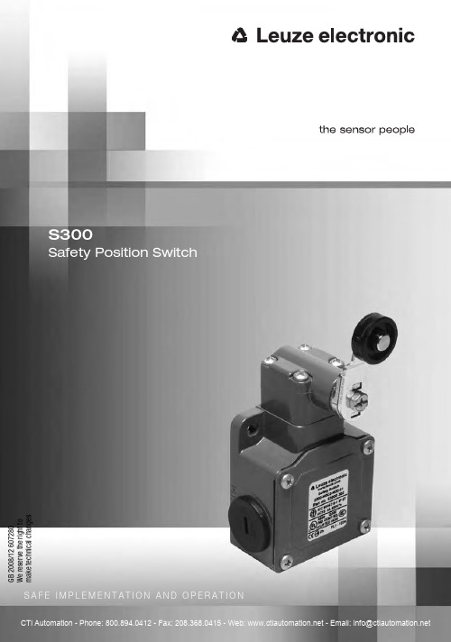
S300Safety Position SwitchS A F E I M P L E M E N T A T I O N A N D O P E R A T I O N G B 2008/12 607280W e r e s e r v e t h e r i g h t t o m a k e t e c h n i c a l c h a n g e s1About this document (5)1.1Other applicable documents (5)1.2Used symbols and signal words (6)2Safety (7)2.1Proper use (8)2.2Competent personnel (9)2.3Responsibility for safety (10)2.4Exemption of liability (10)3Device description (11)4Functions (13)5Applications (13)6Mounting (14)6.1Adjusting the switching and approach direction (14)6.2Mounting the Safety Position Switch (16)7Electrical connection (20)7.1Connecting the contact block (20)8Setting the device into service (21)9Testing (22)9.1To be performed prior to the initial start-up by competent personnel (22)9.2To be performed periodically by competent personnel (22)9.3To be performed daily by the operating personnel (23)10Cleaning (24)11Disposing (24)12Service and support (24)13Accessories (24)14Technical data (25)15EC Declaration of Conformity (28)About this document 1About this document1.1Other applicable documentsThe information on the S300 Safety Position Switch is divided into two documents.Document "Application information" contains only the most important safety notices.ªFor the safe implementation, testing and operation, download document "Safe implementation and operation of the S300" from/***********************************************tel.+4981415350-111.Table 1.1:Documents on the S300 Safety Position SwitchPurpose and target group Title SourceDetailed information for all users Safe implementation andoperation (this document)On the Internet, download from:/s300Basic information for technicians and machine operators Application information Print document part no.607238included in the delivery contents ofthe productAbout this document 1.2Used symbols and signal wordsT able 1.2:Warning symbols and signal wordsT able 1.3:Other symbolsSymbol for dangersNOTICESignal word for property damageIndicates dangers that may result in property damage if the measures for danger avoidance are not followed.CAUTIONSignal word for minor injuryIndicates dangers that may result in minor injury if the measures for dan-ger avoidance are not followed.WARNINGSignal word for severe injuryIndicates dangers that may result in severe or fatal injury if the measures for danger avoidance are not followed.DANGERSignal word for life-threatening dangerIndicates dangers that will result in severe or fatal injury if the measures for danger avoidance are not followed.Safety2SafetyBefore using the Safety Position Switch, a risk evaluation must be performed according to valid standards (e.g. EN ISO12100-1, EN ISO13849-1, EN ISO14121). For mounting, operating and testing, document "Safe implemen-tation and operation of the S300" as well as all applicable national and interna-tional standards, regulations, rules and directives must be observed (e.g.machinery directive, low-voltage directive, work-equipment directive, safety regu-lations, accident-prevention regulations, EN1088, EN ISO13849-1, EN60204-1, EN954-1). Observe and print out relevant and supplied documents and distribute to the affected personnel.ªBefore beginning work with the Safety Position Switch, completely read and understand the documents applicable to the respective task.The following standards apply for the risk evaluation at the protective device prior to using the Safety Position Switch:•EN ISO14121, Safety of machinery, risk evaluation•EN ISO12100-1, Safety of machinery•EN ISO13849-1, Safety-related parts of control systemsThe realizable category of the integration in control circuits according to EN ISO13849-1 and EN954-1 is dependent on the used contact block and wiring.In particular, the following national and international legal regulations apply for the start-up, technical inspections and work with Safety Position Switch:•Machinery directive 2006/42/EC•Low voltage directive 2006/95/EC•Use of work equipment directive 89/655 EEC•Safety regulations•Accident-prevention regulations and safety rulesSafety 2.1Proper useTo ensure proper personnel protection, the Safety Position Switch must be mounted, connected and started-up by trained personnel. It must be in perfect condition and inspected regularly. The switching process must only be triggered by an actuator approved for this Safety Position Switch that is form-fitting with positive actuation.The rules and regulations for protection and safety at work and the recognised safety-related rules and regulations must be observed. These include:•EN 1088, Interlocking devices associated with guards •EN ISO 13849-1, Safety-related parts of control systems •EN 60204-1, Electrical equipment of machinesS300 Safety Switches must be connected in such a way that a dangerous state can only be activated while the protective device is closed and so that the dangerous state stops upon opening of the protective device. It must not be used if the point of operation can be accessed during the lag time before the dangerous state has ended.Connection conditions:•the dangerous state can only be activated while the protective device is closed•opening the protective device while the machine is running triggers a STOP command and ends the dangerous stateFurthermore, the S300 Safety Position Switch must not be used under the following conditions:•the actuation surface (e.g. of the machine or sliding gate) for the actuator is not form-fitting with positive actuation•rapidly changing ambient temperature (leads to condensation)•in the event of strong physical shocks•in explosive or easily flammable atmospheres •the mounting locations are not sufficiently stable•the safety of multiple persons is dependent on the function of this Safety Switch (e.g. nuclear power plants, trains, aircraft, motor vehicles, incinera-tors, medical devices)Handling the Safety Position Switch:ªObserve the permissible environmental conditions for storage and operation (see chapter14 "Technical data").For machines with longer slowdowns, a Safety Locking Device must be used.Safety ªImmediately replace damaged Safety Position Switch according to theseinstructions.ªUse cable gland, insulation materials and connecting wires of the appropriate protection rating.ªProtect the Safety Position Switch from penetrating foreign bodies (e.g. shav-ings, sand and blasting agent).ªBefore performing painting work, cover the actuation head, actuator and name plate.ªImmediately clean any contamination from the Safety Position Switch that impacts function according to these instructions.ªMake no structural changes to the Safety Position Switch and/or actuator.ªThe switching direction may only be changed following an adequate risk eval-uation and according to the dangerous direction of movement.2.2Competent personnelPrerequisites for competent personnel:•suitable technical training•knows the rules and regulations for occupational safety, safety at work andsafety technology and can assess the safety of the machine•knows the instructions for the Safety Position Switch and the machine•was instructed by the responsible individuals on the mounting and operationof the machine and of the Safety Position SwitchSafety2.3Responsibility for safetyManufacturer and operator of the machine must ensure that the machine and implemented Safety Position Switch function properly and that all affected persons are adequately informed and trained.The type and content of all imparted information must not lead to unsafe actions by users.The manufacturer of the machine is responsible for:•safe machine construction•safe implementation of the Safety Position Switch•imparting all relevant information to the operator•adhering to all regulations and directives for the safe starting-up of themachineThe operator of the machine is responsible for:•instructing the operating personnel•maintaining the safe operation of the machine•adhering to all regulations and directives for occupational safety and safetyat work•regular testing by competent personnel2.4Exemption of liabilityLeuze electronic GmbH + Co. KG is not liable in the following cases:•Safety Position Switch is not used as intended•safety notices are not adhered to•mounting and electrical connection are not properly performed•proper function is not tested (see chapter9 "T esting")•changes to the Safety Position Switch and/or actuatorDevice description3Device descriptionThe Safety Position Switch of the S300 series is an electro-mechanical switching device in a housing made of metal; the device satisfies protection rating IP 67.Available as actuator are a roller plunger and a roller lever.1Actuator head 2Actuator3Housing cover4Name plate (connection data, production code and year of manufacture)Table 3.1:S300 Safety Position SwitchArticlePart No.DescriptionS300-M0C3-M20-156**** ****NC + 1NO, roller plunger, 3 cable entriesS300-M13C3-M20-156**** ****NC + 1NO, roller plunger, 3 cable entries S300-M0C3-M20-3163000 3021NC + 1NO, roller lever, 3 cable entriesS300-M13C3-M20-3163000 3032NC + 1NO, roller lever, 3 cable entriesDevice descriptionFigure 3.1:Dimensions S300-M0C3-M20-15 and S300-M13C3-M20-15 in mmFigure 3.2:Dimensions S300-M0C3-M20-31 and S300-M13C3-M20-31 in mmFunctions The actuator head can be turned in 90° increments and set to 4 approach direc-tions. The roller lever can be mounted with a 180° rotation and can be positioned in 10° increments.10°Figure 3.3:Adjustment options4FunctionsThe Safety Position Switch signals to the safety switching device whether the protective device is closed. Depending on actuator and set actuation directions, the Safety Position Switch can also signal alternating directions of danger situa-tions. Release of the actuator closes the safety contacts; pressure on the actuator forces opening of the safety contacts upon opening of the protective device (e.g.a sliding gate). As a result, the machine can only be switched on if the protectivedevice is closed.5ApplicationsThe Safety Position Switch is suitable for e.g. the following protective devices:•turning or sliding protective hoods and protective flaps•laterally moveable protective gratings or sliding gates•machine-actuated supplementary cut-off (e.g. in combination with otherSafety Switches)Mounting6Mounting6.1Adjusting the switching and approach directionªLoosen the 4 screws on the actuator head.ªLift the actuator head.WARNINGSerious accidents may result if the Safety Position Switch is not mounted properly!The protective function of the Safety Position Switch is only ensured if appropri-ately and professionally mounted for the respective, intended area of application.ªMounting may only be performed by competent personnel.ªObserve standards, regulations and these instructions.ªObserve mounting conditions exactly.ªUse separate mechanical limit stop (see figure 6.3).ªSet the distances to the actuator and its angles so that it is impossible to cir-cumvent or encompass the protective device.ªProtect the housing from materials penetrating the enclosure (environmentalconditions see chapter 14 "Technical data").ªTest to ensure proper function.WARNINGSevere injuries may result if the switching function is not set properly!ªSet the switching direction so that the NC contacts open upon opening of the protective device.Mounting ªIf necessary, set the internal plunger to the correct switching direction in 90° increments (relative to the NC contacts).ªPlace the actuator head on the Safety Position Switch in the desired approach direction.ªTighten the 4 screws on the actuator head with 0.8–1.2 Nm.ªIf necessary, loosen the screw on the roller lever and adjust the roller lever (rotate 180° and/or turn in 10° increments).ªIf necessary, tighten the screw on the roller lever with 0.8–1.2 Nm.10°Mounting6.2Mounting the Safety Position SwitchMounting conditionsThe stop command must be triggered through pressure on the Safety Position Switch upon opening of the protective device, never by releasing the Safety Posi-tion Switch.Correct WrongFigure 6.1:Mounting example with a turning protective deviceCorrectWrongFigure 6.2:Mounting example with a sliding protective deviceMounting Correct WrongFigure 6.3:Mechanical limit stop (1)Correct Mechanical load exceedsspecifications; stability notensuredWrongFigure 6.4:Roller plunger actuationMountingCorrectMechanical load exceedsspecifications; stability not ensuredWrongFigure 6.5:Roller lever actuationMountingMountingPrerequisites for mounting:•actuation direction is set•fully assembledNOTICEThe Safety Position Switch may be damaged if mounted improperly! Safety Position Switch is not suitable for large mechanical loads.ªObserve mounting conditions and dimensions exactly.ªMount covers to protect against foreseeable damages.ªSelect the mounting location so that the following conditions are satisfied:•should be form-fitting to protect against changes in position; securedmounting is possible•corresponding actuating element (moveable guard, control cam) is suffi-ciently secured against changes in position and the actuator is actuated with positive force•accessible to qualified personnel for testing and replacementªPosition washers and screw down Safety Position Switch with 2–3Nm.Electrical connection7Electrical connectionWARNINGSerious accidents may result if the electrical connection is faulty!ªElectrical connection may only be performed by competent personnel.7.1Connecting the contact blockPrerequisites:•temperature stability of the cable insulation material must be greater thanthe maximum temperature of the housing (see chapter14 "Technical data")•cable gland with appropriate protection rating•maximum current load is observed (see chapter14 "Technical data")Figure 7.1:1NC + 1NO (S300-M0C3-M20-15, S300-M0C3-M20-31)Figure 7.2:2NC + 1NO (S300-M13C3-M20-15, S300-M13C3-M20-31)DANGERRisk of death by electric shock!ªInterrupt the voltage supply to the Safety Position Switch.ªUnscrew the housing cover.ªConnect the contact block according to the circuit diagram.Setting the device into serviceFigure 7.3:Connection example S300-M0C3-M20-15ªTighten cable terminal screws with 0.6–0.8Nm.ªTighten the housing cover with 0.8–1.2Nm.8Setting the device into servicePrerequisites:•Safety Position Switch is mounted and connected according to theseinstructions•operating personnel have been trained in the correct useªTest the function of the Safety Position Switch (see chapter9 "Testing").The Safety Position Switch is then ready for use.Testing9TestingS300 Safety Position Switches are maintenance-free. Nevertheless, they must be replaced after maximum 5,000,000switching cycles.ªAlways replace the entire Safety Position Switch including actuator.ªFor the testing intervals, observe nationally applicable regulations.ªDocument all tests in a comprehensible manner.9.1To be performed prior to the initial start-up by competent personnelªCheck whether the Safety Position Switch is operated according to its specified environmental conditions (see chapter14 "Technical data").ªCheck whether the Safety Position Switch is mounted in a form-fitting manner according to its specifications (see chapter6.2 "Mounting the Safety PositionSwitch").ªTest whether the actuator is form-fitting with positive actuation.ªCheck whether the switching direction was set correctly and the STOP com-mand is output as soon as opening of the protective device begins.ªTest to ensure proper mechanical and electrical function (see chapter9.2).9.2To be performed periodically by competent personnelMechanical functionªStop the dangerous state and open the protective device.ªCheck that the components are securely fastened.ªTest the cable entry for leaks.ªCheck Safety Position Switch and actuator for damage, deposits, deformation and wear.ªManually actuate roller lever or roller plunger (actuator) several times and check for ease of motion.ªCheck the actuating surface (e.g. of the machine or sliding gate) for the actua-tor for wear.ªTest the interaction of the actuation surface and the actuator to ensure that it is form-fitting with positive actuation.Testing Electrical functionWARNINGSevere injuries may result if tests are not performed properly!ªMake certain that there are no persons in the danger zone.ªStop the dangerous state and open the protective device.ªMake certain that the machine cannot be started while the protective device is open.ªClose the protective device and start the machine.ªTest several times whether the machine stops upon opening of the protective device.ªTest whether the dangerous state ends before the point of operation can be reached.9.3To be performed daily by the operating personnelWARNINGSevere injuries may result if tests are not performed properly!ªMake certain that there are no persons in the danger zone.ªStop the dangerous state and open the protective device.ªCheck the Safety Position Switch and actuator for damage or tampering.ªMake certain that the machine cannot be started while the protective device is open.ªClose the protective device and start the machine.ªTest whether the machine stops upon opening of the protective device.Cleaning10CleaningThere must be no soiling (e.g. shavings and dust) present, especially in the actu-ator of the Safety Position Switch.Prerequisites for cleaning:•protective device is opened and machine is switched off•voltage supply to the Safety Position Switch is interruptedªRegularly clean the Safety Position Switch, actuator and actuation surface (e.g.of the machine or sliding gate) (e.g with a vacuum cleaner).11DisposingªThe nationally valid regulations for electro-mechanical components are to be observed when disposing.12Service and supportContact data:Leuze electronic GmbH + Co. KGLiebigstraße 4D-82256 FürstenfeldbruckPhone: +49 8141 5350-11113AccessoriesThere are no accessories available for the Safety Position Switch.Technical data14Technical dataTable 14.1: GeneralSwitch type Interlock device without guard interlockingin accordance with EN 1088Actuator Plunger actuator, roller actuator with lever,mountedApproach actuation directions Plunger actuator: 1 x above, 4 x side (90°)Roller actuator: 360°, 4 x lateral (90°) Switching direction of plunger actuator Both sidesSwitching direction of roller actuator Left-right one side, both sidesApproach speed S300-M0C3-M20-15 with angle of approach = 15°, 30°, 45°min. 0.04mm/s, 0.02mm/s, 0.01mm/s max. 1.0m/s, 0.5m/s, 0.3m/sApproach speed S300-M13C3-M20-15 with angle of approach = 15°, 30°, 45°min. 4.0mm/s, 2.0mm/s, 1.0mm/s max. 1.0m/s, 0.5m/s, 0.3m/sApproach speed S300-M0C3-M20-31with angle of approach = 15°, 30°, 45°, 60°min. 0.07 mm/smax. 2.5m/s, 1.5m/s, 1.0m/s, 0.75m/sApproach speed S300-M13C3-M20-31 with angle of approach = 15°, 30°, 45°, 60°min. 9mm/s, 8mm/s, 7mm/s, 7mm/s max. 2.5m/s, 1.5m/s, 1.0m/s, 0.75m/sActuating path S300-M0C3-M20-154mmActuating path S300-M13C3-M20-153mmActuating path S300-M0C3-M20-3160°Actuating path S300-M13C3-M20-3143°Actuation force of plunger actuator min. 11 NActuation force of roller actuator min. 0.1 NmMechanical life time without actuator acc. toIEC60947-5-15,000,000switching cycles Actuation frequency acc. to IEC60947-5-1max. 3600 per hourLife time according to EN ISO13849-1on requestTechnical dataT able 14.2: SafetyNumber of cycles before dangerous failure (B10d) according to EN 61810-2with DC1 (ohmic load)with AC1 (ohmic load)with DC13 (inductive load)with AC15 (inductive load)low load (20% rated load)on request Usage category in accordance with EN 60947-5-1AC 15 (Ue / Ie):250V / 6A 400V / 4A 500V / 1A DC 13 (Ue / Ie):24V / 6A 125V / 1.1A 250V / 0.4ADimensions (dimensional drawings)see chapter 3 "Device description"Protection rating IP 67Contact protection grounding Contact allocation S300-M0C3-M20-15S300-M0C3-M20-31 1 NC + 1 NOContact allocation S300-M13C3-M20-15S300-M13C3-M20-31 2 NC + 1 NOContact material silver alloySwitching principle S300-M0C3-M20-15S300-M0C3-M20-31snap-action contactSwitching principle S300-M13C3-M20-15S300-M13C3-M20-31slow-action contactOpening of contactpositive-forcedTechnical dataTable 14.3: HousingTable 14.4: ConnectionTable 14.5: EnvironmentRated insulation voltage 500VAC, 600VDC Conventional thermal current max. 10AShort-circuit protection according to IEC 60269-110A, 500V, type aMHousing materialmetalNumber of cable entries 3Type of cable entryM20 x 1.5Conductor cross-section (stranded)1 x 0.5mm2 to 2 x 2.5mm 2Temperature range, operation –25...+80°C Dirt levels, external,in accordance with EN 60947-13EC Declaration of Conformity15EC Declaration of ConformityLeuze electronic GmbH + Co. KG Liebigstraße 4D-82256 FürstenfeldbruckWe hereby declare that the S300 Safety Position Switch (see name plate for part no.) in the form in which it is marketed by us conforms with the relevant safety and health requirements of the listed EC directives 1 (including all changes) and that the listed standards 1 were used in its design and construction.Fürstenfeldbruck, 15 September 2008ppa. Dr. Holger LehmitzDirector of the Safety Systems Divisionppa. Werner LehnerDirector of Product Management Safety Systems Division。
ESD管理说明 中文
ESDT-001(
)
Page 7/21
氨 基 甲 酸 乙 酯 乙 烯 聚
負(-)
物
帶電
的 , 帶正電, 近的帶電列 .
帶負電。
) 物質
電
(
)
銅 水 銀 銀・
黑 鉛 配 石 墨 膠 合 橡 ,
碳
鍺 硅 素
混 凝 士 柏 油 青
瀝 材 ,
木 天 然 繊 維
紙 干 燥 的 木
⑤ 在遠離帶電體的狀態下,再次連接上地線的話,則恢復成 和(+)數量相同的自由電子.金屬恢復中性狀態.
1. 靜電是指什麼? 靜電是指什麼?
是這樣表現出來的. 1-3. 静電是這樣表現出來的
絶縁体) 4) 静電誘導 (絶縁体)
帶負電的塑膠
ESDT-001(初版)
Page 6/21
(分極)
① 陽子(+)被吸引過來,電子(-)遠離.
ESDT-001(初版)
Page 11/21
なんと!39,000 ボル ト!
・從工作桌上拿起普通的PE袋. ・ ・ ・ 1,200V ~ 20,000V 備注:
※ 人是動態的帶 電體
一般商用電源(壁コンセント) 一般商用電源 の電圧でさえ100Vなのに! 的電壓甚至都 …電流は違うけど 只有100V!!!
CHIP擴大 無法想像的精密度。
3. IC對靜電很弱 IC對靜電很弱
因靜電導致ic ic破壞的模式圖 3-3. 因靜電導致ic破壞的模式圖
ESDT-001(初版)
Page 1/21
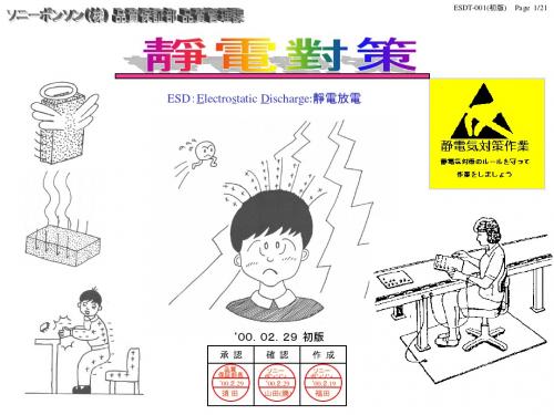
ESD:Electrostatic Discharge:靜電放電
‘00.02.29 初版
承 認
品質 保証部長
ESD静电防护基础知识(中英文版)

相信有大約25%的IC材料是因靜電(ESD)的影響而遭破壞
33
Definitions 定義
Electrical Over Stress(EOS)-The exposure of an item to a current or voltage beyond its maximum ratings.
After the invention of gun powder by the Chinese,it was no longer a curiosity for anyone manufacturing that product.
靜電現象一直存在於人類歷史中,以前則被認為是一種奇特的異象
Today, special precautions are taken by industries where static sparks could cause an explosion,e.g.., flour mills,hospital operating rooms,etc ..
11
MM
自動組裝之製造環境ESD 模型
電感
I (A)
Time (ns) 12
CDM
CDM Event 的來源
• 測試機台 • 自動插件 • IC的包裝 (Tube)
13
Definition 定義(1)
1. Conductive material - ESD protective material having a surface resistivity less than 1 x E5 ohms/square or a volume resistivity less than 1 x10E4 ohm-cm. 導體 - ESD保護物質其表面電阻系數小於 1x10E5 歐姆/單位面積或容積電阻係數小於 1 x 10E4 歐姆公分者.
S CIENTIFIC 高电流电磁漏电器实验用品说明书
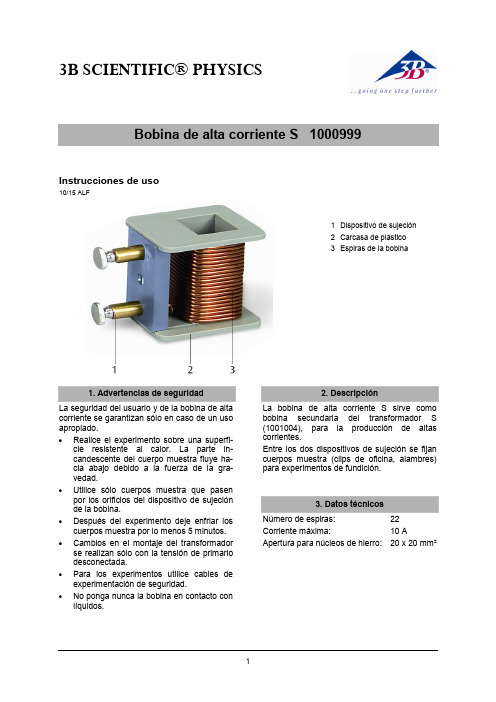
3B SCIENTIFIC® PHYSICS1Bobina de alta corriente S 1000999Instrucciones de uso10/15 ALF1 Dispositivo de sujeción2 Carcasa de plástico3 Espiras de la bobina1. Advertencias de seguridadLa seguridad del usuario y de la bobina de alta corriente se garantizan sólo en caso de un uso apropiado.∙ Realice el experimento sobre una superfi-cie resistente al calor. La parte in-candescente del cuerpo muestra fluye ha-cia abajo debido a la fuerza de la gra-vedad.∙ Utilice sólo cuerpos muestra que pasenpor los orificios del dispositivo de sujeción de la bobina.∙ Después del experimento deje enfriar loscuerpos muestra por lo menos 5 minutos. ∙ Cambios en el montaje del transformadorse realizan sólo con la tensión de primario desconectada.∙ Para los experimentos utilice cables deexperimentación de seguridad.∙ No ponga nunca la bobina en contacto conlíquidos.2. DescripciónLa bobina de alta corriente S sirve como bobina secundaria del transformador S (1001004), para la producción de altas corrientes.Entre los dos dispositivos de sujeción se fijan cuerpos muestra (clips de oficina, alambres) para experimentos de fundición.3. Datos técnicosNúmero de espiras: 22 Corriente máxima: 10 AApertura para núcleos de hierro: 20 x 20 mm²3B Scientific GmbH ▪ Rudorffweg 8 ▪ 21031 Hamburgo ▪ Alemania ▪ Se reservan modificaciones técnicas © Copyright 2015 3B Scientific GmbH4. ManejoPara la realización del experimento se requieren adicionalmente los siguientes aparatos:1 Fuente CA/CC 0 - 20 V, 0 - 5 A @230 V 1003562 o1 Fuente CA/CC 0 - 20 V, 0 - 5 A @115 V 1003561 1 Núcleo de transformador S 1001004 1 Bobina de transformador S1001000∙ Se ensambla el transformador como semuestra en la Fig. 1 y se coloca sobre una superficie resistente al calor. ∙ Se aprisiona el cuerpo muestra (alambre,clip de oficina) entre las dos partes del dispositivo de sujeción. ∙ La bobina primaria, en las tomas de 200espiras, se conecta en la salida de corriente alterna de la fuente de alimentación.∙ Se conecta la bobina de red y se ajustauna tensión entre 10 V y 20 V.Después de un corto tiempo el cuerpo muestra empieza a ponerse al rojo debido a la alta cor-riente y se funde.∙ Los restos del cuerpo muestra se dejanenfriar por lo menos unos 5 minutos y luego se desechan.10 - 20 VFig. 1 Montaje experimental。
ESD操作维护手册
ESD操作维护手册ESD控制面板操作维护手册ESD-01综述ESD控制面板设计为具有ESD控制回路,FSD(易熔关闭系统)控制回路以及3个液压控制接口。
面板上有液压控制接口的手动开/关。
ESD控制回路和FSD控制回路和液压控制接口的工作状态也显示在面板上。
面板空气源压力高低压感应阀供气压力易熔回路供气压力ESD按钮供气压力控制供气压力拔开/推关所有液控阀按-易熔回路充气按-ESD回路充气液压泵排出压力液控阀1压力液控阀2压力液控阀3压力控制面板的设置和操作程序概述1、确保现场所有的输入和输出都与面板的接头相连接。
现场的仪表空气供给3.5kg/sq.cm 应该通到流动管线高低压感应导阀管路。
面板仪表空气供给至少应为5.0kg/sq.cm ,显示在压力表DD-1上。
设置程序1、调节压力控制器JJ-1至3.5kg/sq.cm 。
压力表X-1会显示此控制压力的设置。
2、 ESD 控制回路充气按阀CC-2,为ESD 控制回路充气。
ESD 控制回路充气压力会显示在压力表X-3上。
3、 FSD 控制回路充气按阀CC-1,对FSD 控制回路充气。
FSD 控制回路充气压力会显示在压力表X-2上。
4、液压系统a 、检查并将液压油箱加液压油至液位计的最大刻度,如图中指定的位置。
b 、调节压力控制器JJ-2的输出压力至0。
c 、确保阀K-3是关闭的。
液压系统的所有的其他阀门都处于开启状态。
将液压泵LL-1空气供给压力调节器JJ-2旋转1/4转,液压泵LL-1开启,直到液压系统的液压压力增大到由泵输出压力和空气供给压力比率设定的压力值。
继续以不同的压力增量调高空气供给压力调节器的供给压力,使得每次系统的液压压力保持稳定(由泵停止为指示),直到达到要求的液压系统压力400kg/sq.cm 。
到液控阀1到液控阀2到液控阀3面板空气源空气供应到高低压感应阀到易熔回路到ESD 回路液压油罐泄放过滤器泄放面板呼吸器从高低压感应阀在加压过程中,注意检查液压系统管线接头可能出现的液压油泄露。
ESD测试作业指导书(中英文)
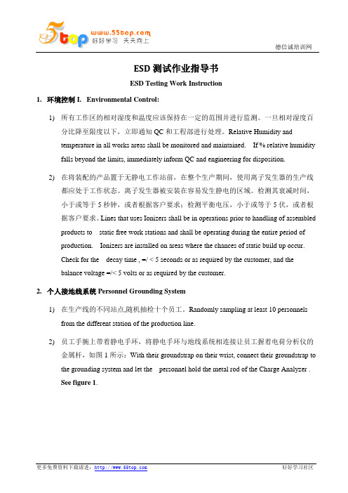
ESD测试作业指导书ESD Testing Work Instruction1.环境控制I. Environmental Control:1)所有工作区的相对湿度和温度应该保持在一定的范围并进行监测。
一旦相对湿度百分比降至限度以下,立即通知QC和工程部进行处理。
Relative Humidity andtemperature in all works areas shall be monitored and maintained. If % relative humidity falls beyond the limits, immediately inform QC and engineering for disposition.2)在将装配的产品置于无静电工作站前,在整个生产期间,使用离子发生器的生产线都应处于工作状态。
离子发生器被安装在容易发生静电的区域。
检测其衰减时间,小于或等于5秒钟,或者根据客户要求;检测平衡电压,小于或等于5伏,或者根据客户要求。
Lines that uses Ionizers shall be in operations prior to handling of assembled products to static free work stations and shall be operating during the entire period ofproduction. Ionizers are installed on areas where the chances of static build up occur.Check for the decay time , =/ < 5 seconds or as required by the customer, and thebalance voltage =/< 5 volts or as required by the customer.2.个人接地线系统Personnel Grounding System1)在生产线的不同站点,随机抽检十个员工。
ESD静电控制手册(ESD手册中英文)

ESD静电控制手册TABLE OF CONTENTS1. Purpose 目的2. Scope 范围3. Definition 定义4. Responsibility 职责5. Operation Content 作业内容5.1 ESD Control Program ESD 管制方案5.2 ESD Control Program Mgr or Coordinator ESD 管制方案经理或协调员5.3 Update 文件修改与更新5.4 ESD Control Operation ESD 管制作业5.4.1 ESD Protected Area ESD 保护区5.4.2 Training Requirement 培训要求5.4.3 ESD Test requirements ESD 测试要求5.4.4 ESD Grounding System ESD 接地系统5.4.5 ESD Floor Control ESD 地板管制5.4.6 ESD Garment & ESD Cap Control 静电衣服&静电帽管制5.4.7 ESD Shoe Control 静电鞋管制5.4.8 ESD Gloves& Finger Cots Control 静电手套&指套管制5.4.9 ESD wrist strap Control 静电手环管制5.4.10 Equipment ESD Control 设备ESD 管制5.4.11 Fixture& Tools Control 工治具管制5.4.12 Work Surface control 工作台管制5.4.13 ESD Marking ESD 标示5.4.14 ESD Packaging Material ESD 包装材料管制5.4.15 ESD Seating 静电座椅5.4.16 Soldering Iron Control 铬铁静电管制5.4.17 Air Ionizer Control 离子风机管制5.5 Sub-contractor control 外包商管制6.Reference 参考文件ESD Manual 静电控制手册1. Purpose 目的To prevent ESDS objects in manufacture, assembly, install, package, test, inspection,preservation, transport or other operation activities from damage, and protect electrical or electronic parts, assemblies and equipment so as to guarantee the product quality, so ESD protection.为防止静电敏感元器件在生产、组装,安装,包装,测试,检验、保存、運送及其他活动中受到静电之损害,保护电子器件,组件和设备,从而保证产品品质,特制订此手册,以提供本公司静电防护之最高指引.2. Scope 范围Applicable to all the related activities from ESD objects in DXC适用于公司所有ESD 敏感物件之相关活动作业3. Definition 定义3.1 ESD-E lectro S tatic D ischarge, the transfer or movement of charge between objects that are at different electrical potentials by direct contact or induced by electrostatic field.ESD-静电释放,是指通过直接接触或静电场感应的方式,在不同电势差物体间的电荷转移或移动。
ESD操作手册

东明项目WIZCON 操作手册Generall总则WIZCON is running on the PC an it has a communication to one or more PES´es。
WIZCON 是一个人击接口,它运行在PC上。
它可以与一个和多个ESD通信。
The communication is done by Modbus with Modbus codes over the RS485 interface or by OPC over a Ethernet module.通信既可以与Modbus,RS485通信也可以通过OPE在以太网来通信。
1 Install Wizcon安装WIZCON2 Create new project建立新的项目Start Wizcon by a click on the Wizcon icon.点击wizcon 标记,开始启动wizcond 的安装。
Before creating a project for a special application create a blank project in the offered path. 在建立一个项目之前,wizcon 要求在提供的路径下建立一个空白的项目。
Leave the blanc application immediately by clicking on this button. 点击这个按钮,立即离开空白的项目应用。
Now create you wanted application on the base of the blanc. 现在建立你想建立的项目,在空白的基础上。
Click on blank application.点击空白的应用。
Click OK点击OKFor the system tags it depends on your application, if you need them or not 对系统的位号。
ESD工作手册

ESD防护工作手册编辑:制作日期:目录第一章:静电基本知识1-1 平南事业所为什么要如火如荼地开展防静电工作?1-2.最常用的英文静电术语1-3. 静电定义1-4. 日常静电现象举例1-5. 静电是如何产生?1-6. 影响静电电压高低的重要因素1-7. 为什么不同物质之间的摩擦更容易产生静电?1-8. 静电人体感知1-9. 电子行业中的ESD破坏类型1-10. ESD破坏途径1-11. ESD破坏模式种类及其相应对策1-12. 敏感器件等级分类1-13. 静电防护控制技术依据1-14.常用防静电测试设备种类1-15.我司防静电执行基本方法第二章:防静电器材基本知识2-1.在国内静电防护学术界领域内,材料如何分类?2-2. 在实际应用当中,材料划分实践与理论又有何区别?2-3. 防静电材料为什么能防静电?2-4. 为什么说绝缘材料不能在防静电工作区内使用?2-5.为什么说金属导体不是最好的防静电材料?2-6. 哪一类材料是最理想的防静电材料?2-7. 防静电工衣、工帽、工鞋、手腕如何起防静电作用?静电又是如何排泄的?2-8.防静电地板如何起防静电作用?静电又是如何排泄的?2-9 .防静电工作台、工作椅子、地板如何起防静电作用?静电又是如何排泄的?2-10. 防静电周转容器、金属导体如何起防静电作用?静电又是如何排泄的?2-11.防静电包装袋种类和作用?2-12.简述离子风机的作用?其原理?2-13. 防静电剂分类和作用?2-14.防静电胶皮种类和结构2-15.防静电材料哪些类型为永久性材料?哪些类型是有一定使用寿命期材料?第三章:防静电工作区基本知识3-1.如何定防静电区域)边界呢?3-2. 防静电区域有那些基本标识?防静电标识的维护人员和张贴人员是谁?3-3.防静电工作区一级区域和二级区域如何去界定?3-4.防静电工作区一级区域和二级区域管理具体实施措施有何不同?3-6. 在防静电区域内,如果某机种或器件对静电不敏感,我们是否可以不按照防静电要求进行操作?3-7. 信华防静电工作区内的常见的静电源有哪些和分类?以及如何处理?3-8. 信华EPA内防静电器材材料与非防静电材料之间物品有哪些,以及如何处理?3-9. 防静电工作区地线如何接法?3-10. 防静电工作区设备如何接地?3-11. 我司有哪些具体相关的防静电措施,防静电一级区域和二级区域要求又有何不同?第四章:防静电工作区常见不良案例第一章:静电基本知识1-1 平南事业所为什么要如火如荼地开展防静电工作?因为平南事业所大部分产品为电子产品,其在加工过程中对静电的敏感度相当高,相当部分的元器件敏感度耐压值为100-500V 之间,而通常不做任何防静电措施的生产现场,其静电电压水平一般都在几百到上千伏以上,高的可达几十千伏,所以从产品的质量和可靠性,我们必须要做防静电工作。
迪尔·特斯莱·电磁烤鱼板用户手册说明书

Avance CollectionSmoke-less infrared heattechnologyMinimizes unpleasant smokeand greaseEasy to set up, Easy to cleanHD6371/94Delicious grilled food with virtually no smokethanks to advanced infrared heat technologyPhilips Indoor Smoke-less grill is a unique appliance that allows you to enjoy tasty,evenly browned grilled food all year round. The advanced infrared heat technologyensures up to 80% less smoke and minimal splattering.Makes grilling indoors a comfortable experienceAdvanced infrared heat technology for up to 80% less smokeEasy set-up means you can start grilling within 1 minuteEasy to clean detachable parts are also dishwasher-proofKeep your food warm with keep warm functionDelicious, evenly grilled food. Guaranteed.Constant heat for perfect browning without burningPowerful infrared heat sears the meat & preserves tendernessAll sides evenly grilled thanks to special heat reflectorsNon-stick ALU grid provides authentic BBQ grill marksVariety of healthy grilled foodLean grilling- excess fat is collected on XL grease trayFree recipe book with inspiring grill recipesHighlightsSmoke-less infrared technologyThe advanced Infrared technology and thespecial reflectors guide the heat towards the grid achieving delicious, evenly grilled food,while leaving the grease tray cool enough to minimize unpleasant smoke and greasesplattering. As fat and water content differ per food type, grilling some ingredients (beef and chicken) results in hardly any smoke, while with others (pork or lamb) there can be slightly more-yet much less than with current grills.Juicy and tender grilled foodThe powerful infrared heat sears the meat without burning it, while the inside remains tender and juicy.Non-stick aluminum gridThe robust die-cast aluminium grid allows for a perfectly grilled foodPerfectly browned, evenly cookedTo get a great browned piece of meat you need to cook it at temperatures above 300 F. Burning can occur when meat comes in contactwith 500 degrees F or more (or if you overcook it). Philips Smoke-less grill reaches temperature of 450 F that does not experience theoccasional drops of temperature like in theconventional grills. In addition, the ALU gridhelps achieve authentic BBQ grill marks on food.Special design of reflectorsWhen using conventional grills there arecontinuous temperature fluctuations that cause the grill to over shoot your set temperature and likely char your food. With the Philips Smoke-less indoor grill, there’s no need to adjust the temperature. The grill quickly heats up to a constant 446° F degrees- which is the perfect temperature for searing meat- and maintains that temperature throughout the entire cooking process. With one perfect temperature you will be able to grill different types of food all at once and achieve tasty, juicy and evenly browned results with minimal effort.Easy to cleanGrills and BBQs are hard to clean. However,thanks to the non-stick grid, the appliance takes less than a minute to be cleaned.Additionally, the detachable parts aredishwasher safe. Cleaning a grill has never been so easy.Lean GrillingFood is not cooked in its own grease and the fat is separated into the grease tray allowing for lean grilling.Easy set-upSimple to use, easy to install. The PhilipsSmoke-less Indoor grill consists of two parts: a grid and grease tray, which will take less than a minute to assemble. With minimal parts to set up, you will spend less time on assembly and more time on enjoying all the goodness of grilled food.Free recipe bookDelicious recipes, handy tips and tricks- allincluded in the free recipe book.IF DESIGN AWARDIF award-winning products and projects,concepts and more, selected by the top names in design.Each year, iF International Forum Design GmbH organizes one of the world's most celebrated and valued design competitions: the iF DESIGN AWARD. Recognized as a symbol of design excellence around the world, the iF DESIGN AWARD welcomes over 5,000submissions from 70 countries every year.SpecificationsGeneral specificationsProduct features: Cord storage, Dishwasher safe, Infrared Heat Technology, Non-slip feet, On/off switch T echnical specificationsPower: 1660 WVoltage: 120 VWeight and dimensionsWeight incl. packaging: 7,05 kgWeight of product: 5.6 kgDesignColor: Black© 2019 Koninklijke Philips N.V.All Rights reserved.Specifications are subject to change without notice. Trademarks are the property of Koninklijke Philips N.V. or their respective owners.Issue date 2019‑04‑16 Version: 10.1.1EAN: 00 07502 00525 75。
伊莱斯ESDB说明书英文版_
The grounding terminal must be grounded correctly; bad ground may cause electric shock or fire.
4. Notes for Operation
Before power on, please make sure the servo driver and servo motor have already been installed and fixed correctly, and the power voltage and wiring is right. Before using the driver, confirm the machine’s coupling and belt are separated, and set the driver’s parameter to suitable value. Test the servo motor to confirm it is operating correctly, and then connect to the load; otherwise it may cause machine damage and breakdown.
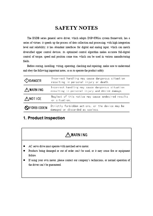
1. Product Inspection
AC servo drive must operate with matched servo motor. Products being damaged or out of order can’t be used, or it may cause fire or equipment failure. If using your own motor, please contact our company’s technicians, or normal operation of the driver can’t be guaranteed.
ESDS使用手册 英语版

»Prerequisites: All personnel work with ESDS equipment.
»人员要求:所有在工作中与ESDS器件有关的 人员
2020/2/29
经典PPT模版 欢迎下载
4
总 体 介 绍-- 课 程 大 纲
2
总 体 介 绍– 背景原因
»EASA要求
»FAR要求
»提高员工技能
»降低维修/维护成本
»行业标准技术更新
»定期重温
2020/2/29 课 程 大 纲
»Target Group: Personnel involved in line/hangar maintenance, electrical avionics workshop, material shipping and receiving.
护 措 施.
2020/2/29
经典PPT模版 欢迎下载
6
COU总RS体E C介AT绍A--L课OG程课大程纲大 纲
授课内容:
• GAMECO培训部编订的中英文教材.
• 维护手册二十章中与ESDS相关的内容.
• 有关ESDS的录相带
• ESDS实际范例
2020/2/29
经典PPT模版 欢迎下载
7
COU总RS体E C介AT绍A--L课OG程课大程纲大 纲
2020/2/29
14
静电的概念—静电表现及危害
Thus voltages of 12,000 to 35,000 volts can develop on a person.
Touching connector pins of computer units, a discharge path is formed through wiring and components.
Eaton Moeller MSC-DE DOL电动启动器说明书

Eaton 121741Eaton Moeller® series MSC-DE DOL starter, 380 V 400 V 415 V: 4 kW, Iq= 100 kA, Ir= 3 - 12 A, 230 V 50 Hz, 240 V 60 Hz, AC voltageGeneral specificationsEaton Moeller® series MSC-DE DOL starter1217414015081195510102 mm 198 mm 45 mm 0.724 kgVDE 0660 IEC/EN 60947-4-1Product NameCatalog Number EANProduct Length/Depth Product Height Product Width Product Weight Certifications9 AIs the panel builder's responsibility. The specifications for the switchgear must be observed.4 kW230 - 415 V AC0 A230 VMeets the product standard's requirements.Is the panel builder's responsibility. The specifications for the switchgear must be observed.DIN rail≤ 500 ms, main conducting paths, AC-4 cycle operationDoes not apply, since the entire switchgear needs to be evaluated.0 kW0 kWMeets the product standard's requirements.0 VShort-circuit release eaton-manual-motor-starters-device-msc-d-dol-starter-wiring-diagram.epseaton-manual-motor-starters-starter-msc-d-dol-starter-dimensions-002.epseaton-manual-motor-starters-mounting-msc-d-dol-starter-3d-drawing.eps eaton-manual-motor-starters-starter-msc-d-dol-starter-3d-drawing.epsDA-CE-ETN.MSC-DE-12-M9(230V50HZ)Simple, flexible and safe! Distribution system for motor-starter combinationsIL034038ZUDA-CS-msc_de_bg1DA-CD-msc_de_bg1DA-DC-00004108.pdfDA-DC-00004244.pdfRated operational current for specified heat dissipation (In) 10.11 Short-circuit ratingRated operational power at AC-3, 380/400 V, 50 Hz Rated operational voltageRated conditional short-circuit current, type 1, 480 Y/277 V Rated control supply voltage (Us) at AC, 50 Hz - min10.4 Clearances and creepage distances10.12 Electromagnetic compatibilityMounting methodCut-out periods - min10.2.5 LiftingRated power at 575 V, 60 Hz, 3-phaseRated power at 460 V, 60 Hz, 3-phase10.2.3.1 Verification of thermal stability of enclosures Rated control supply voltage (Us) at DC - minFitted with:Diagramas de cableado DibujoseCAD modelFolletosInstrucciones de instalación mCAD modelReportes de certificacionesCurrent flow times - min700 (Class 10) AC-4 cycle operation, Main conducting paths 500 (Class 5) AC-4 cycle operation, Main conducting paths Note: Going below the minimum current flow time can cause overheating of the load (motor).900 (Class 15) AC-4 cycle operation, Main conducting paths 1000 (Class 20) AC-4 cycle operation, Main conducting paths For all combinations with an SWD activation, you need not adhere to the minimum current flow times and minimum cut-out periods.Number of pilot lightsShort-circuit current rating (basic rating)125 A, max. CB, SCCR (UL/CSA)5 kA, SCCR (UL/CSA)125 A, max. Fuse, SCCR (UL/CSA)Rated control supply voltage (Us) at AC, 50 Hz - max230 VCoordination type110.8 Connections for external conductorsIs the panel builder's responsibility.Coordination class (IEC 60947-4-3)Class 1Rated conditional short-circuit current, type 1, 600 Y/347 V0 ARated conditional short-circuit current (Iq)100 kA at 380 – 400 VPower consumption, sealing, 50 Hz1.4 W, Dual-frequency coil in a cold state and 1.0 x Us, at 50 HzAmbient operating temperature - max55 °CRated operational power at AC-3, 220/230 V, 50 Hz2.2 kWConnection to SmartWire-DTNoNumber of command positionsStatic heat dissipation, non-current-dependent Pvs1.4 WElectrical connection type of main circuitScrew connectionElectrical connection type for auxiliary- and control-current circuit Screw connectionRated control supply voltage (Us) at DC - max0 V10.9.3 Impulse withstand voltageIs the panel builder's responsibility.Ambient operating temperature - min-25 °C10.6 Incorporation of switching devices and componentsDoes not apply, since the entire switchgear needs to be evaluated.10.5 Protection against electric shockDoes not apply, since the entire switchgear needs to be evaluated.ClassAdjustable10.13 Mechanical functionThe device meets the requirements, provided the information in the instruction leaflet (IL) is observed.10.2.6 Mechanical impactDoes not apply, since the entire switchgear needs to be evaluated.10.9.4 Testing of enclosures made of insulating materialIs the panel builder's responsibility.10.3 Degree of protection of assembliesDoes not apply, since the entire switchgear needs to be evaluated.Heat dissipation per pole, current-dependent Pvid0.7 WActuating voltage230 V 50 Hz240 V 60 HzVoltage typeACOverload release current setting - min3 AEquipment heat dissipation, current-dependent Pvid2.2 WHeat dissipation capacity Pdiss0 WRated operational current (Ie)8.5 ASuitable forAlso motors with efficiency class IE3Number of auxiliary contacts (normally closed contacts)10.2.3.2 Verification of resistance of insulating materials to normal heatMeets the product standard's requirements.10.2.3.3 Resist. of insul. mat. to abnormal heat/fire by internal elect. effectsMeets the product standard's requirements.Overload release current setting - max12 A10.9.2 Power-frequency electric strengthIs the panel builder's responsibility.Overvoltage categoryIIIDegree of protectionIP20NEMA OtherPollution degree3Rated control supply voltage (Us) at AC, 60 Hz - min0 V10.7 Internal electrical circuits and connectionsIs the panel builder's responsibility.Rated impulse withstand voltage (Uimp)6000 V ACConnectionScrew terminals10.10 Temperature riseThe panel builder is responsible for the temperature rise calculation. Eaton will provide heat dissipation data for the devices.Eaton Corporation plc Eaton House30 Pembroke Road Dublin 4, Ireland © 2023 Eaton. Todos los derechos reservados. Eaton is a registered trademark.All other trademarks areproperty of their respectiveowners./socialmediaTemperature compensated overload protection 0 A Starter with electronic trip unit Meets the product standard's requirements.Meets the product standard's requirements.Meets the product standard's requirements.186 A0 V9 A Direct starter1Max. 2000 mFunctionsRated conditional short-circuit current (Iq), type 2, 230 V Type10.2.2 Corrosion resistance10.2.4 Resistance to ultra-violet (UV) radiation 10.2.7 InscriptionsShort-circuit release (Irm) - max Rated control supply voltage (Us) at AC, 60 Hz - max Rated operational current (Ie) at AC-3, 380 V, 400 V, 415 V Model Number of auxiliary contacts (normally open contacts)Altitude。
电子清洁器说明书

Quick reference guide Dishwasher
Setting up Home Connect
9001843958 (030321) SPS4EMW61E
*9001843958*
How to use your appliance
1. Load the tableware.
tate freely.
Only clean tableware that is suitable for dish-
2. Add detergent.
Programme
1) Duration [h:min] 2) Energy [kWh] 3) Water [l]
Intensive 70°
1) 2:00 - 2:10 2) 1.050 - 1.150 3) 8.8 - 11.5
Auto 45-65°
1) 1:40 - 2:40 2) 0.650 - 1.050 3) 5.0 - 14.0
2. Pull up the lower spray arm to remove.
3. Check the outlet nozzles on the spray arms for blockages under running water and remove any foreign bodies.
Setting the water softening sys-
H02
tem
H03
1. Press .
- 1、下载文档前请自行甄别文档内容的完整性,平台不提供额外的编辑、内容补充、找答案等附加服务。
- 2、"仅部分预览"的文档,不可在线预览部分如存在完整性等问题,可反馈申请退款(可完整预览的文档不适用该条件!)。
- 3、如文档侵犯您的权益,请联系客服反馈,我们会尽快为您处理(人工客服工作时间:9:00-18:30)。
前言 Preface
ESDD 系列伺服驱动器是为驱动永磁同步伺服电机(PMSM)而开发的一款伺服驱动器。ESDD 系列 伺服驱动器容量范围涵盖广(额定电流 22 A ~ 3 0 0 A ), 是目前市场上性价比较高的中大功率伺服驱动器。
ESDD series servo driver is developed for driving the Permanent Magnet range of ESDD series servo driver is extensive in coverage (rated current 22A ~ 300 A). It is a medium and high power servo driver with higher cost-performance ratio on the existing market.
初次使用:Initial Use: 对于初次使用本产品的用户, 应先认真阅读本手册。若对一些功能及性能方面有所疑惑, 请咨询我公 司的技术支持人员, 以获得帮助, 对正确使用本产品有利。 The user who uses this product for the first time should firstly carefully read this manual. For any question on some function and performance aspects, please consult technical support personnel of our company to obtain help, which is favourable to correctly using this product. 由于本公司致力于伺服驱动器的不断改善, 因此所提供的资料如有变更, 恕不另行通知。 Because this company is devoted to constant improvement of the servo driver, the information provided will be subject to changes without further notice.
I
2、产品在运输过程中是否有破损现象;若发现有某种遗漏或损坏, 请速与本公司或您的供货商联系解决。 Whether there is any product damage in transport process. In the event of any omission or damage, please immediately contact this company or your supplier to solve it.
户操作手册及保修单。 Whether servo driver's model and rated value on the nameplate of this machine coincides with those on goods ordered by you and whether the machine, product qualification certificate, user manual and warranty bill are contained inside the case.
Ⅱ
目录 Table of Contents
前言 PREFACE ............................................................................................................................................................... I