最最最新MIC-800说明书
最新Mc800系列说明书
智能多媒体控制系统Intelligent Multimedia Control SystemMC800系列用户手册User’s Manual1第一章前言....................................................................................................3第二章系统硬件安装......................................................................................42-1、系统设备的接口说明 ......................................................................42-2、系统设备的连接 ..............................................................................82-3、电动屏幕的连接........................................................................................ 8第三章系统软件安装....................................................................................93-1、安装视频捕捉卡及其软件 ..............................................................93-2、安装电脑控制软件设置 .............................................................. 10第四章系统通讯协议................................................................................ 19第五章系统备份与恢复............................................................................ 24第六章常见问题........................................................................................ 256-1. 按控制面板“系统开”无法开机 ................................................... 256-2. 红外学习不成功或显示成功却不能遥控.................................... 266-3. 有些设备红外遥控不灵 ............................................................... 266-4. 投影机切换不灵 ........................................................................... 266-5. 关投影机出问题 ........................................................................... 272第一章前言本手册说明了您所使用的智能多媒体控制系统(IMCS)的硬件和软件的安装和功能设置。
GM-8003D对讲话筒调试说明书解读
桌面式IP对讲呼叫话筒说明书承蒙您选购本公司的网络广播产品,谨致谢意目录目录 (2)1安装须知 (3)2注意事项 (3)3产品描述 (4)4接口说明 (4)5安装调试 (5)6操作说明 (8)6.1终端配置 (8)6.2用户登录 (9)6.3功能选择 (9)6.4终端状态查看 (10)6.5拨号对讲与寻呼讲话 (10)6.6 对中心呼叫 (13)6.7节目点播 (14)6.8播放控制 (15)6.9退出登录 (16)7功能描述与技术参数 (16)8常见故障与维护 (17)8.1网络连接状态未连通现象 (17)8.2播放MP3时没有声音 (17)8.3播放时声音断续 (17)1安装须知•使用前请详读本须知。
•确实注意本手册中出现的安全符号及重要警告。
•建议您保留本手册作为日后参考之用。
常用安全符号和警告:本手册所示安全符号和警告是为了防止因操作不当而引起的人员伤害及财产损失。
请在使用本产品前详读本手册,务必明白各种安全符号及警告示意,以便知晓潜在危险。
如果使用不当将会引起人员之伤害及财产损失。
安装本产品时:•绝对不可将本产品暴露在室外淋雨及任何潮湿或易遇水处,以免引发触电或火灾等。
•使用本产品所规定之电压,如使用较高电压可能会引起触电或火灾。
•绝对不可修剪、扭曲、破损或更换机内电线。
•严禁在发热物体附近使用本产品,严禁将重物、包括机器本身置于机身电线上,以免引发触电或火灾。
•严禁在不稳定处安装或架设本产品,确保机器安装稳定牢固。
•绝对不可湿手插、拔电源插头,以免被电击伤或烧坏机器。
•在拔出插头时,确保用手握住插头往外拔,而不是拉电线。
使用有破损电线的机器可能会引起火灾或电击。
•移动机器时,请将电源插头事先拨出。
若将机器与电源插头一起搬动可能会引发火灾或电击。
•不可将机器的通风口盖住,否则会导致机器内部过热而发生火灾。
•避免将本产品安装在灰尘多、直接与阳光接触、有黑烟或蒸汽处,以防引起火灾或电击。
2注意事项如在使用中发现下述任何不正常状况,请立即将电源关闭,拔出电源插头,迅速与您最近的经销商联络。
PreSonus M80 八路麦克风预置器说明书

4
OVERVIEW
phase reverse switch allows the operator to avoid phase cancellation when identical microphones are used in close proximity to one another. The phase reverse switch also can compensate for different XLR connector hook-ups where pin connections have been inverted.
PreSonus Audio Electronics Inc. warrants this product to be free of defects in material and workmanship for a period of one year from the date of original retail purchase. This warranty is enforceable only by the original retail purchaser. To be protected by this warranty, the purchaser must complete and return the enclosed warranty card within 14 days of purchase. During the warranty period PreSonus shall, at its sole and absolute option, either repair or replace, free of charge, any product that proves to be defective on inspection by PreSonus or its authorized service representative. To obtain warranty service, the purchaser must first call or write PreSonus at the address and telephone number printed below to obtain a Return Authorization Number and instructions of where to return the unit for service. All inquiries must be accompanied by a description of the problem. All authorized returns must be sent to the PreSonus repair facility postage prepaid, insured and properly packaged. PreSonus reserves the right to update any unit returned for repair. PreSonus reserves the right to change or improve the design of the product at any time without prior notice. This warranty does not cover claims for damage due to abuse, neglect, alteration or attempted repair by unauthorized personnel, and is limited to failures arising during normal use that are due to defects in material or workmanship in the product. Any implied warranties, including implied warranties of merchantability and fitness for a particular purpose, are limited in duration to the length of this limited warranty. Some states do not allow limitations on how long an implied warranty lasts, so the above limitation may not apply to you. In no event will PreSonus be liable for incidental, consequential or other damages resulting from the breach of any express or implied warranty, including, among other things, damage to property, damage based on inconvenience or on loss of use of the product, and, to the extent permitted by law, damages for personal injury. Some states do not allow the exclusion of limitation of incidental or consequential damages, so the above limitation or exclusion may not apply to you. This warranty gives you specific legal rights, and you may also have other rights, which vary form state to state. This warranty only applies to products sold and used in the United States of America. For warranty information in all other countries please refer to your local distributor.
K-800话筒啸叫抑制器说明书

K-800话筒啸叫抑制器说明书一、K-800话筒啸叫抑制器KTV因为房间小,声学结构复杂,建声环境差,很容易发生啸叫问题(飞麦),我们经常遇到话筒音量只能很小,开大一点就啸叫,有的工程师采用压小高音、低音,减小混响等,往往只是委曲求全,这样使演唱者唱的辛苦而无法尽兴,就要求DJ调节话筒音量和功放;而且啸叫发生时很容易烧坏音箱和功放,造成DJ忙的不可开交,老板焦头烂额。
K-800话筒啸叫抑制器是采用数字移频技术、音乐均衡技术和噪声门技术的新一代KTV 反馈抑制设备,音质高保真,它能够有效的抑制扩声啸叫,彻底解决了长期以来困扰人们的KTV包房扩音声反馈的难题,提高传声增益6-12dB,话筒的拾音距离提高了,唱歌不用堵在嘴边,卫生又舒适,使演唱者可以尽兴演唱,彻底解决了包房管理麻烦等缺陷,设备经安装调试后,打开电源即用,无需专人管理。
本产品采用进口贴片器件、波峰焊接,严格的工艺、检验流程保证了一流的产品品质。
适用范围:10-200平方米的包房、HI房等场所。
1.1系统特点:1、设备傻瓜性:本设备使用简单,连接方便,无须专业工程人员。
2、设计科学性:本系统各设备在设计中追求科学和先进,其中话筒长于语言的高保真拾音,重于语音的清晰还原。
3、工作稳定性:电路的简洁,连接的简单,使得系统工作的可靠性提高,故障发生几率降低。
4、投资经济性:功能集中,设备组件配备精良,加上微电脑技术普及、新工艺的采用,成本有效地控制,系统性价比高,任何场合都用的起。
1.2产品功能:➢彻底解决KTV场合啸叫问题(飞麦)。
➢提升话筒增益6-12DB,唱歌不用堵在嘴上➢提供麦克风均衡参数调整➢提供麦克风高切低切调整➢可驳接四支话筒输入,可接无线话筒➢1.3产品特点:1.内置高保真数字移频器,具备至强啸叫抑制器内核。
2.内置六段衰减式均衡器电路,可对啸叫区域频段进行适当衰减,防啸叫效果显著。
3.内置高低切线路,可根据情况限制音响频宽,从而减少了反馈的可能。
SM800型酶标仪用户手册说明书

SM800酶标仪说明书企业名称:上海永创医疗器械有限公司注册地址:上海市松江区车墩镇北松公路7459号7幢2层生产地址:上海市松江区车墩镇北松公路7459号7幢2层联系电话:86-21-6774257867741937传真:86-21-67741776网址:邮编:201611上海永创医疗器械有限公司发布目录目录 0质量保证 (3)重要说明 (4)1.简介 (6)1.1仪器结构 (6)1.2光路系统 (7)1.3规格和参数 (8)2.开箱与安装 (9)2.1开箱 (9)2.2安装 (9)2.3初次开机 (9)2.4术语介绍 (9)3.软件 (11)3.1初始化 (11)3.2登录 (11)3.3主窗体 (11)3.3.1工具栏 (12)3.3.2快捷键 (13)3.4系统菜单 (13)3.4.1用户管理 (13)3.4.2切换用户 (13)3.4.3系统选项 (14)3.4.4退出 (14)3.5项目菜单 (14)3.5.1测试项目设置 (15)3.5.2项目编组 (20)3.5.3标准品管理 (20)3.6质控菜单 (22)3.6.1质控管理 (22)3.6.2质控设置 (23)3.6.3质控数据 (24)3.6.4质控图谱 (25)3.7病人菜单 (25)3.7.1病人信息 (26)3.7.2用户字典 (27)3.7.3输入偏好 (27)3.7.4打印报告 (29)3.8布板 (30)3.9分析菜单 (31)3.9.1运行分析 (31)3.9.2停止 (36)3.9.3停止报警 (36)3.9.4简单测试 (36)3.9.5结果/布板 (37)3.10报告菜单 (37)3.10.1病人综合报告 (37)3.10.2整板测试报告 (38)3.10.3简单测试报告 (39)3.11工具菜单 (39)3.11.1通讯设置 (39)3.11.2复位 (40)3.11.3波长设置 (40)3.11.4仪器维护 (41)3.11.5导出分析结果 (41)3.12帮助菜单 (41)3.12.1技术支持 (42)3.12.2关于 (42)4.仪器维护 (43)4.1日常清洁和消毒 (43)4.2触摸屏日常维护 (43)4.3安装光源 (43)4.4更换保险丝 (44)5.故障排除 (45)6.装箱清单 (46)6.1附件 (46)6.2随机文件 (46)质量保证用途:本产品供临床检验和医学科研单位进行酶联免疫测定。
MAX800说明书V8.3

MAX800简明使用说明书一.简介:摘机后拨 ***嘟进入设置状态,如需验证系统密码再按 *#四位密码,每设置一步后,一声长“嘟”提示设置成功,两声短“嘟嘟”表示出错。
(**# 进入设置,成功拨*,出错拨#,适合用设备快速设置)以下N为卡序号1-8,B为1或0开关某项功能**9**拨号器清除或恢复出厂设置*9*N**接入码*。
** IP卡设置*8N*XY* 卡检测语音属性*7*N*区号*/# 开通区号设置,默认全开通*6*N# 结束码# 、*6*N* 不加结束码,默认加#*5*N*ABCDEF* 语音后分段延时,默认不延时*4*N** 选择优先卡,最后设置的卡默认为优先卡*3*N*旧密码*新密码* 设置、修改卡使用密码*2*N** 删除IP卡*0N*XY* 将N号卡的对方号码从第X位后起删除Y位**4*xy* 设置拨号速度,默认55,对应75ms/75ms**3*密码* 设置系统密码**5M*xxxx*x…**设置字头**20B* 使用IP拨打后发提示“嘟”音,默认关闭**21M* 延时M秒加 #,默认2秒**22M* 通话后限制继续拨号。
默认关闭**22XY* 查余额后XY秒静音。
默认关闭**23B* B=1关闭0开头区号表,完全按字头启动/国外用**24M* ## 变为一个 * 拨出。
默认0关闭**27M* M=0-# 铃声检测,防断线功能。
无默认值**28MY* M :*后首位拨号加长,Y对方号首位加长,默认31 **29M* M=0-7,语音灵敏度。
默认3*1*N* MxxxMxx….** 专家模式,在每一个*后分别控制语音、延时、插拨号码等等;二.IP卡的输入:1、*9*卡序号**接入号*语言选择*PIN1*PIN2**1)“卡序号”是卡存放在拨号器内8个位置,可为1--82)“接入号”是进入系统的系统号,如200,1933)“语言选择”一般带PIN码的付费卡都可能有提示语言选择,没有的可以不设置{提示语言选择*};4)PIN码有一个或多个,没有的不设置。
800 无线耳机用户手册说明书

800O W N E R’S M A N U A LINTRODUCTION (1)WHAT’S IN THE BOX (2)PRODUCT OVERVIEW (3)Controls on headset (3)Controls on 2.4G USB wireless dongle (5)Controls on 3.5mm audio cable (6)GETTING STARTED (7)Charging your headset (7)Wearing your headset (8)Power on (9)First-time setup (for PC only) (9)USING YOUR HEADSET (11)With 3.5mm audio connection (11)With 2.4G wireless connection (12)With Bluetooth (secondary connection) (14)PRODUCT SPECIFICATIONS (16)TROUBLESHOOTING (17)LICENSE (19)Congratulations on your purchase! This manual includes information on the J BL QUANTUM800 gaming headset. We encourage you to take a few minutes to read this manual, which describes the product and includes step-by-step instructions to help you to set up and get started. Read and understand all the safety instructions before using your product.If you have any questions about this product or its operation, please contact your retailer or customer service, or visit us at 010*******0601 JBL QUANTUM800 headset02 USB charging cable (USB-A to USB-C)03 3.5mm audio cable04 2.4G USB wireless dongle05 QSG, warranty card and safety sheet06 Windshield foam for boom microphoneControls on headset01 ANC* / TalkThru** LED• Lights up when the ANC feature is enabled.• Flashes quickly when the TalkThru feature is enabled.02 button• Press briefly to turn ANC on or off.• Hold for more than 2 seconds to turn TalkThru on or off.03 / dial• Balances the chat volume in relation to the game audio volume.04 Volume +/- dial• Adjusts headset volume.05 Detachable windshield foam06 Mic mute / unmute LED• Lights up when the microphone is muted.07 button• Press to mute or unmute the microphone.• Hold for more than 5 seconds to turn the RGB light on or off.08 Charging LED• Indicates the charging and battery status.09 3.5mm audio jack10 USB-C port11 Voice focus boom microphone• Flip up to mute, or flip down to unmute the microphone.12 button• Hold for more than 2 seconds to enter Bluetooth pairing mode.13 slider• Slide upwards / downwards to power on / off the headset.• Slide upwards and hold for more than 5 seconds to enter 2.4G pairing mode.14 Status LED (Power / 2.4G / Bluetooth)15 RGB Lighting Zones16 Flat-fold ear cup* ANC (Active Noise Cancelling): Experience total immersion while gaming by suppressing the outside noise.** TalkThru: In TalkThru mode, you can hold natural conversations without removing your headset.Controls on 2.4G USB wireless dongle01 CONNECT button• Hold for more than 5 seconds to enter 2.4G wireless pairing mode.02 LED• Indicates the status of 2.4G wireless connection.Controls on 3.5mm audio cable01 slider• Slide to mute or unmute the microphone in 3.5mm audio connection.02 Volume dial• Adjusts headset volume in 3.5mm audio connection.Charging your headsetBefore use, fully charge your headset through the supplied USB-A to USB-C charging cable.TIPS:• It takes approximately 2 hours to fully charge the headset.• You can also charge your headset through a USB-C to USB-C charging cable (not supplied).• The headset cannot be powered on when being charged.Wearing your headset1. Put the side marked L onto your left ear and the side marked R onto your right ear.2. Adjust the earpads and headband for a comfortable fit.3. Adjust the microphone as necessary.Power on• Slide the power switch upwards to power on the headset.• Slide downwards to power off.The status LED glows solid white upon powering on.First-time setup (for PC only)Download from /engine to gain full access to features on your J BL Quantum headset - from headset calibration to adjusting 3D audio to suit your hearing, from creating customized RGB lighting effects to determining how the boom microphone side-tone works.Software requirementsPlatform: Windows 7 / Windows 10 (64 bit) only500MB of free hard drive space for installationTIP:• QuantumSURROUND and DTS Headphone:X V2.0 available on Windows only.Software installation required.1. Connect the headset to your PC via2.4G USB wireless connection (See “With 2.4Gwireless connection”).2. Go to “Sound Settings” -> “Sound Control Panel”.3. Under “Playback” highlight “JBL QUANTUM800 GAME” and select “Set Default”-> “Default Device”.4. Highlight “JBL QUANTUM800 CHAT“ and select “Set Default” -> “DefaultCommunication Device”.5. Under “Recording” highlight “JBL QUANTUM800 CHAT” and select “SetDefault” -> “Default Device”.6. In your chat application select “JBL QUANTUM800 CHAT” as the default audiodevice.7. Follow the onscreen instructions to personalize your sound settings.With 3.5mm audio connection1. Connect the black connector to your headset.2. Connect the orange connector to the3.5mm headphone jack on your PC, Mac,mobile or gaming console device.Basic operationNOTE:• The mic mute / unmute LED, button, / dial and RGB Lighting Zones on the headset do not work in 3.5mm audio connection.With 2.4G wireless connection1. Plug the2.4G USB wireless dongle into a USB-A port on your PC, Mac or PS4.2. Power on the headset. It will pair and connect with the dongle automatically. Basic operationTo pair manually1. On the headset, slide the power switch upwards and hold for more than 5 secondsuntil the status LED flashes white.2. On the 2.4G USB wireless dongle, hold CONNECT for more than 5 seconds untilthe LED flashes white quickly.Both LEDs on the headset and dongle turn solid white after successful connection.TIPS:• The headset turns off automatically after 10 minutes of inactivity.• The LED enters connecting mode (flashing slowly) after disconnection from the headset.• Compatibility with all USB-A ports is not guaranteed.With Bluetooth (secondary connection)With this function, you can connect your mobile phone to the headset while playing games, without worrying about missing important calls.1. Hold on the headset for more than 2 seconds.The status LED flashes quickly (pairing).2. Enable Bluetooth on your mobile phone and choose “JBL Quantum800” from“Devices”.The status LED flashes slowly (connecting), and then turns solid blue (connected).Control calls×1×2When there is an incoming call:• Press once to answer.• Press twice to reject.During a call:• Press once to hang up.TIP:• Use volume controls on your Bluetooth connected device to adjust volume.• Driver size: 50 mm Dynamic drivers• Frequency response (Passive): 20 Hz - 40 kHz• Frequency response (Active): 20 Hz - 20 kHz• Microphone frequency response: 100 Hz -10 kHz• Max input power 30 mW• Sensitivity: 95 dB SPL @1 kHz / 1 mW• Maximum SPL: 93 dB• Microphone sensitivity: -40 dBV @1 kHz / Pa• Impedance: 32 ohm• 2.4G Wireless transmitter power: <0 dBm• 2.4G Wireless modulation: π/4-DQPSK• 2.4G Wireless carrier frequency: 2403.35 MHz - 2479.35 MHz• Bluetooth transmitted power: <9 dBm• Bluetooth transmitted modulation: GFSK, π/4 DQPSK, 8DPSK• Bluetooth frequency: 2.402 GHz - 2.480 GHz• Bluetooth profile version: A2DP 1.3, HFP 1.6• Bluetooth version: V5.0• Battery type: Li-ion battery (3.7 V / 1300 mAh)• Power supply: 5 V 2 A• Charging time: 2 hrs• Music play time with RGB lighting off: 14 hrs• Microphone pickup pattern: Unidirectional• Weight: 410 gNOTE:• Technical specifications are subject to change without prior notice.If you have problems using this product, check the following points before you request service.No power• The headset turns off automatically after 10 minutes of inactivity. Power on the headset again.• Recharge the headset (see “Charging your headset”).2.4G pairing failed between headset and 2.4G USB wireless dongle • Move the headset closer to the dongle. If the issue remains, pair the headset with the dongle again manually (see “To pair manually”).Bluetooth pairing failed• Make sure you have enabled Bluetooth feature on the device to be connected with the headset.• Move the device closer to the headset.• The headset is connected to another device through Bluetooth. Disconnect the other device, then repeat the pairing procedures. (see “With Bluetooth (secondary connection)”).No sound or poor sound• Make sure you have chosen JBL QUANTUM800GAME as the default device in the game sound settings of your PC, Mac or gaming console device.• Adjust volume on your PC, Mac or gaming console device.• Check game chat balance on PC if you are only playing game or chat audio.• Check that ANC is enabled while TalkThru is disabled.• You may experience obvious sound quality degradation when using the headset near a USB 3.0 enabled device. This is not a malfunction. Use an extension USB dock instead to keep the dongle as far from the USB 3.0 port as possible.In 2.4G wireless connection:• Make sure the headset and 2.4G wireless dongle are paired and connected successfully.• The USB-A ports on some gaming console devices may be incompatible with JBL QUANTUM800. This is not a malfunction.In 3.5mm audio connection:• Make sure the 3.5mm audio cable is connected securely.In Bluetooth connection:• The volume control on the headset does not work for the Bluetooth connected device. This is not a malfunction.• Keep away from sources of radio interference such as microwaves or wireless routers.My voice cannot be heard by my teammates• Make sure you have chosen JBL QUANTUM800CHAT as the default device in the chat sound settings of your PC, Mac or gaming console device.• Make sure the microphone is not muted.I can’t hear myself when I’m talking• Enable sidetone via to hear yourself clearly over game audio. ANC/TalkThru will be disabled when sidetone is enabled.The Bluetooth® word mark and logos are registered trademarks owned by Bluetooth SIG, Inc. and any use of such marks by HARMAN International Industries, Incorporated is under license. Other trademarks and trade names are those of their respective owners.- 19 -HP_JBL_Q800_OM_V8。
MIC-800系列智能气体检测报警仪说明书

MIC-800系列智能气体检测报警仪操作说明1.1按键定义:本机共设三个按键,⊙键、↑键、↓键(从左到右顺序),⊙键为电源开关并起确认功能,↑键为移位键,↓键起翻页及数字加减的作用。
1.2开机方法:长按⊙键5秒钟不放,到了5秒钟后自动开机,开机以后显示的画面依次为:气体名称、最大量程及单位和电量,2秒钟后开始显示预热倒计时120秒,如果不想等待,按一下⊙键直接进入正常测量界面,左下角显示气体种类,此时振动马达及蜂鸣器、指示灯都报警1次表示正常启动,如果电量不足或者检测不到传感器,则一直报警下去,此时如果按一下⊙键起消音作用,声音及振动马达、指示灯都停止工作,但是显示屏上“ALARM”字样仍在闪烁,如果是电量不足,电量图标闪烁,如果是检测不到传感器,显示“FAULT”字样,此时再按一下⊙键,声音及振动马达、指示灯继续工作。
如果仪器是泵吸式,屏幕上就会显示泵的图标,并且一直在旋转,如果没有泵就不显示这个图标。
2菜单设置密码设置:依次按⊙键、↑键、↓键,在2秒钟内完成才有效菜单定义:Z、S、FS、AL、AH、CER、DEFA、OUT 2.1零点校准Z如果传感器出现零点漂移过大,需要进行零点校正。
如图1所示。
零点设置菜单默认为“N”,如图2所示,需要进行是否操作的确认。
如果确认要校准零点,在零点设置菜单通过↓键修改为“Y”,如图3所示。
按⊙键确认进行零点校准,如果校准成功,左下角出现“YES”字样,如图4所示。
如果校准不成功,左下角出现“NO”字样,如图5所示。
2.2目标点校准S如果传感器使用时间过长,需要进行灵敏度校正,通过↓键选到“S”选项,按一下⊙键进行修改,如图6所示。
目标点浓度设置菜单默认为“N”,如图7所示,需要进行是否操作的默认。
如果确认要校准目标点,在目标点设置菜单通过↓键修改为“Y”,如图8所示。
按⊙键确认进行目标点校准,如果校准成功,左下角出现“YES”字样,并且数值变为在菜单“CER”里设置好的值,如图9所示如果校准不成功,左下角出现“NO”字样,如图10所示。
最低抑菌浓度(MIC)测定

word附件3.4最低抑菌浓度(MIC)测定1.菌悬液的制备刮取18~20小时的培养物,在管壁上充分研磨后混悬于1ml缓冲液中,借助比浊仪,调菌悬液浓度至104/ml,于1小时用多点接种仪接种(放置室温应大于25℃)。
2.MIC测定(1)抗菌药物储存液制备⏹抗菌药物称量及配制:根据各抗菌药物的纯度称取,以目前所用抗菌药物为例。
抗菌素纯度称量(mg)加溶剂(ml)储存液浓度(μg/ml)四环素100% 3.2 1 3200大观霉素63.4% 40.38 1 25600头孢曲松81.5% 2.45 1 2000环丙沙星84.4 3.8 1 3200⏹分装与保存:每管200μl,-70℃可保存一年。
(2)抗菌药物工作液制备青霉素:四环素:大观霉素:头孢曲松:环丙沙星:(3)抗菌药物梯度培养皿的制备⏹培养皿编号:按各抗菌药物浓度编号。
⏹将配制好的各抗菌药物工作液150μl加到各培养皿中,与15ml 50℃预温的培养基充分混匀,平放在超净台,半开培养皿盖至培养基凝固后,用塑料袋密封保存于4℃冰箱。
(4)菌悬液接种与培养⏹多头接种针以及菌液板用高压法灭菌处理,其他配件用酒精消毒处理;使用前必须确认完全烘干。
⏹按照仪器要求将菌悬液接种于各抗菌药物梯度培养皿,接种菌后置超净台直至菌悬液渗入。
⏹置35℃~36℃、5%~10% CO2一定湿度的环境中培养。
⏹记录放置时间。
⏹培养18~24小时观察结果。
(5)结果判读⏹观察细菌生长情况:-记录结果读取时间。
-在适宜的光线下,观察对照培养皿的菌落生长情况,并对所有菌株进行初步鉴定(涂片染色和氧化酶试验)。
-比较观察对照平皿和抗菌药物平皿,进行判读:接种点有1个以上菌落或呈菌苔状为生长;接种点无任何菌落或呈薄雾印迹为无生长。
⏹MIC判读与记录:-MIC是指抗菌药物能够抑制细菌生长的最小抑菌药物浓度,表示单位为 g/ml 。
-记录各抗菌药物浓度平皿上细菌生长情况,在《WHO参考菌株及MIC 实验结果记录表》用(+)表示生长,(-)表示无生长。
楼宇对讲系统数字室内机使用手册说明书

产品型号:生产/经销商:楼宇对讲系统数字室内机使用手册欢迎选用我公司的楼宇对讲产品!本产品采用当今最先进的电子通信技术设计,以优良的SMT 工艺生产,经过严格的质量保证体系的测试与检验,具有高集成度、高可靠性、高性价比等特点,为值得信赖的安防对讲产品。
电源电压要求为直流12V,不可过高,或极性接反设备内含敏感电子元器件,需注意防潮、防水、防高温等设备包含液晶显示面板,不可用尖物或大力压碰装箱清单(表中配件可能根据型号不同而有所增或减)序号附件名称数量备注1主机1台2挂件(含配套螺丝)1个可能另行包装3配线1套电源线:2PIN 线x 1安防线:10PIN 线x 14说明书1本5合格证1张产品外观、尺寸、功能及界面与实物可能有所不同,以实物为准!一、产品介绍1.产品外观(产品外观、尺寸、功能及界面与实物可能有所不同,以实物为准)①②③④⑤⑥显示屏电源灯信息灯功能键喇叭MIC2.主界面(界面有多种风格,但功能基本一致,具体以实物为准)界面风格一:图标及功能说明:a.界面中央显示当前日期和当前时间,中央下方可对家居安防的安防模式进行修改。
b.界面右上方的二个图标:分别为“管理中心”和“视频监控”快捷键。
①②③④⑤⑥c.界面左上方图标:进入导航界面。
d.导航界面中,点击相应的图标可进入到对应的功能界面,执行相应的操作。
按右上角的图标即可返回主界面。
界面风格二:图标及功能说明:a.点击主界面中间对应的功能图标,系统可进入或执行相应的操作;b.点击界面右上方的四个快捷图标,可直接进入对应的快捷功能。
c.界面右下角分别是日期显示、时间显示和联网状态显示。
日期和时间显示在联网时为当前日期和时间,无联网时均显示“联网中…”。
联网状态显示第一个为门口机,第二个为管理中心,第三个为网络状态,正常连接为绿色,无连接网络或联网失败时为灰色。
二、通话对讲1.门口机呼入对讲:门口机呼入时,室内机自动弹出呼入视频界面,并同时振铃。
TELIKOU FT-800v2.3 内部通话主机 使用手册说明书

TELIKOU®内部通话系统FT-800四线制八通道内部通话主机使用手册©版权所有TELIKOU®产品使用说明书随时可能修改,恕不另行通知。
目录一、概述二、特点三、基本操作1、面板麦克风插孔(Panel)2、耳麦插孔(Headset)3、麦克风选择开关(Mic Select)4、音量调节5、通道开关6、通话指示灯7、节目(背景)音控制开关(Program Feed)8、节目(背景)音状态指示灯9、节目(背景)音电平调节(Program Level)10、电源开关及电源指示灯(Power LED)11、面板喇叭12、广播按键(ANN.)13、广播指示灯14、群呼按键(All)15、监听指示灯(Listen)16、节目(背景)音音量调节(Program Listen)17、面板麦克风增益调节(Panel Mic Gain)18、电源插座19、1-4通道泰丽信号接入口(1-4Tally In)20、四线制通道接口21、通道输入电平调节(Input)22、节目(背景)音输入口(Prog.In)23、广播输出口(ANN.Out)24、5-8通道泰丽信号接入口(5-8Tally In)四、连接CCU五、常见故障现象及排除方法六、技术指标一、概述感谢您选用了TELIKOU通话系列产品。
FT-800是一款四线制通话设备。
既可以连接CCU设备,也可以连接支持带TALLY功能的BK-104通话腰包。
该设备适用于电视台、通信指挥中心、电视转播车、演出现场及工程试验场等需要通讯联络的场合,尤其适合在较强电磁干扰的环境下使用。
本系统有线连接,不受外界辐射干扰影响,性能稳定可靠,配置灵活,全双工通讯,通话声音清晰宏亮、操作简单、抗噪声强。
二、特点●独特的抑制啸叫电路设计●广播输出●可控的背景音输入●8个支持TALLY灯工作的通道●电源短路自动保护和短路指示三、基本操作1、面板麦克风插孔(Panel)该插孔配接专用的ø6.35mm非平衡输出麦克风。
SE-800说明书
输出与监视器您所使用的 SE-800 设定与应用场合,将决定以何种视讯与音讯装置连接至输出。
如需范例说明,请参阅第 16 页的〈范例应用〉。
虽然 SE-800 的所有输出且有极佳的质量,但请记住,若以递渐方式排列各种格式的视讯质量,则为:SDI (序列数位)、Y.U.V.(模拟色差)、DV 、Y/C (S 视讯)与复合。
音讯输出属于 Line 等级,适合用于连接如扩大器、VCR 或视讯投影机。
监控系统的重要性不需要我们多说。
如果有什么在讯号路径最后阶段(即主输出)听起来或看起来不对,而且如果您可以精确指出讯号路径的问题所在,就能轻易修正问题。
如果可以监控每一个输入频道的视讯与主输出,将使某些设定大幅受益。
由于前面板的头戴耳机控件目,高质量的头戴耳机让您不需复杂的中间步骤,即可以监听音讯,而且获得的效果比扩大器或喇叭更加精准。
建议您同时采用这两种监听方式,而且透过视讯监视器的喇叭的听取音效,也是很好的办法。
更不用说,如果要输出至录音座,则应该也可以轻松监听装置的输出。
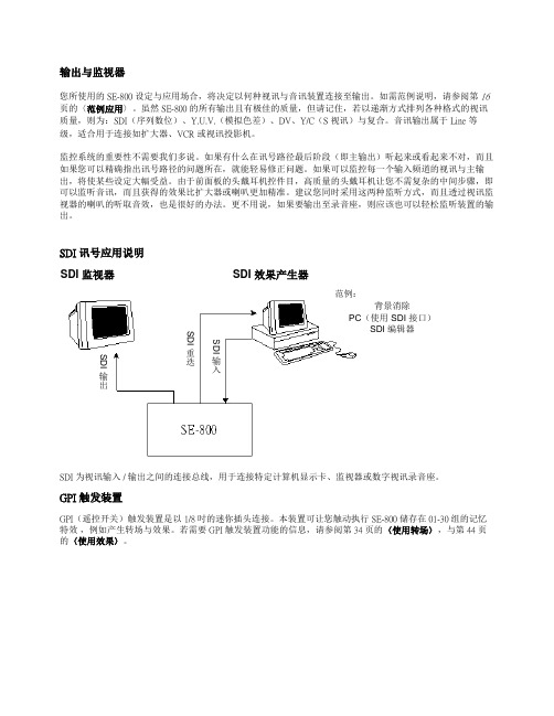
SDI 讯号应用说明SDI 为视讯输入 / 输出之间的连接总线,用于连接特定计算机显示卡、监视器或数字视讯录音座。
GPI 触发装置GPI (遥控开关)触发装置是以 1/8 吋的迷你插头连接。
本装置可让您触动执行 SE-800储存在01-30组的记忆特效 ,例如产生转场与效果。
若需要 GPI 触发装置功能的信息,请参阅第 34 页的〈使用转场〉,与第 44 页的〈使用效果〉。
SDI 监视器SDI 效果产生器SDI输出SDI重迭SDI输入现场表演应用:俱乐部的 VJ/说明会/表演活动…..图标上的文字:这个图示表示俱乐部 VJ 现场活动架设一种方式,也可调整适用于任何表演活动,例如演讲 / 说明会、混合媒体表演,甚至是现场音乐录像带制作。
此处将假设有多个音讯与视讯输入、观众观赏屏幕以及混音同步录制。
如图标连接录像机、输入及监视器装置。
请您:开启所有外围设备的电源,然后再开启 SE-800 的计算机。
Nady SCM 800用户手册说明书

Your SCM 800 microphone was carefully packed at the factory, and the shipping carton that was designed toprotect the unit during shipping. Please retain this container for subsequent transport and in the highly unlikely event that you ever need to return your microphone for servicing. The optional SMCC-2 aluminum carrying case is highly recommended for the most convenient and safe transport or permanent storage. It has roomy compartments for yourSCM 800 microphone and all available accessories, plus XLR cables.Congratulations on purchasing a Nady SCM 800 FET Condenser Microphone. These superior microphones are perfect for recording studio vocals, acoustic instruments, orchestras and choral groups, ambient instrument audio,and many live sound applications. Powerful and versatile, the SCM 800 microphones meet the stringent requirements of even the most demanding digital recording and live broadcasting applications.UNPACKING, INSPECTION, STORAGE AND TRANSPORTSCM 800 microphone User guide Warranty card 48V phantom power supply (SMPS-1)Aluminum flight case (SMCC-2)Shockmount (SSM-3)Foam windscreen (FW-2)STANDARD ITEMS SUPPLIED OPTIONAL ACCESSORIESFEATURESThis user guide covers the operation of the SCM 800 microphone and the available optional accessories.To take full advantage of the superb features of your microphone, and to enjoy long and trouble-free use, please read this user's guide carefully.• Perfect for all recording and broadcasting applications—featuring large-diaphragm true condenser design,transformerless low-noise/high-dynamic-range output, high SPL capacity, cardioid polar pattern pickup, FET preamps, and rugged internal shock mounts• Provides the accurate, no-compromise sound reproduction of a high end studio mic at a fraction of the cost • Compact and durable, with a precision turned brass housing The capsule is the heart of your condenser microphone. If it become s dirty or wet , the sound will be degraded.Never spray any liquid on the microphone head. Always use a foam windscreen if you talk or sing close to the microphone grill screen.WARNINGYour SCM 800 microphone can be used with the optional Nady SSM-3 spider shock mount (or equivalent), which uses an elastic suspension to isolate the microphone from vibration, thereby lowering noise transmitted to the micro-phone from the stand. This is a useful tool in many situations, such as when the performer is tapping his or her feet,or when there is noise pickup from the rumbling of traffic outside of the building. The disadvantage of using the shock mount is that the weight of the microphone may make it drift in the elastic suspension, so mic placement may take a little longer.To insert your SCM 800 microphone into the SSM-3 shock mount, pinch close the levers on the sides of the mount to the open position, then slide the microphone into place.The FW-2 optional foam windscreen can also be used with your SCM 800. This windscreen fits over the grill portion of the microphone and is designed primarily to decrease bass rumble (from wind noise pickup during outdoor live or recording use. It is also useful in keeping mouth spray out of the microphone head. The FW-2 or some otherwindscreen should be used whenever someone is close miked to both protect the microphone and to also eliminate "popping" from percussive breath sounds.(Note: Be aware that the foam windscreen will slightly attenuate the high frequency response of the microphone.)The SCM 800 can be used in live sound reinforcement and broadcasting and in studio or live recording. It must be powered by 48V phantom power (such as supplied by the optional Nady SMPS-1 phantom power supply or a mixing console with phantom powering), and amplified by a microphone pre-amp (such as built into a mixer, or a stand-alone unit). (Note: Make sure to set the pre-amp to the proper gain level —too much gain may distort subse-quent amplifiers and too little may result in a noisy signal)The SCM 800 can be connected to your mixer or phantom power supply using a standard balanced 3-pin XLR microphone cable. Before connecting to a mixer directly, turn the channel to which you ’re connecting to its lowest gain setting. If you are using the Nady SMPS-1 Phantom Power Supply, connect in the following order:1.Connect the SCM 800 to the SMPS-12.Connect the SMPS-1 Signal Output to your mixer3.Connect the SMPS-1 to the AC power supply (115—230VAC)4.Turn on the SMPS-1 Power ON/OFF switch5.Slowly turn up the channel gain in your mixer to the desired level USING THE FOAM WINDSCREENCONNECTING THE SCM 800Type : True condenser pressure-gradient microphone with 25mm cartridge and FET preamplifier. Polar pattern : Cardioid Sensitivity : -40dB +/- 2dBFrequency range : 30 to 20,000Hz Impedance : < 250 OhmsRecommended load impedance : ≥1000 Ohms Max. SPL (1% THD @1000Hz): 128dBSpecifications subject to change for improvement purposesSERVICE(U.S.) Should your Nady microphone require service, please contact the Nady Service Department via phone at (510)**********************************(INTERNATIONAL) For service, please contact the Nady distributor in your country through the dealer from whom you purchased this product.Do not attempt to service this unit yourself as it will void your warrantyUSING THE OPTIONAL MICROPHONE SHOCK MOUNTEquivalent noise level to IEC 268-4(A weighted): 20dB-A S/N ratio re 1Pa : 70dBPower requirement : +48VDC phantom power Current consumption : <5mAConnector : 3-pin XLR (gold plated)Mic cable : 3-pin XLR standard cable (not supplied)Size : Diameter: 2.0" (50.5mm), Length: 5.94" (151mm)Net weight : 11.8oz。
电子会议麦克风系统说明书

I IFront Panel
o
o
o
o
o
o
o
tj; t} 0
0 (0) 0 (0) 0 (0) 0 (0) 0 (0) 0
I TTTTTTT
12
3333333
34
I.Powerswilch 3.Volume adjust
I IBack Panel
2.Power indicator 4.Receiving indicator
1. Please take note of the following workflow diagram for reference on connecting this machine. 2. Make sure your system is set to the correct power (110 V). Then set the volume of your sound equipment. 3. Adjust the mix so that the users of MIC 1 and MIC 2 sound good together. 4. Unplug the machine if you will not be using it for a long time.
1. Ensure the host receiver has a solid connection with the microphone before use. 2. Do not drop, throw, or otherwise damage your equipment to ensure its longevity. 3. Keep away from water – this microphone is not waterproof. 4. Keep away from electromagnetic fields, high voltage power sources, and large metal objects. 5. Switch off the transmitter when changing the battery. 6. Take out the battery if you do not plan on using the microphone for a long time. 7. Unplug the receiver if you do not plan on using it for a long time. 8. This equipment is not user-repairable. Contact the manufacturer if equipment fails.
色选机800使用说明书第2版

5.13 外部传感器报警 ..................................................... 23 5.14 喂料器的固定 ..Байду номын сангаас.................................................... 24
6.触摸屏的说明 ............................................................ 25 6.1 触摸屏流程说明 ...................................................... 25 6.2 触摸屏的画面说明 .................................................... 31 6.2.1 主题画面 ...................................................... 31 6.2.2 运转画面 ...................................................... 31 6.2.3 模式切换、菜单画面 ............................................ 32 6.2.4 感度设定画面 .................................................. 33 6.2.5 流量设定画面 .................................................. 33 6.2.6 浅黄感度设定画面 .............................................. 34 6.2.7 背景板设定画面 ................................................ 34 6.2.8 日期・时间调整画面 ............................................ 35 6.2.9 品种切换画面 .................................................. 35 6.2.10 喷射阀详细设定画面 ........................................... 36 6.2.11 喷射阀输出选择画面 ........................................... 36 6.2.12 浅黄感度详细设定画面 ......................................... 37 6.2.13 感度详细设定画面 ............................................. 37 6.2.14 报警监视画面 ................................................. 38 6.2.15 喷射阀测试画面 ............................................... 38
欧里森800MHz扫描系统移动无线电说明书

LBI-38902BTABLE OF CONTENTSSynthesizer/Receiver/Exciter . . . . . . . . . LBI-39070Power Amplifier . . . . . . . . . . . . . . . LBI-39071PA Interface . . . . . . . . . . . . . . . . . . LBI-38994Control logic/IF Board . . . . . . . . . . . . LBI-39072Control Units . . . . . . . . . . . . . . . . . LBI-38992Assemblies . . . . . . . . . . . . . . . . . . LBI-38909Service Section . . . . . . . . . . . . . . . .LBI-39073Maintenance ManualORION ™ 800 MHzSCAN AND SYSTEM MOBILE RADIOericssonzEricsson Inc.Private Radio Systems Mountain View RoadLynchburg, Virginia 245021-800-528-7711 (Outside USA, 804-528-7711)Printed in U.S.A.Copyright © June 1994, Ericsson GE Mobile Communications Inc.SPECIFICATIONS*Frequency Range:806-825 MHz (TX)851-870 MHz (TX and RX)Battery Drain:Receiver Squelched 1.1 Amperes at 13.8 V oltsUnsquelched 3.0 Amperes at 13.8 V olts (15 Watts Output)Transmitter 12 Watts 7 Amperes at 13.6 V olts 30 Watts 14 Amperes at 13.6 V olts Frequency Stability:0.00015%Temperature Range:-30°C (-22°F) to +60°C (+140°F)Duty Cycle:80% Receive, 20% TransmitTransmitterTransmit Output Power:12/35 Watts (806-825 MHz)12/30 Watts (851-870 MHz)Conducted Spurious:-70 dBModulation:±5 kHz, (±4 kHz on NPSPAC Channels)Audio Sensitivity:55 to 110 millivoltsAudio Frequency Characteristics:Within +1 dB to -4.5 dB of a 6 dB/octave pre-emphasis from 300Hz to 3000 Hz per EIA. Post-limiter filter per FCC and EIA.Distortion:Less than 2% (1000 Hz)Less than 5% (3000 Hz)Deviation Symmetry:0.3 kHz maximum Maximum Frequency Separation:19 MHz (806-825 MHz) TX 19 MHz (851-870 MHz) TX Microphone Load Impedance:600 OhmsPower Adjust Range:100% to 50% of rated power RF Output Impedance:50 Ohms FM Hum & Noise:-45 dB Carrier Attack Time:50 milliseconds Audio Attack Time:50 milliseconds Channel Guard TX Tone Distortion:5%ContinuedThis manual covers Ericsson and General Electric products manufactured and sold by Ericsson Inc.NOTICE!Repairs to this equipment should be made only by an authorized service technician or facility designated by the sup-plier. Any repairs, alterations or substitution of recommended parts made by the user to this equipment not approved by the manufacturer could void the user’s authority to operate the equipment in addition to the manufacturer’s war-ranty.NOTICE!This manual is published by Ericsson Inc., without any warranty. Improvements and changes to this manual necessi-tated by typographical errors, inaccuracies of current information, or improvements to programs and/or equipment, may be made by Ericsson Inc., at any time and without notice. Such changes will be incorporated into new editions of this manual. No part of this manual may be reproduced or transmitted in any form or by any means, electronic or mechani-cal, including photocopying and recording, for any purpose, without the express written permission of Ericsson Inc.The software contained in this device is copyrighted by the Ericsson Inc. Unpublished rights are reserved under the copyright laws of the United States.NOTICE!LBI-38902B1DESCRIPTIONSynthesized ORION™ 800 MHz mobile radio combina-tions are completely solid-state, utilizing microcomputer tech-nology and integrated circuits to provide high-quality, high-reliability radios. Standard combinations may be equipped with:•Microcomputer Controlled Frequency Synthesizer•Up to 192 Conventional Channels•Up to 800 EDACS Systems/Groups•0.00015% Frequency Stability•Other Structured OptionsThe basic radio consists of three printed wiring boards mounted in a cast aluminum frame. The three boards are:1.The System Control Logic/IF Board,2.The Frequency Synthesizer/Receiver/ Exciter Board3.The Power Amplifier Board.The radio is of double-layer construction with minimal tun-ing adjustments.The Control Logic/IF Board located on the top of the radio, while the Power Amplifier and the Synthesizer/Receiver/Ex-citer Boards are located on the bottom. SYNTHESIZER/INTERCONNECTThe synthesizer consists of a microcomputer, E lectrically E rasable R ead O nly M emory (EEPROM), a frequency syn-thesizer IC, transmit and receive V oltage C ontrolled O scilla-tor’s (VCO) and associated circuitry. The frequency synthesizer under control of the microcomputer generates all transmit and receive R adio F requencies (RF).The EEPROM stores binary data for all radio frequencies, Channel Guard tones/digital codes and the timing function of the C arrier C ontrol T imer (CCT). The microcomputer ac-cesses the EEPROM and provides the correct W ALSH bits to the Channel Guard circuitry to generate the correct Channel Guard tone or digital code on a per-channel basis.PROGRAMMINGThe EEPROM allows the radio to be programmed or repro-grammed as needed to adapt to changing system requirements. Radio Frequencies, Channel Guard tone and digital codes and the CCT function can be reprogrammed.The EEPROM can be reprogrammed through the radio rear connector using a personal computer and personal computer programmer software. This programmer allows all information to be entered from the personal computer screen.Programming instructions are provided in the respective Programmer Maintenance Manuals.TRANSMITTERThe transmitter consists of the exciter, frequency synthe-sizer, transmitter VCO and a Power Amplifier (PA) assembly. The PA assembly consists of a PA board mounted on a heat sink assembly. The PA board also contains antenna switching diodes and a low-pass filter.Audio and Channel Guard circuitry for the transmitter is lo-cated on the System Control Logic/IF Board. RECEIVERThe receiver consists of the frequency synthesizer, RX VCO, injection amplifiers, front end, IF and limiter detector. Audio, squelch and Channel Guard circuitry for the receiver is located on the System Control Logic/IF Board.SYSTEM CONTROL LOGIC FUNCTIONA microprocessor on the System Control Logic/IF Board controls the frequency synthesizer, the TX ON/OFF, the decod-ing of CTCSS tones, the generation of CTCSS tones,... etc. The audio processor circuitry of the transmitter and the re-ceiver are located on the Control Logic/IF Board. Squelch cir-cuitry and a connection to the digital AEGIS circuit is also located on the System Control Logic/IF Board.SPECIFICATIONSReceiverAudio Output:(To 4.0 ohm speaker)15 Watts with less than 3% distortionSensitivity:12 dB SINAD (EIA method)0.35 µVSelectivity:EIA Two-Signal Method(25 kHz Channels)-80 dB (Also -20 dB @ ± 12.5 kHz NPSPAC channels) Spurious Response:-90 dBIntermodulation 25 kHz:-80 dBMaximum Frequency Separation:857-870 MHz .... 19 MHzFrequency Response:Within +2, -8 dB of 6 dB/octave de-emphasis from 300 to 3000MHz (1000 Hz reference)RF Input Impedance:50 OhmsHum/Noise ratio:Unsquelched-45 dBReceiver Recovery Time:200 millisecondsReceiver Attack Time:150 millisecondsChannel Spacing:25 kHzREGULATORY APPROV ALSThe following equipment authorized numbers have been granted:COUNTRY REGULATORY APPROV ALUNITED STATES FCC AXATR - 317 - A2 (12W)AXATR - 318 - A2 (35W)CANADA DOC TR - 317 (12W) (287 194 237)TR - 318 (35W) (287 194 232)* These are typical specifications intended primarily for use of the service technician. Refer to the appropriate Specifications Sheet for the guaranteed specifications.LBI-38902B2OPERATIONComplete operating instructions for the ORION Two-Way Radio are provided in Operator’s Manual LBI-38888for the control unit used.MAINTENANCEThe Service Section in maintenance manual LBI-39073contains the maintenance information to service this radio.The Service Section includes:•Disassembly Procedures•Replacement of IC’s, chip capacitors and resistors •Alignment procedures for the transmitter and receiver •Troubleshooting Procedures and wave formsPARTS LIST Figure 1 - ORION Mobile RadioORION 800 MHz MOBILE RADIOLBI-38902B3LBI-38902BSYSTEM INTERCONNECTION DIAGRAM4LBI-38902B This page intentionally left blank5。
在线浓度计CM-800a简易操作说明书

在线浓度计CM-800a简易操作说明书CM‐800a简易操作说明书1:打开包装:引入24VDC直流电源与主机接口配接,看操作面板显示LL.L为正常。
2:纯水验证:将表头(光学系统垂直朝上)放入平稳桌面,取少量的纯净水滴入传感器凹槽棱镜处(覆盖棱镜即可),看表头是否显示0.0或0.00,重复上述步骤3‐4次。
3:调零操作:若重复3‐4次后表头显示值还不是显示0.0或0.00,则进行下面步骤:按1次MODE键进入【1】,按【↓】确认键,进入显示值然后通过调节【↑】或【↓】将显示值调至0.0或0.00.4:温度系数修正:按2次MODE键进入【2】,按【↓】确认键,仪器出厂设置时为1.00,这是标准的蔗糖温度补偿系数(补偿范围5‐100℃),根据不同样品可以进行不同的温度系数调整,通俗讲就是每种液体物质的温度补偿系统是和蔗糖的系数关系,通过【↓】或【↑】调整数值,则相应的测量时显示值也会相应的减少和增加,具体计算可以按照以下公式计算:①向仪器管路中通蒸馏水,并调整Brix%值至0.0%(校正)②向管路中通样品,保持样品的温度在15℃以下或25℃以上③此时,进入温度补偿系数状态下设置仪器的补偿系数为1.00④然后,返回测量状态读取测量值,此值为A⑤再进入进入温度补偿系数状态下设置仪器的补偿系数为4.00,然后返回测量状态读取测量值,此值为B⑥则该样品的补偿系数为C=真实值-A值D=真实值-B值参数=⑦重新设置温度系数注意:样品的真实值Brix%,可以使用ATAGO台式测量仪或阿贝折光仪在20℃时进行测量。
5:浓度下限报警设置:按3次MODE键进入【3】按【↓】确认键,出厂设置为0.0,也就是这是0.0对应4MA电流信号,通过【↓】或【↑】改变数值时,对应的数值输出的就是4MA,那么小于当前设置数值时候,对应输出的也为4MA。
6:浓度上限报警设置:按4次MODE键进入【4】按【↓】确认键,出厂设置为80.0,也就是这是80.0对应20MA电流信号,通过【↓】或【↑】改变数值时,对应的数值输出的就是20MA,那么大于当前设置数值时候,对应输出的也为20MA。
HARMAN 800W LED ERA 800 Profile 移动头灯说明书
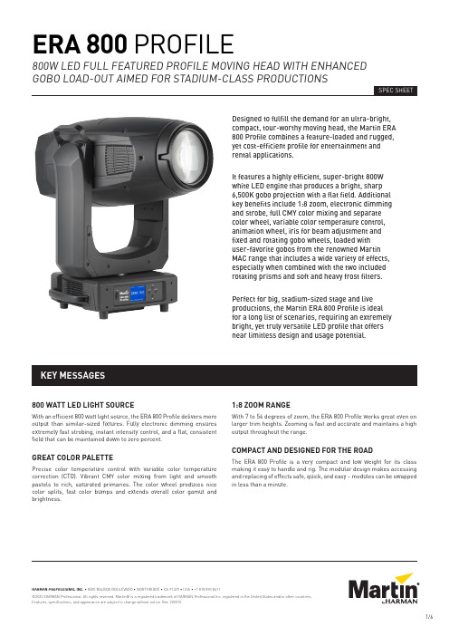
800 WATT LED LIGHT SOURCEWith an efficient 800 watt light source, the ERA 800 Profile delivers more output than similar-sized fixtures. Fully electronic dimming ensures extremely fast strobing, instant intensity control, and a flat, consistent field that can be maintained down to zero percent.GREAT COLOR PALETTEPrecise color temperature control with variable color temperature correction (CTO). Vibrant CMY color mixing from light and smooth pastels to rich, saturated primaries. The color wheel produces nice color splits, fast color bumps and extends overall color gamut and brightness.1:8 ZOOM RANGEWith 7 to 56 degrees of zoom, the ERA 800 Profile works great even on larger trim heights. Zooming is fast and accurate and maintains a high output throughout the range.COMPACT AND DESIGNED FOR THE ROADThe ERA 800 Profile is a very compact and low weight for its class making it easy to handle and rig. The modular design makes accessing and replacing of effects safe, quick, and easy – modules can be swapped in less than a minute.KEY MESSAGES Designed to fulfill the demand for an ultra-bright, compact, tour-worthy moving head, the Martin ERA 800 Profile combines a feature-loaded and rugged, yet cost-efficient profile for entertainment and rental applications.It features a highly efficient, super-bright 800W white LED engine that produces a bright, sharp 6,500K gobo projection with a flat field. Additional key benefits include 1:8 zoom, electronic dimming and strobe, full CMY color mixing and separate color wheel, variable color temperature control, animation wheel, iris for beam adjustment and fixed and rotating gobo wheels, loaded withuser-favorite gobos from the renowned Martin MAC range that includes a wide variety of effects, especially when combined with the two included rotating prisms and soft and heavy frost filters. Perfect for big, stadium-sized stage and live productions, the Martin ERA 800 Profile is idealfor a long list of scenarios, requiring an extremely bright, yet truly versatile LED profile that offers near limitless design and usage potential.MODELS• ERA 800 Profile in cardboard box .............................P/N 9025123581• ERA 800 Profile White in cardboard box ..................P/N 9025123582• Flightcase, two unit, for 2 x ERA 800Performance / Profile ...................................................P/N 91512255 INCLUDED ITEMS• Two omega brackets with 1/4 turn fastenersfor rigging clamp attachment .................................2 x P/N 91602001 RELATED ITEMS• Martin Companion software suite(incl. firmware uploader) .......Free download from • Martin Companion Cable USB/DMXhardware interface .......................................................P/N 91616091• Martin RDM 5.5 Splitter ................................................P/N 90758150CONVERSION KITS• Framing Module(converts ERA 800 Profile to Performance) ..............P/N 5125961-00• Gobo Wheel 3 Effects Module(converts ERA 800 Performance to Profile) ..............P/N 5131799-00OPTICAL ACCESSORIES• CRI Boost Filter(CRI >80, installs on gobo wheel) ..............................MAR-91614059POWER INPUT CABLES• Power Input Cable, H07RN-F, 2.5 mm 2, 14 AWG, bare ends to TRUE1 NAC3FX-W(female), 1.5 m (4.9 ft.) ..................................................P/N 91611797• Power Input Cable, H07RN-F, 2.5 mm 2, 14 AWG, bare ends to TRUE1 NAC3FX-W(female), 5 m (16.4 ft.) ...................................................P/N 91611786• Power Input Cable, SJOOW, 12 AWG, bare ends to TRUE1 NAC3FX-W(female), 1.5 m (4.9 ft.) ..................................................P/N 91610173• Power Input Cable, SJOOW, 12 AWG, bare ends to TRUE1 NAC3FX-W(female), 5 m (16.4 ft.) ...................................................P/N 91610174POWER RELAY CABLES, 16 A, FOR RELAYING POWER TO A SECOND FIXTURE AT 200 - 230 V MAINS POWER• Power Relay Cable, H07RN-F, 2.5 mm 2,TRUE1 to TRUE1, 0.45 m (1.5 ft.) ..................................P/N 91611784• Power Relay Cable, H07RN-F, 2.5 mm 2,TRUE1 to TRUE1, 1.2 m (3.9 ft.) ....................................P/N 91611785• Power Relay Cable, H07RN-F, 2.5 mm 2,TRUE1 to TRUE1, 2.5 m (8.2 ft.) ....................................P/N 91611796• Power Relay Cable, SJOOW, 12 AWG,TRUE1 to TRUE1, 0.45 m (1.5 ft.) ..................................P/N 91610170• Power Relay Cable, H07RN-F, 2.5 mm 2,TRUE1 to TRUE1, 1.2 m (3.9 ft.) ....................................P/N 91610171• Power Relay Cable, H07RN-F, 2.5 mm 2,TRUE1 to TRUE1, 2.5 m (8.2 ft.) ....................................P/N 91610172POWER CONNECTORS• Cable Connector, Neutrik powerCON TRUE1NAC3FX-W TOP (female) .........................................P/N 91611789HU • Cable Connector, Neutrik powerCON TRUE1NAC3FX-W TOP (male) ............................................P/N 91611788HUINSTALLATION HARDWARE• Hand-coupler Clamp ....................................................P/N 91602005• Safety Cable, SWL 60 kg,BGV C1 / DGUV 17, black ..............................................P/N 91604006• Safety Cable, SWL 60 kg,BGV C1 / DGUV 17, silver ..............................................P/N 91604007DYNAMIC EFFECTSElectronic 'shutter' effect......................S trobe effect, pulse effects, instantopen and blackoutElectronic dimming ...............................0 - 100%, four dimming curve options Color mixing ..........................................CMY, independently variable 0-100% Color temperature control ....................Variable 6500 - 2700 KColor wheel............................................6 color filters plus openRotating gobo whee l ..............................6 gobos plus open, wheel rotation, goborotation, indexing and shakeSecond rotating gobo whee l ..................6 gobos plus open, wheel rotation, goborotation, indexing and shakeStatic gobo wheel ..................................7 gobos plus open, wheel indexing,rotation and shakeGobo animation......................................A nimation wheel, indexing, continuousrotation with variable speed anddirection Iris..........................................................0-100%Zoom ......................................................Motorized Focus......................................................Motorized Prism......................................................2 rotating/indexing prisms(4-facet circular and 6-facet linear) Frost.......................................................Soft frost effect and heavy frost effect Pan .........................................................540°, coarse & fine control and speed Tilt ..........................................................260°, coarse & fine control and speedCONTROL AND PROGRAMMINGControl options ......................................DMX16-bit control .........................................Dimming, CMY, CTO, pan and tilt Setting and addressing .........................Control panel with backlit LCD display DMX channels, ERA 800 Performance..42DMX channels, ERA 800 Profile (36)DMX compliance ITT DMX512/1990RDM compliance....................................ANSI/ESTA E1.20Transceiver ............................................Opto-isolated RS-485OPTICSFront lens diameter...............................160 mm (6.3 in.)Zoom range............................................7° - 56° (1:8)Light source...........................................800 W LED engineMinimum LED lifetime...........................20 000 hours (to >70% luminousoutput)**Figure obtained under manufacturer's test conditionsSpecifications 35PHOTOMETRIC DATALight engine luminous output...............70000lumensFixture luminous output........................34000 lumensCCT (Calibrated Color Temperature) ....6500 K (+/-250K)CRI (Color Rendering Index) .................>70CQS (Color Quality Scale) ......................>67TM-30 Rf(IES TM-30-15 Fidelity Index)................>65TM-30 Rg(IES TM-30-15 Gamut Index).................>93TLCI (Television LightingConsistency Index) ................................>44LED refresh rate ...................................3600 Hz CONSTRUCTIONHousing..................................................H igh-impact flame-retardantthermoplasticColor.......................................................BlackProtection rating....................................IP20GOBOSExternal diameter .................................30.0 mm +0 / -0.2 mm (1.181 in.+0 / -0.008 in.)Maximum image diameter ....................25 mm (0.98 in.)Maximum gobo thickness .....................1.1 mm (0.04 in.)Material..................................................Borofloat 33Coating...................................................Heavy matted aluminum INSTALLATIONMounting points.....................................2 pairs of 1/4-turn points for 106 mm(4.17 in.) center-to-center omegabracketsLocation .................................................D ry location only, must be fastened tosurface or structureOrientation.............................................AnyMinimum distance tocombustible materials .........................0.2 m (8 in.)Minimum distance toilluminated surfaces .............................2.0 m (6.6 ft.)CONNECTIONSAC mains power input ...........................N eutrik TRUE1 socket, accepts TRUE1NAC3FX-W (TOP) connectorAC mains power throughput .................N eutrik TRUE1 socket, accepts TRUE1NAC3MX-W (TOP) connectorDMX and RDM data in/out .....................5-pin locking XLRELECTRICALAC power................................................100-240 VAC (nominal), 50/60 Hz Power supply unit..................................Auto-ranging electronic switch mode Maximum total power consumption .....1397 WPower consumption, all effects static,zero light output ....................................64 WHalf-cycle RMS inrush current at230 V, 50 Hz............................................10.3 ARecommended MCB (MiniatureCircuit Breaker) per IEC60898/UL489/CSA C22.2 No. 5..............Type DTYPICAL POWER AND CURRENT120V, 60Hz .............................................10.8 A, 1270 W, PF 0.99230V, 50Hz .............................................5.5 A, 1240 W, PF 0.97Figures are typical, not maximum. Measurements made at nominal voltage with all LEDs at full intensity. Allow for a deviation of +/- 10%. PF = power factorTHERMALCooling...................................................F orced air (temperature regulated,low noise)Maximum surface temperature,steady state, at Ta 40° C .......................70° C (158° F)Maximum ambient temperature(Ta max.) ................................................40° C (104° F)Minimum ambient temperature(Ta min.) .................................................5° C (41° F)Maximum total heat dissipation(calculated, +/- 10%) .............................4770 BTU/hr.APPROVALSGlobal CB Certification/IECEE ..............IEC 60598-2-17 (IEC 60598-1)EU safety................................................E N 60598-2-17 (EN 60598-1), EN 62471,EN62493EU EMC ..................................................E N 55015; EN 55032; EN 55035;EN 61000-3-2, EN 61000-3-3, EN 61547 US safety................................................UL 1573US EMC ..................................................FCC Part 15 Class BCanadian safety .....................................CSA C22.2 No. 166Canadian EMC........................................I CES-3 (B) / NMB-3 (B); ICES-5 (B) /NMB-5 (B)Australia/NZ ..........................................RCM36 ERA 800 Performance / Profile Safety and Installation ManualPHYSICALLength (head) .........................................608 mm (24.0 in.)Width (base) ...........................................290 mm (11.4 in.)Length (base) .........................................416 mm (16.4 in.)Width (across yoke) ...............................431 mm (17.0 in.)Height (head straight up) ......................802 mm (31.6 in.)Height (maximum) .................................821 mm (33.5 in.)Minimum center-to-center distancein side-by-side installation ...................730 mm (28.8 in.)Weight ....................................................40.0 kg (88.2 lbs.)。
CleanMax ZM-800 无线室内清洁器说明书

Owner’s Manualfor the CordlessCordless Model ZM-800Congratulations!You have purchased a vacuum cleaner that will provide efficient, dependable service. Your CleanMax vacuum cleaner is made using high quality materials and superior workmanship. Please read these operating instructions carefully before you use your vacuum.IMPORTANT:To activate your warranty, within 30 days of purchase, please register your warranty online at .Please fill out warranty information located on the Owner’s Information Section and keep it for your records.Key Replacement PartsGenuine Zoom HEPA Media Vacuum Bags: CLH-6Genuine Zoom Paper Vacuum Bags: B211-8800Genuine Zoom Vacuum Belts: CMZM-B2CONTENTS Getting StartedI mportant Safety Instructions 2 Polarization Instructions 3 Description of the Vacuum 4 Assembling the Vacuum 5OperationB attery Charging 6 Battery Life Display 6 Reclining the Handle 6 On/Off Switch 7 Edge Cleaning 7 Automatic Carpet Height Adjustment 7 Bare Floor Cleaning 8 Vacuuming Under Furniture 8Maintenance and CareR eplacing the Vacuum Bag 9 Removing and Reinstalling the Battery 10 Removing and Reinstalling the Bottom Plate 11 Replacing the Vacuum Belt 12 Replacing the Squeegee 13For Best Performance14 Warranty15IMPORTANT SAFETY INSTRUCTIONSWhen using an electrical appliance, basic precautions should always be followed, including the following:READ ALL INSTRUCTIONS BEFORE USING THIS APPLIANCE. FOR COMMERCIAL USE ONL Y. The manufacturer cannot accept responsibility for damagecaused when the appliance is not used according to theinstructions, or for uses other than those for which itwas intended.WARNING: To reduce the risk of fire, electric shock, damage or injury:IMPORTANT:• F ully assemble vacuum before operating.• Use and store in a dry location.• D o not use outdoors or on wet surfaces.• D o not allow to be used as a toy. Close attentionis necessary when used by or near children.• U se only as described in this manual.• D o not use charger with damaged cord or plug. If appliance or charger is not working as it should, has been dropped, damaged, leftoutdoors, or dropped into water, return it to your Authorized CleanMax Retailer for service. • D o not pull or carry charger by cord, use cord as a handle, close a door on the cord, or pull cord around sharp edges or corners. Do not run appliance over cord. Keep cord away from heated surfaces.• D o not unplug charger by pulling on cord. To unplug charger, grasp the plug, not the cord.• D o not handle charger, including charger plug, and charger terminals with wet hands.• D o not put any object into openings. Do not use with any opening blocked; keep free of dust, lint, hair and anything that may reduce air flow. • K eep hair, loose clothing, fingers and all parts of the body away from openings and moving parts.• D o not pick up anything that is burning or smoking, such as cigarettes, matches or hot ashes.•D o not use without vacuum bag in place.• Use extra care when cleaning on stairs.• D o not use to pick up flammable or combustible liquids such as gasoline or use in areas where they may be present.• D o not attempt to service the unit while charger is plugged in.• Do not charge the unit outdoors.• O nly charge in temperatures between 0-45ºC (32-113ºF).• D o not open, crush, expose to heat above100ºC (212ºF) or incinerate the battery even if it is severely damaged. The battery can explode in a fire.• U se only with the Cordless Battery Vacuum Charger supplied - P/N 10201026 Winkind. (C223-2000)• T he battery and charger have no user serviceable parts.• B atteries must be disposed of responsibly. • R emove the battery before removing the bottom plate.POLARIZATION INSTRUCTIONSPower Cord, 2-Wire Polarized CordT his product is equipped with a polarized alternating current line plug (a plug having one blade wider than the other). This plug fits into the power outlet only one way. This is asafety feature. If you are unable to insert the plug fully into the outlet, try reversing theplug. If the plug should still fail to fit, contact an electrician to replace the obsolete outlet.Do not defeat the safety purpose of the polarized plug.State of California Proposition 65 Warnings:WARNING: T his product contains one or more chemicals known to the State of California to cause cancer.WARNING: T his product contains one or more chemicals known to the State of California to cause birth defects or other reproductive harm.DESCRIPTION OF THE VACUUM1 Ergonomic Handle2 On/Off Power Switch3 Bag Compartment4 Vacuum Nozzle5 Headlight6 Furniture Guard7 Handle Release Pedal8 Battery Pack9 Charge Point 10 Battery Life Display 11 Battery Release Button 12 Carry HandleASSEMBLING THE VACUUMAttaching the Handle to the VacuumNOTE: Do not turn on the vacuum until it iscompletely assembled.The vacuum cleaner and the handle arepacked separately and require assembly.• R emove the handle bracket by removing thetwo screws (Fig. 1).• P lace handle onto the back of the vacuum, aligning holes with pegs (Fig. 2).• P lace the handle bracket back into position (Fig. 3).• S ecure with two screws removed in Fig. 1. Tuck the cord into the space to the left of the handle.• O pen the bag compartment to ensure a vacuum bag is in place.• Your vacuum is now ready for use.Pre-Charged BatteryThe battery is partially charged and will run for a short time. To fully charge the battery see Battery Charging (page 6).Fig. 1Fig. 2 Fig. 3OPERATION• T he battery is located on the back ofthe vacuum. It can be charged while installed onthe vacuum and charged independently (seeRemoving and Reinstalling the Battery (page 10).• P lug the AC cable into the charger and into awall socket (Fig. 1).• Pon the battery. (Fig. 2).• T he Charger LED light will be red duringcharging and will turn green when the batterypack is fully charged.Battery Life Display• P ress the white button on the battery to illuminatethe LED lights.• W hen the battery is fully charged there will be(Fig. 3).• A s the battery is discharged during use, thenumber of green lights showing will reduce fromfour (4) to none (0).• W hen all of the green lights are off and only thered light is showing, there is a small amount oftime remaining before the battery will be fullydischarged and will require recharging. Reclining the Handle• P ress the Handle Release Pedal located on theback of the vacuum with your foot to recline thehandle (Fig. 4).Fig. 3 Fig. 2Removing and Reinstalling the BatteryNOTE: Turn the vacuum off. If the battery charger is plugged into the charge point on the vacuum, remove the charger from the charge point before removing the battery.The battery can be removed and charged independently from the vacuum.• T o remove the battery push up on the release button and lift the battery off (Fig. 1).• T o replace the battery, line up the bottom of the battery with the posts at the base of the battery mount. Push the battery in until it clicks (Fig. 2).Fig. 2MAINTENANCE AND CAREMAINTENANCE AND CAREFig. 1Fig. 2Removing and Reinstalling the Bottom PlateWARNING! T o Reduce the Risk of ElectricalShock or Injury from Moving Parts, Turn the Vacuum Off and Remove the Battery Before Servicing or Cleaning the Vacuum.T o Remove the Bottom Plate:• Make sure the vacuum is turned Off.• R emove the battery (see Removing andReinstalling the Battery, page 10). • P ress the handle release pedal to place thevacuum cleaner in the flat position.• T urn the vacuum cleaner over, exposing thebottom plate. • T urn the two screws a quarter turn to releasethe bottom plate (Fig. 1). Remove the bottom plate.T o Reinstall the Bottom Plate:• A lign the front edge of the bottom plate into thenotches inside the nozzle (Fig. 2). • P ress the bottom plate into position until theplate “clicks” on both sides. Tighten the two screws a quarter turn to secure the bottom plate.• R eplace the Battery (see Removing andReinstalling the Battery, page 10).Fig. 2Replacing the Vacuum BeltWARNING! T Cleaning the Vacuum.NOTE: occurring. Replace if needed.• T the Charge Point.• R the Battery, page 10). • R • R shaft.• L and the brushroll (Fig. 1). • R einstall the brushroll into the nozzle. Turnthe brushroll by hand, making sure the belt isnot twisted and all rotating parts move smoothly (Fig. 2).• R einstall the bottom plate (see Removing andReinstalling the Bottom Plate, page 11). • R eplace the battery (see Removing and Reinstallingthe Battery, page 10). MAINTENANCE AND CAREOwner’s information(keep this for your records)The model and serial number of this product may be found on the bottom of the unit. You should note the model and serial number of your unit in the spaces provided below, and retain this book as a permanent record of your purchase.Date of purchase ____________________________________________________Serial number _______________________________________________________Model number ______________________________________________________ Purchased from:Store Name _______________________________________________________ Address _______________________________________________________City, State, Zip ______________________________________________________ Telephone _______________________________________________________For Best Performance• K eep your vacuum clean and in good operating condition.• C hange vacuum bag when the bag is 2/3 full to maximize cleaning performance.• A lways use genuine vacuum bags and replacement parts. Use of other products may result in poor cleaning performance, potential vacuum cleaner damage and may void vacuum warranty. Genuine products are designed for maximum cleaning performance.• Store your machine carefully in a dry area.• For optimum cleaning performance and safety, follow your owner’s manual instructions.WarrantyWhat is Covered:This warranty covers any defects in material and workmanship in your new CleanMax vacuum.How Long Coverage Lasts:Warranty coverage for your CleanMax vacuum lasts one year.What is Not Covered:• D amage to the vacuum which occurs from neglect, abuse, alterations, accident, misuse or improper maintenance.• N ormal replacement items: belts, squeegees, agitator brush strips and disposable bags.What CleanMax Will Do:This warranty provides, at no cost to you, all labor and parts to place this vacuum in correct operating condition during the warranted period.How to Get Service:Warranty service can only be obtained by presenting the vacuum to the retailer where original purchase was made. A proof-of-purchase and product serial number will be required before service is rendered.THIS WARRANTY IS EXCLUSIVE AND IN LIEU OF ANY AND ALL OTHER WARRANTIES WHETHER WRITTEN, ORAL, EXPRESSED OR IMPLIED, (INCLUDING ANY WARRANTY OF MERCHANTABILITY OR FITNESS FOR A PARTICULAR PURPOSE). THIS WARRANTY DISCLAIMS LIABILITY FOR INCIDENTAL, OR CONSEQUENTIAL DAMAGES.How State Law Applies:This warranty gives you specific legal rights, and you may also have other rights which vary from state to state.CleanMax Vacuum CleanersPO Box 730Fenton, MO 63026。
- 1、下载文档前请自行甄别文档内容的完整性,平台不提供额外的编辑、内容补充、找答案等附加服务。
- 2、"仅部分预览"的文档,不可在线预览部分如存在完整性等问题,可反馈申请退款(可完整预览的文档不适用该条件!)。
- 3、如文档侵犯您的权益,请联系客服反馈,我们会尽快为您处理(人工客服工作时间:9:00-18:30)。
MIC系列有毒有害智能气体检测仪产品说明书
深圳市逸云天电子有限公司
深圳市逸云天电子有限公司产品说明书1.概述
MIC-800系列便携式智能气体检测仪,采用了最先进的大规模集成电路技术、国际标准智能化技术水准设计技术及专有数字模拟混合通讯技术而设计的完全智能化的气体检测仪。
MIC-800系列气体检测仪技术先进、性能卓越、稳定性高、可检测的气体种类繁多,具有恢复出厂默认设置和自诊断功能,使用和维护方便,极大的满足了工业现场安全监测对设备高可靠性的要求,广泛应用于石油、化工、环保、冶金、炼化、燃气输配、生化医药、农业等行业。
2.技术特点
●高精度、高分辨率
●宽量程,最大量程可达0~50000ppm或0~100%Vol
●即插即用国际标准智能化传感器,现场维护非常方便
●独特的LCD带背光设计技术,现场设备的观察、维护不再受光线变化的
困扰
●全量程范围的数字温度补偿
●通过3个按键可实现查看、设定、校准等功能
●本安电路设计,外壳防雨、防腐蚀,耐磨损
●大容量的可充电锂电池及充电保护电路
●一键恢复功能,让您操作时无后顾之忧
1
产品说明书深圳市逸云天电子有限公司3.技术参数
壳体材料:ABS
外型尺寸:125×52×30mm(L×W×H)
防爆等级:Exia II CT6
防护等级:IP65
整机重量:200g
精度:±3%F.S.
检测方式:扩散式或泵吸式
浓度单位:ppm、%VOL、%LEL、mg/m3
报警方式:声光、振动
工作温度:-40~70℃
工作湿度:0 ~ 95% RH 非凝露
工作电压:3.6VDC
报警电流:150mA
工作电流:扩散式10mA,泵吸式60mA
电池容量:1800mA,带充电保护电路
充电器规格:4.2VDC, 1A
2
深圳市逸云天电子有限公司产品说明书4.外型图片
外形尺寸:125×52×30mm (L×W×H)
3
产品说明书 深圳市逸云天电子有限公司
4
5. 操作说明
5.1 按键定义:本机共设三个按键,⊙键、↑ 键、↓ 键 (从左到右顺序) ⊙键为电源开关并起确认功能,↑ 键为移位键,↓ 键起翻页
及数字加减的作用。
5.2 开机方法:
长按 ⊙键5秒钟不放,到了5秒钟后自动开机,开机
以后显示的画面依次为:气体名称、最大量程及
单位和电量,2秒钟后开始显示预热倒计时120秒,
如果不想等待,按一下 ⊙键直接进入正常测量界面,
左下角显示气体种类,此时振动马达及蜂鸣器、指示灯
都报警1 次表示正常启动,如果电量不足或者检测
不到传感器,则一直报警下去,此时如果按一下⊙键
起消音作用,声音及振动马达、指示灯都停止工作,但
是屏幕上“Alarm ”字样仍在闪烁,如果是电量不足,
电量图标闪烁,如果是检测不到传感器,显示
“ FAULT ” 字样, 此时再按一下⊙键,声音及振动
马达、指示灯继续工作。
如果仪器是泵吸式,屏幕上就
会显示泵的图标,并且一直在旋转,如果没有泵就不显示
这个图标。
右图为正常启动后显示的画面(以CO 为例)
深圳市逸云天电子有限公司 产品说明书
5 6、菜单设置
密码设置:依次按⊙键、↑键、↓键 ,在2秒钟内完成才有效
菜单定义:Z 、S 、FS 、AL 、AH 、CER 、DEFA 、OUT
6.1、零点校准 Z
如果传感器出现零点漂移过大,需要
进行零点校正,如图1 所示 图1
零点设置菜单默认为“N ”,如图2所示,需要
进行是否操作的确认。
图2
如果确认要校准零点,在零点设置菜单通过
↓ 键修改为“Y ”,如图3所示 图3
按 ⊙键确认进行零点校准,如果校准成功,
左下角出现 “YES ” 字样,如图4所示 图4
如果校准不成功,左下角出现 “NO ” 字样,
如图5所示 图5
产品说明书 深圳市逸云天电子有限公司
6
6.2、目标点校准 S
如果传感器使用时间过长,需要进行灵敏度
校正,通过↓ 键选到 “S ”选项,按一
下⊙键进行修改,如图6 所示 图6
目标点浓度设置菜单默认为“N ”,如图7
所示,需要进行是否操作的确认。
图7
如果确认要校准目标点,在目标点设置菜单通过
↓ 键修改为“Y ”,如图8所示 图8
按 ⊙键确认进行目标点校准,如果校准成功,
左下角出现 “YES ” 字样,并且数值变为在菜单
“CER ”里设置好的值,如图9所示 图9
如果校准不成功,左下角出现 “NO ” 字样,
如图10所示 图
10
深圳市逸云天电子有限公司 产品说明书
7 6.3、满量程设置 FS
如图11所示,通过↓ 键选到 “FS ”
选项,按一下⊙键进行修改,↑键进行
移位,修改后再按⊙键保存。
图11
6.4、一级报警点设置 AL
如图12所示,通过↓ 键选到 “AL ”
选项,按一下⊙键进行修改,↑键进行
移位,修改后再按⊙键保存。
图12
6.5、二级报警点设置 AH
如图13所示,通过↓ 键选到 “AH ”
选项,按一下⊙键进行修改,↑键进行
移位,修改后再按⊙键保存。
图13
产品说明书 深圳市逸云天电子有限公司
8
6.6、目标点浓度设置 CER
如图14所示,通过↓ 键选到 “CER ”
选项,按一下⊙键进行修改,↑键进行
移位,修改后再按⊙键保存。
图14
6.7、恢复出厂默认设置 DEFA
如图15所示,通过↓ 键选到 “DEFA ”
选项,按一下⊙键进行修改,需要进行 图15
是否操作的确认。
6.8 退出菜单设置 OUT
如图17所示,通过↓ 键选到 “OUT ”
选项,按一下⊙键进行设置并退出
图17
深圳市逸云天电子有限公司产品说明书7.设备维护
检测仪在正常的使用中,传感器的有效使用寿命为24-36个月。
在有效使用寿命期内,每6个月或1年要定期对传感器进行一次标定检查,以保证气体监测准确有效。
超过有效使用期的和有故障的传感器必须进行更换。
7.1 传感器更换
在传感器出现故障后,请将仪器寄回厂家更换。
7.2传感器标定
详见6.2 描述。
在标准气体未准备好时请勿操作,万一发生误操作,可以参照6.7描述,恢复出厂默认设置。
校准之前参照6.2 描述,预先把要校准的浓度值设置好,再通标准气体,标准气体的流量控制在300毫升/分钟
8.注意事项
●严禁在现场充电或拆卸仪器
●严禁带电更换传感器
●检测仪的标定检查要定期进行
●超过有效使用期和有故障的传感器要及时更换
●避免用高于测量量程的气体冲击传感器,此举可能会损坏传感器,
人为损坏的情况不在保修范围之内。
9
9.技术性能及参数主要技术指标
11
13
注:其它未在上表列出的气体可来电咨询。
15。