HDS USP 更换硬盘手册
HDS-高端USP-VM磁盘存储产品介绍

1.1 HDS 高端USP VM磁盘存储产品介绍1.1.1 HDS USP VM磁盘存储产品硬件介绍Hitachi TagmaStore™网络存储控制器USP VM是HDS2007年最新推出的机架式设备,符合企业的成本要求。
它采用了Hitachi Universal Star Network™交换架构,提供由业内领先的Hitachi TagmaStore通用存储平台带来的,经过验证的企业级功能:外部存储虚拟化、逻辑资源分区和通用复制。
HDS TagmaStore USP VM为HDS公司的第四代全光纤交换式企业级磁盘存储系统,内部仍然延续了HDS的CrossBar的交换式结构(通过Cache Switch,实现前端主机接口控制器、后端磁盘通道接口控制器数据到Cache的数据快速交换),采用了Hitachi自主研发Hi-Star III交换芯片,具有更高的数据交换能力,因此可以提供更高的内部带宽。
正是因为这样的传承,USP VM为用户带来了前所未有的性能、可用性和可靠性,以及先进的存储管理和数据复制功能。
用户可以把各种异构存储系统整合为一个虚拟池,通过一个中央控制台,使用一套通用的工具进行管理,从而简化存储环境,最大限度地利用现有资源,降低总体拥有成本。
一个新的存储类型根据IDC的研究,通用存储平台代表了一种新型存储技术,能够“潜在影响”存储解决方案市场变化的产品。
USP VM是这种类型的入门级产品,可以提供:•基于控制器的虚拟化管理,最多可管理96PB内部和外接存储•8个逻辑分区、专用高速缓存、端口以及内部和外部容量,以保证应用服务质量(QoS)•在异构存储系统之间实现通用复制,保证业务连续性•HDS TagmaStore USP VM提供虚拟化技术HDS TagmaStore USP VM HDS提供存储虚拟化的技术,可以实现将不同厂商的存储系统集合到同一个存储池中。
HDS TagmaStore USP VM内部的磁盘为内部存储资源,与之相连的其它存储设备上的资源是外部资源(可外连的磁盘存储设备包括Lightning Storage 9900V, 9900, 7700E、Thunder Storage 9500V&9200、IBM Shark、EMC Symmetrix&DMX、EMC CX系列等)。
HDS_USPV日常维护手册
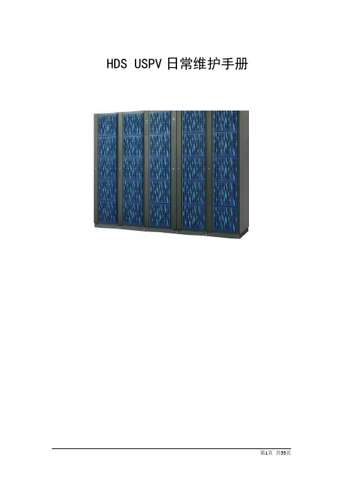
HDS USPV日常维护手册目录1.背景情况 ...................................................... 错误!未定义书签。
1.1. 实施需求 ...................................................................... 错误!未定义书签。
1.2. HDS USPV和Brocade交换机的详细配置 ................. 错误!未定义书签。
2.实施前准备工作........................................... 错误!未定义书签。
3.安装实施 ...................................................... 错误!未定义书签。
3.1. 物理安装 ...................................................................... 错误!未定义书签。
3.2. SAN设计示意图 .......................................................... 错误!未定义书签。
3.3. USPV电源 .................................................................... 错误!未定义书签。
3.4. Brocade 48000的Extended Fabric Keys ..................... 错误!未定义书签。
3.5. USPV的端口设置 ........................................................ 错误!未定义书签。
3.6. LDEV对主机的分配(Mapping) .............................. 错误!未定义书签。
笔记本换硬盘教程

笔记本换硬盘教程笔记本换硬盘教程(500字)在使用笔记本电脑的过程中,有时我们可能需要更换硬盘来获得更大的存储空间或更高的性能。
本文将为您提供一份简单易懂的笔记本电脑换硬盘教程,帮助您完成这项任务。
首先,您需要准备工具和材料。
您需要一把小螺丝刀、一个笔记本电脑硬盘(确保其与您的笔记本电脑兼容)、一个USB 闪存驱动器和一个 USB硬盘外壳。
接下来,备份您的数据。
在换硬盘之前,务必备份您的所有重要文件和数据。
您可以将它们存储在另一个硬盘或使用云存储服务。
关机并拔下电源。
在进行任何维修或升级工作之前,都要确保电源已经断开。
然后,关闭您的笔记本电脑并将电源适配器拔出。
找到硬盘安装位置。
笔记本电脑的硬盘通常位于底部,您可能需要查看您的用户手册以找到它的确切位置。
在找到之后,使用小螺丝刀将硬盘盖上的螺丝拧松,然后轻轻将盖子取下。
拆下旧硬盘。
一旦打开硬盘盖子,您将看到硬盘连接到主板上的电缆。
小心地将电缆与硬盘分离,确保不要过度用力并导致损坏。
安装新硬盘。
将新硬盘插入正确位置,然后连接电缆。
确保硬盘连接牢固,不会松动。
用闪存驱动器启动计算机。
将您的USB闪存驱动器插入电脑,并通过BIOS或启动菜单将电脑设置为从该驱动器启动。
这样可以帮助您将操作系统和其他文件从旧硬盘复制到新硬盘。
将旧硬盘放入USB外壳。
为了保留旧硬盘上的数据,您可以将其放入一个USB硬盘外壳中,以便将来进行访问。
安装操作系统。
一旦完成数据复制过程,您可以将新硬盘作为主要引导设备,并重新安装操作系统。
这可以通过将操作系统安装介质插入USB驱动器并按照屏幕上的提示进行操作来完成。
最后,将备份的数据复制回新硬盘。
将备份的文件和数据从外部存储设备(例如USB硬盘外壳)复制回新硬盘。
确保您将它们放在新硬盘的适当位置,并删除旧硬盘上的所有文件。
以上就是一份简单易懂的笔记本电脑换硬盘教程。
请务必注意备份数据、小心操作,并确保新硬盘兼容您的笔记本电脑。
如果您不确定自己的操作,请咨询专业人士的帮助。
HDS存储VSP用户维护手册-v1.0

HDS 存储VSP 用户维护手册(2024年5月)目录一、设备维护 (3)1.1VSP配置信息 (3)1.2VSP系统架构 (3)1.3维护常用命令 (6)1.4VSP应急方案-上下电操作 (29)1.5设备巡检 (31)二、微码升级 (35)2.1微码升级的意义 (35)2.2微码升级的策略 (36)2.3微码升级的步骤 (36)三、故障处理 (40)3.1故障处理预案 (41)四、案例 (42)4.1硬盘更换步骤 (42)4.2CHA更换步骤 (45)4.3DKA更换步骤 (50)4.4CM更换步骤 (53)一、设备维护1.1 VSP配置信息1.2 VSP系统架构1.2.1 VSP系统架构图其系统架构采用了交换式架构,如下所示。
图2-1:VSP硬件技术架构1.2.2 VSP主要部件图2-2 VSP硬件主要部件图VSP的主要部件包括:✓前端卡(CHA):负责连接外部主机或存储交换设备,如小型机;✓后端卡(DKA):负责连接内部磁盘存储设备,如硬盘;✓数据缓存卡〔CPC):CHA访问后端磁盘时的数据缓存区域;✓内存条〔CM):CM的内存条;✓PCI-Express交换卡〔ESW〕:DKC数据交换控制卡;✓处理器板卡〔MPB〕:负责前端及后端数据的处理;✓磁盘〔HDD):存储设备的磁盘;✓备份盘〔Spare Disk〕:用作备份盘的磁盘;✓电池〔Battery):系统掉电时保存数据的电池;✓电源〔PS):系统供电及交换用的电源;✓风扇〔FAN):系统冷却用的风扇;✓控制台〔SVP):系统配置和管理监控的控制台〔一台笔记本电脑〕;✓线缆〔Cable〕:连接存储内部和外部各部件间的电缆;✓光纤接头〔SFP):光纤转换接头;1.2.3 VSP存储的磁盘分布图VSP的磁盘分布按照如下进行标识:HDDxyz_dd其中:xy=Cabinet〔盘柜〕;z=HDU number〔磁盘笼编号〕dd=HDD number〔磁盘编号〕图2-3:VSP磁盘位置图1.3维护常用命令当盘机出现故障,如磁盘、控制卡、电源、内存、电池到出现异常时,会产生SIM信息,同时盘时机根据故障的严重程度,将Message或Alarm灯亮起。
如何更换HDS USPV 硬盘(超详细教程)

如何更换HDS USPV 硬盘1.准备工作:●使用1字型螺丝刀或者六角扳手打开前柜门(6mm六角扳手)前面板指示灯panel里面兴许可以找到。
以防万一,尽量自备。
●获得机器的序列号(打开柜门后机架左下角标签)●获得机器SVP的IP 通过客户管理员获得或者使用附件中xls算出。
2.登入SVP:●将笔记本配置为同一网段后,使用远程桌面登入SVP 可将笔记本设置为(126.0.0.11255.0.0.0)●用户名:administrator 密码:raid-login3.检查SIM信息:●点击Info按钮弹出如下对话框点击LOG●List SIM●查看initial类型的消息确认数据已经完全拷贝到hot-spare盘中(COPY NORMAL END)如拷贝完成,则可进行更换硬盘操作如未拷贝完成则需等待拷贝完成再进行硬盘更换。
4.使用Maintenance找到更换硬盘:●点击主界面的Viewmode 将SVP改为【Modify Mode】●点击Maintenance打开如下界面,有坏硬盘的硬盘柜上会有叹号标示。
●继续点击带有叹号符号的硬盘柜●打开如下界面,需要更换的硬盘会闪烁提示点击硬盘符号●检查Device Status为【failed】确认是需要更换的硬盘后,在如下界面点击【Replace】进行硬盘更换。
不要选错。
●点击后会弹出如下对话框选择【YES】●特别注意:弹出如下对话框后先不要点击[OK] 请动手做硬盘更换后再回来点击OK按钮。
硬盘更换物理操作小贴士可通过下图示意找到要更换的硬盘硬盘对应指示灯会变红提示,特别注意:有2排指示灯上面那一排对应上面的硬盘,下面那排对应下面的硬盘。
●使用如下方法取下硬盘换上新硬盘,最好能佩戴静电手环。
●更换完成回到笔记本前点击[ok]●弹出如下对话框选择[yes]●点选OK 完成更换5.将SIM信息中的报错消除:●退回主界面点击Info按钮弹出如下对话框点击LOG ●List SIM选中所有initial类型的信息点选completed 将其置为完成状态。
HDS USPV 更换内存过程
1.查看报错信息•进入管理界面(CL)后,点击右上角的模式,将View Mode 改成Modify Mode •点击CL上的Information•点击log•点击list•查看报错信息,如果没有处理的错误status应该是initial。
双击错误信息会进入详细报错信息界面。
•这时可以看到是在1CA的PCB板上的CM11A这个内存有问题。
2. 硬件准备工作•更换的备件(内存)。
•机柜的钥匙(六角扳手)。
•一字螺丝刀。
•静电手镯。
3. 更换内存•点击CL里面的Maintenance•点击Disk Controller•点击Logic Box Cluster1•进入Logic Box Cluster1后,按照错误信息中的提示选择CACHE1CA,点击•点击后出现如下的界面•点击CACHE1CA窗口左上角的Replace按钮,然后选择Yes•系统自动开始压缩错误信息•压缩完信息后,会提示收集信息,收集信息前会提示我们输入这次错误的描述。
这次我们在这里点Cancel•然后会提示插入软盘拷贝信息,这次我们在这里点击Cancel•此时,PCB(CACHE1CA)板上的内存开始关闭,为一会移除做准备。
•在PCB(CACHE1CA)板上的内存全部离线后,会询问是否点亮将要更换内存PCB板上的指示灯。
选择Yes点亮。
•现在出现提示:替换PCB(CACHE-1CA),在更换内存后,再点击OK•这个时侯我们就要去USPV前进行更换操作了。
•打开USPV机柜门•戴好静电手镯(在后面的整个操作过程中不要摘掉静电手镯)•卸下控制柜下面的挡板•这时可以看到需要更换内存的那个PCB板(1CA)的红灯已经点亮。
用一字螺丝刀拧下1CA板下面的固定螺丝。
双手拉开PCB板两端的提手垂直拔出PCB(1CA)板子。
•放平PCB板子,最好在下面垫上防静电袋,在板子上找到需要更换内存的槽位(PCB 的每个槽位边上都能看到相应的编号)。
这里需要更换的是CM11A槽位上的内存。
HDDSurgery 硬盘头部更换工具指南说明书
HDDSURGERY Tools for data recovery expertsGuide for using HddSurgery™ head change tools:▪HDDS Sea 7200.10/.9/.8/ES p2-3 (2 or 3 platters) ▪HDDS Sea 7200.10/.9/ES p4 (4 platters)▪HDDS Sea 7200.9 p1 (1 platter)HDDSURGERYTable of contents:1. Introduction ……………………………………………………………………….. page 32. HddSurgery ™ head change tools ………………………………………… page 43. Supported models ……………………………………………………………… page 54. Head replacement process (10 steps)Step 1 - Handling the tool ………………………………………… page 6 Step 2 - Mounting the tool on actuator arm ……………… page 7 Step 3 - Lifting the heads …………………………………………. page 8 Step 4 - Securing the tool …………………………………………. page 9 Step 5 - Moving the tool outside of platters area .…….. page 10 Step 6 - Unscrewing the heads ………………………….……… page 11 Step 7 - Mounting the heads in a new drive ……………… page 12 Step 8 - Removing the securing pin ………………………….. page 13 Step 9 - Removi ng the tool outside of platters …………. page 14 Step 10 - Dismounting the tool …………………………………page 15HDDSURGERY 1.IntroductionThis guide is intended as a short course in handling of our tools for professionals in data recovery. It is assumed that the user is experienced in data recovery and familiar with "traditional" ways of saving data. This manual should not be taken as a guide for training.Using these tools without adequate software support is not recommended. It is recommended to use some of the proven systems for cloning, such as Ace Lab, Salvation Data, Copy-r and other products.It is possible to recover data without HddSurgery TM tools. In many cases, the known processes of hard drive head replacement are effective and sufficient. The general idea behind HddSurgery TM tools was to make sure that the process of replacing damaged hard drive heads goes with no errors. The use of HddSurgery TM tools prevents the ferromagnetic read/write heads to come in any kind of contact with the platter i.e. disk surface or other read/write heads. Also, with some basic procedures and short training, it is possible to let junior data recovery technicians handle complex tasks. With the development of these tools, we are trying to eliminate the element of luck that usually accompanies the process of data recovery.Experienced data recovery technicians or engineers can have great success even without our tools, but they can have absolute security only by using HddSurgery TM tools.Non-contact head replacement implies that there is no contact between the heads, or between heads and platters in the process of dismounting the donor heads and mounting heads on the patient drive. Traditional techniques of replacing the heads imply contact between the heads and contact of heads with the platters in data area. These problems especially come to light on drives that have suffered some form of physical damage.A donor selection process is not covered by these guidelines. If you have questions about compatibility, you can send them to HddSurgery TM support team on **********************HddSurgery TM is not responsible for any eventual damage caused by usage of our tools.TMHDDSURGERY2. HddSurgery ™ head change toolsSeagate hard drives belong in the category of disks that "park heads" above the magnetic platters. That way of functioning implies that, in a situation when the drive is powered off, heads are located on the surface that has no sensitive magnetic material. This allows drive to spin-up the motor to the required speed.Purpose of HddSurgery TM head change tools is to enable safe heads passage over the "data" area above platters surface, and to provide non-contact transfer to the patient disk.▪ HDDS Sea 7200.10/.9/.8/ES p2-3 (2 or 3 platters)This tool is made for safe and easy head replacement on Seagate 7200.10, 7200.9, 7200.8, Seagate ES and Maxtor DiamondMax 21 drives with 2 or 3 platters.▪ HDDS Sea 7200.10/.9/ES p4 (4 platters)This head change tool is made to safely and easily replace heads on Seagate 7200.10 and 7200.9 drives with 4 platters.▪ HDDS Sea 7200.9 p1 (1 platter)This head replacement tool is made for safe and easy head replacement on Seagate7200.9 and Maxtor DiamondMax 20 hard drives with 1 platter. These hard drives have a similar casing as other 7200.9 hard drives with 2 or 3 platters, but the height on which the platter rests is different. This is why a new tool was needed to support these specific hard drives.As there is no conceptual difference between these three tools, we will explain only thefunctioning of HDDS Sea 7200.10/.9/.8/ES p2-3 tool. In the case of HDDS Sea 7200.10/.9/ES p4 and HDDS Sea 7200.9 p1, apply the same procedure.During the whole procedure of head replacement, heads and platters have no physical contact. Heads are lifted over NON-data area and safely guided over the platters. In process of installing back the donor heads, same procedure needs to be done. Heads are guided over the platters with no contact and safely deployed in non-data area.HDDSURGERY3. Supported modelsHDDSURGERY4. Head replacement processStep 1 – Handling the toolWhen not in use, the tool should always be kept in a wooden box delivered with the tool. This way of keeping the tool prevents any possible damage which could appear if it ’s not handled correctly. When taking the tool out of the box, always hold it for the shank. Never hold the tool in the part where the head lifting snouts are. Due to sensitivity of hard drive platters to dust and any kind of contamination, be sure to clean the tool before its use. Tool can be cleaned with a piece of cotton wool and alcohol. When cleaning the head lifting snouts, be extremely gentle.Picture 1. (handling the tool)HDDSURGERYStep 2 - Mounting the tool on actuator armsRemove screws holding flat cable contact and with a finger push contact from the bottom upwards to release it. The pressure from below may cause flat cable contacts to pop out and possibly damage platters, so hold firmly top of a flat cable contact with another hand while pushing related plastic. Before applying pressure remove screws from their holes.Carefully center the tool over the center hole of the hard disc head. Take care that the notch on the bottom of the tool coincides with the commas in the actuator arm base. Tighten the screw to perform tool installation.Picture 2. (mounting the tool)With your right hand make sure that the tool shank with snouts remains in the area outside of the platters.IMPORTANTBe sure to tighten the screw in order to ensure good contact and proper tool height.HDDSURGERYStep 3 - Lifting the headsBy horizontally moving tool shank we slide the tool over platters. Construction of tools enables heads to lift on tool snouts by relatively small force. If you feel that the necessary force is greater than the expected, check tool positions and possible damage to the HDA assembly. Push the tool as far as limiter is allowing.Picture 3. (lifting the heads)HDDSURGERY Step 4 - Securing the toolThe tool has a hole at its edge, which coincides with the hole in the head. The leftmost position is necessary to ensure the bound between tool and actuator arm. Securing is being done with the securing pin.Picture 4. (securing the tool)When using HDDS Sea 7200.9 p1 tool on hard disks with one head, this step is skipped because these drives don’t have a hole in the arm through which a pin could be placed. Since this tool is not secured with a pin, be carefull in the next few steps that the head doesn’t slide off the tool in the process.IMPORTANTIf the connection of the tool and actuator arms is not properly engaged, heads slipping ispossible during disassembling.HDDSURGERYStep 5 - Moving the tool outside of platters areaBy vertical scrolling move the tool (previously secured by pin) to the initial position.Picture 5. (moving secured tool with heads outside of platters area)When using HDDS Sea 7200.9 p1 tool on hard drives with one head, push the back side of the head arm to move the heads off the platters. This is important because the heads could slip off the tool as they are not secured with a pin.HDDSURGERY Step 6 - Dismounting the headsWith the help of a standard flat screwdriver unscrew the tool together with the heads.Hold the tool with one hand because of the possibly contact with the platters. Turn screw driver counter clockwise until heads are free.While performing this step on hard drives with one head make sure that the head stays on the tool and that it doesn’t slide off.Picture 6. (dismounting the heads)HDDSURGERY Step 7 - Mounting the heads in a new driveUse the same screwdriver to screw the heads on new hard drive. When screwing the heads tighten the screw too, just in case it got loosen up during the manipulation. This operation is necessary because of possible changes in height! Turn the screw driver clockwise.Again, on hard drives with one head be carefull that the head doesn’t slide off the tool during this procedure.Picture 7. (mounting the heads on a patient drive)By horizontal force return the head back towards the central section of the platters.HDDSURGERY Step 8 - Removing the pinCarefully remove the securing pin when heads are above the parking zone.Picture 8. (remove the securing pin)HDDSURGERYStep 9 - Removing the tool outside of plattersHorizontally push tool shank with a finger to return the tool outside of platters.IMPORTANTWith your other hand, hold back side of the head arm (magnetic coil) to preventheads from moving.Picture 9. (returning the tool outside of platters)HDDSURGERY Step 10 - Dismounting the toolTake out the screw and remove the tool. While loosening use the assisting tool to make counter force.Picture 10. (removing the tool, using the assisting tool)Put the lid back and close the disk. Put PCB back and clone the drive.。
HDS-存储-USP维护管理手册-V1.0

HDS USP设备维护管理手册——VER 1.0第1章HDS USP日常检查项目 (3)第2章操作面板 (4)第3章设备启停 (6)3.1正常下电步骤 (6)3.2正常上电步骤 (6)3.3切断电源的步骤 (6)3.4切断电源后的上电步骤 (7)第4章异常处理 (8)第5章维护管理 (9)5.1通过SVP查看SIM信息 (9)5.2通过S TORAGE N AVIGATOR查看SIM信息 (10)第6章HDS动态路径管理软件――HDLM基本操作 (13)6.1HDLM命令路径 (13)6.2DLNKMGR帮助命令 (13)6.3DLNKMGR VIEW命令 (13)6.4O FFLINE命令 (15)6.5O NLINE命令 (15)第7章HDS热线服务电话 (17)第1章HDS USP日常检查项目第2章操作面板操作面板简介第3章设备启停3.1正常下电步骤确认主机已停止对磁盘系统的访问。
⏹Shutdown数据库;⏹Umount文件系统;⏹Varyoff VG。
停止使用SVP。
将操作面板的PS左边开关⑨往上拨,同时将右边的开关⑩往下拨(Enable +OFF),磁盘系统将顺序自动下电。
约5分钟后,除了BS-ON⑦灯(黄色)亮以外,其它指示灯都熄灭,磁盘下电完成。
3.2正常上电步骤将操作面板的PS左边开关⑨和右边开关⑩往上拨(Enable+ON),此时PS-ON⑧指示灯亮(绿色),磁盘系统将顺序自动上电。
约5分钟后READY①灯(绿色)亮,磁盘阵列上电完成。
确认控制器组件前面的Main switch处于关闭(OFF)状态(按一下Main switch off开关)。
3.3切断电源的步骤除非需要对电源供电进行更改/改造,否则请使用上述正常上下电步骤。
实施本步骤之前,请预先知会HDS公司。
执行正常下电步骤。
阵列下电完成后,关USP相应的断路器(在机柜的后面,每个机柜有两个断路器)。
此时BS-ON⑦灯(黄色)熄灭。
日立HDSVM存储磁盘更换文档

日立HDSVM存储磁盘更换文档HDS VM存储磁盘更换文档HDS VM存储磁盘更换文档2020-7-7蝌蚪成长记目录HDS VM存储磁盘更换步骤 (2)一、环境介绍 (2)1. 存储基本信息 (2)二、更换存储磁盘 (2)1. 磁盘更换步骤 (2)2. 热备盘状态检查 (2)3. 故障盘位置确认 (5)4. 更换故障盘 (6)5. 检查数据拷贝状态 (11)6. 修改SIM表内告警信息状态 (13)HDS VM存储磁盘更换步骤一、环境介绍1.存储基本信息设备名称:USP VM设备类型:USP VM数据磁盘数量:600GB/15000 /172热备盘个数:8个二、更换存储磁盘1.磁盘更换步骤●检查故障盘数据是否拷贝到热备盘;●确认故障盘位置;●故障盘更换;●检查数据是否从热备盘拷贝回数据盘;●修改SIM表内告警信息状态。
2.热备盘状态检查检查的目的是确认数据是否已经全部拷贝到热备盘中。
具体步骤如下:登录管理主机:选择“I nformation”选择“Log”选择“SIM”查看“SIM”内的信息查看initial类型的消息确认数据已经完全拷贝到hot-spare盘中(COPY NORMAL END)下图所示为开始数据拷贝工作下图提示为已经完成数据拷贝,此时可进行硬盘更换操作如未拷贝完成则需等待拷贝完成再进行硬盘更换。
3.故障盘位置确认登录管理主机:点击主界面的Viewmode 将SVP改为【Modify Mode】选择“Maintenance”打开“Maintenance”界面,如有坏盘,则硬盘柜上会有叹号显示,磁盘会闪烁,此位置即为故障盘位置:4.更换故障盘点击出现叹号的硬盘柜,故障磁盘会在此硬盘柜中闪烁提示,点击硬盘符号,选择故障的磁盘,检查Device Status为【failed】确认是需要更换的硬盘后。
在如下界面点击【Replace】进行硬盘更换点击【Replace】后,弹出下图对话框,提示“是否要更换此物理磁盘”点击上图的“yes”后,弹出下图对话框,大概意思为要替换的零件可能挂载在DKU上,请确认要更换的磁盘位置,如果确认磁盘位置无错,点击下图的“OK”。
笔记本更换硬盘教程
笔记本更换硬盘教程笔记本更换硬盘教程在使用笔记本电脑的过程中,我们有时候需要更换硬盘,可能是因为硬盘存储空间不足,或者是硬盘出现故障。
以下是一个简单的笔记本更换硬盘的教程,希望能对大家有所帮助。
步骤一:备份重要数据在更换硬盘之前,务必先备份笔记本中重要的数据,以免更换过程中丢失。
可以使用外接移动硬盘、云存储等方式进行数据备份。
步骤二:准备工具和硬盘首先需要准备一些工具,例如螺丝刀和相应的螺丝刀头。
此外,还需要一块新的硬盘,确保其与原硬盘相匹配,并提前购买好。
步骤三:关闭电源并取下电池在更换硬盘之前,需要先关闭笔记本电脑的电源,并取下电池。
这样可以确保更换过程中的安全,避免电流对硬件造成损坏。
步骤四:取下原硬盘根据具体的笔记本型号,找到硬盘的位置并取下。
通常需要拆卸笔记本电脑的底盖,然后找到硬盘所在的位置。
步骤五:更换新硬盘将新的硬盘放入原硬盘的位置,确保连接端口对齐。
然后使用螺丝刀将硬盘固定在原硬盘位置上,并插入连接线。
步骤六:关闭笔记本电脑将新硬盘连接好后,再次安装笔记本电脑的底盖,并将电池重新装入。
然后打开电源开关,开机。
步骤七:重新安装操作系统由于更换了硬盘,原来的操作系统和数据都会丢失,所以需要重新安装操作系统。
根据不同的操作系统版本,具体操作步骤可能略有不同,可以通过查阅相关资料和操作手册进行操作。
步骤八:恢复数据在成功安装操作系统后,可以使用之前备份的数据来恢复个人文件和设置。
可以通过外接移动硬盘、云存储等方式将备份的数据导入到新的硬盘中。
以上就是一个简单的笔记本更换硬盘的教程。
在进行更换硬盘的过程中,一定要谨慎操作,避免损坏其他部分。
如果不确定自己的操作能力,建议咨询专业人士或者将笔记本送修。
希望这篇教程能够帮助到大家。
笔记本换新硬盘教程
笔记本换新硬盘教程现代化的生活中,电脑已经成为我们必不可少的工具之一。
而笔记本电脑作为一种轻便的电脑设备,受到了许多人的喜爱和使用。
然而,随着时间的推移,笔记本电脑的硬盘容量可能不足以满足我们日益增长的数据存储需求。
那么,当我们需要更大容量的硬盘时,我们应该如何更换笔记本电脑的硬盘呢?下面是一个简要的教程介绍。
首先,我们需要准备的工具和材料有新的笔记本硬盘、螺丝刀、硬盘托架和数据线等等。
第一步,我们需要先关闭电脑并断开电源,以确保安全操作。
接下来,我们需要找到笔记本电脑的硬盘托架。
一般情况下,这个托架位于笔记本电脑底部的一块小拆卸盖上。
使用螺丝刀拧下盖子上的螺丝,并轻轻托起托架。
第二步,我们需要从原硬盘上拆下数据线和电源线。
这些线通常是用来连接硬盘和主板的,可以使用手轻轻拔下来。
在拆卸的过程中,要注意不要过度用力以免损坏线路。
第三步,将硬盘托架上的原硬盘取下。
有些托架是需要用螺丝固定在硬盘上的,我们可以使用螺丝刀拧下螺丝,然后将原硬盘从托架上取下。
如果托架是用卡口式连接的,只需直接将原硬盘抽离出来就可以了。
第四步,我们需要安装新的硬盘。
首先,将新硬盘固定在硬盘托架上。
如果是使用螺丝固定的托架,可将新硬盘对准托架上的孔,然后用螺丝刀拧紧螺丝。
如果是卡口式连接的托架,只需将硬盘轻轻插入托架即可。
接下来,将连接线插到新硬盘上的适当位置,确保连接牢固。
第五步,我们需要固定硬盘托架并连接上数据线和电源线。
将托架重新放回笔记本电脑的硬盘位上,然后用螺丝刀将其固定。
接下来,将数据线和电源线插入主板上对应的插槽,确保连接稳固。
最后,我们只需将电脑充电并开机,检查新硬盘是否正常工作即可。
总的来说,更换笔记本电脑的硬盘并不是一项很复杂的任务。
只要按照上述步骤进行操作,我们就可以顺利地更换笔记本电脑的硬盘,让我们的电脑拥有更大的存储空间,更好地满足我们的需求。
当然,在进行操作的过程中,我们要时刻注意安全,避免对电脑和硬盘造成不必要的损害。
HDS_VSP_G200安装配置指南

目录第一章产品概述 (2)1.1产品简介 (2)1.2型号升级 (2)1.3主要指标 (2)1.4高密度扩展柜 (3)1.5RAID支持 (3)1.6磁盘相关属性 (4)第二章存储外观说明 (4)2.1外观说明 (4)2.2设备安装 (5)2.3控制器及SVP的IP地址说明 (6)第三章安装和配置SVP (8)3.1登陆SVP (8)3.2 SVP前置面板说明 (10)3.3重装管理工具Storage Device (11)3.4微码更新 (12)第四章SNM2基本操作 (13)4.1登录管理工具 (13)4.2安装硬盘 (14)4.3Li ce n se管理 (18)4.4在线微码升级 (19)4.5创建热备盘 (21)4.6删除热备盘 (23)4.7端口设置 (24)4.8 RAID组划分 (25)4.9创建LDEVS (27)4.10 Pool配置 (30)4.11在pool上创建LDEVs (32)4.12 Host Group配置 (34)4.13添加外部卷 (40)4.14删除Pool (44)4.15格式化LEDVS (47)4.16 ADD lUN PATHS 就是映射卷到主机 (49)4.17删除LEDVs (50)4.18删除PG(Raid)组 (51)4.19删除外部卷 (52)4.20修改网络端口参数 (54)4.21其他操作 (55)4.22修改时间 (61)4.23 Warning告警灯消除 (62)第五章MPC 的安装 (64)第六章硬件更换 (70)第七章HUS 110的卷映射给G200 (74)第一章产品概述1.1产品简介HDS VSPGx00(Panama)系列主要包含以下几个产品:G200、G400、G600、G800,是HDS新一代中高端存储产品。
该系列产品统一运行的存储操作系统为SVOS。
1.2型号升级存储产品的型号升级,主要是指G400到G600之间的升级,G400可通过购买升级license包及相应的硬件【前后端接口和内存】,可实现无中断应用在线升级到G600,从而提升存储系统的性能。
HDS USP存储培训简明笔记

HDS USP存储培训简明笔记名词解释DKU:扩展柜DKC:控制柜DKA:后端端口CHA:前端端口CSW:交换卡SVP:内置服务PC,另一个含义是服务程序,与Storage Navigator功能一致。
CM:Cache Memory数据内存SM:Share Memory共享内存HDU:Hard Disk Units,USP一个HDU包括16块硬盘,俗称一个BOX,这16块硬盘接在两个光纤环路上。
B4:四个HDU组成一个B4,创建RAID GROUP的时候,在B4中的每个HDU的对应位置取一块盘。
MPs:MicroProcessors,就是HDS的CPU,分布在CHA和DKA上,共128个ECC GROUP:RAID GROUPCU:Control Unit,IBM大型机的概念,在一般的系统中没有实际含义,可以视为一组LDEV ID的组合,每个CU支持256个LDEVFICON,ESCON:IBM大型机的接口。
Fibre Channel:通用系统的光纤接口。
LDEV:逻辑设备,当对应了LUM Number之后输出到CHA,就是LUN。
LUN:CU:LDEV is LUN,在存储端看是LDEV,输出到主机就是LUN。
Cluster:所有的板卡,包括CHA,DKA,SM,CM都有两块对应的卡,分别在柜子的前面和后面,将整个柜子前面的所有卡称为cluster A,将真格柜子后面的卡称为cluster B WWN:world wide name,就是HBA卡的唯一标识符,类似于网卡的MAC地址,用于P基本结构最大可以由一个DKC,四个DKU组成,一共五个柜子一个硬盘接在两个光纤环路上,分别接到两个后端端口DKA的两个端口是一一对应的,分别在两个cluster上,这两个端口同时服务于两个loop 上的所有硬盘,每块硬盘同时挂在两个loop上CHA没有对应关系,一般选择cluster1和cluster2上各取一个端口,cluster1的端口编号为1A,3A,5A,7A,1B,3B,5B,7B,cluster2的端口编号为2A,4A,6A,8A,2B,4B,6B,8B 所有的数据信息都要经过CSW交换,控制信息不经过CSWB4由四个HDU组成,每个HDU包括16块硬盘,B4是用来创建RAID组的重要概念,即RAID组中的每一块盘分别取自每个HDU的对应位置,所有USP只能创建固定规格的RAID GROUP,这是由系统的结构决定的。
HDS USPV存储更换SFP模块

进入Modify模式
点开有黄色感叹号的部件。
点击不断闪烁的部件,逐级进入。
可以看到下图中port一列的FCP的端口状态为Normal,但SFP status状态为Failed,可以判断该SFP故障,在PCB kind里有16FS Fibre 8ch-4mp,SFP kind 里有Short Wave表示是短波的。
可以拔一个空余槽位的SFP查看PN号,该HDS USPV设备的SFP PN号是5524231-C 。
选中other,然后选择SFP Maintaince。
可以看到该界面。
选择故障的1A,点击Replace
该SFP模块的实物图
实际更换的时候注意位置location信息和端口位置,一定要确认好
换完后点击OK
点击OK
这时在主机中查看存储链路path的状态
/usr/DynamicLinkManager/bin/dlnkmgr view –path
如果仍然有一条链路是offline的状态
则执行该命令/usr/DynamicLinkManager/bin/dlnkmgr online –s
如果仍然不行,则需要检查光纤交换机端的状态。
Brocade、HP、EMC、IBM的光交执行switchshow来查看端口状态。
Cisco光交执行show zone即可。
HDS_USP_VM更换硬盘步骤

更换HDS USPV 硬盘1.准备工作:●使用1字型螺丝刀或者六角扳手打开前柜门(6mm六角扳手)前面板指示灯panel里面兴许可以找到。
以防万一,尽量自备。
●获得机器的序列号(打开柜门后机架左下角标签)2.登入SVP:●中国人寿有限公司HDS USP VM 存储IP:126.218.32.15●将笔记本配置为同一网段后,使用远程桌面登入SVP 可将笔记本设置为●用户名:administrator 密码:raid-login3.检查SIM信息:●点击Info按钮弹出如下对话框点击LOG●List SIM查看initial类型的消息确认数据已经完全拷贝到hot-spare盘中(COPY NORMAL END)通过查看详细信息,确定拷贝完成,则可进行更换硬盘操作如未拷贝完成则需等待拷贝完成再进行硬盘更换。
4.使用Maintenance找到更换硬盘:●点击主界面的Viewmode 将SVP改为【Modify Mode】●点击Maintenance打开如下界面,有坏硬盘的硬盘柜上会有叹号标示。
●继续点击带有叹号符号的硬盘柜●打开如下界面,需要更换的硬盘会闪烁提示点击硬盘符号●检查Device Status为【failed】确认是需要更换的硬盘后,在如下界面点击【Replace】进行硬盘更换。
不要选错。
●点击后会弹出如下对话框选择【YES】●出现以下提示点击【OK】出现以下提示,确保更换盘的位置是否对,点击【ok】●特别注意:弹出如下对话框后先不要点击[OK] 请动手做硬盘更换后再回来点击OK按钮。
●硬盘更换物理操作小贴士可通过下图示意找到要更换的硬盘硬盘对应指示灯会变红提示,特别注意:有2排指示灯上面那一排对应上面的硬盘,下面那排对应下面的硬盘。
●使用如下方法取下硬盘换上新硬盘,最好能佩戴静电手环。
更换完成回到笔记本前点击[ok]出现以下提示。
出现以下提示,点击“ok”判断错误信息选择存储位置,点击"OK"出现如下图点击“OK”出现如下图,●弹出如下对话框选择[yes]●点选OK 完成更换●注意:出现另外一个硬盘copy数据回去更换的硬盘,会出现警告标志。
HDS VSP G200售后维护手册

Device manager 用户名/密码: Maintenance/raidmaintenance
G200售后维护手册
1. G200基本功能介绍 2. G200日常维护操作
3. HDS售后工作流程
G200日常维护操作
存储开关机 许可证管理 在线升维护手册
G200售后维护手册
1. G200基本功能介绍 2. G200日常维护操作
3. HDS售后工作流程
VSP 全系列产品
通用软件和管理
存储操作系统 (SVOS)适用于全 线产品
VSP G800 VSP G600 VSP G1000
统 一 存 储 服 务
VSP G200
hds售后工作流程g200日常维护操作?存储开关机?许可证管理?在线升级微码?热备盘设置?fciscsi端口设置?创建raid组资源池pool?创建主机组映射服务器?更换备件硬盘控制器g200日常维护操作?存储开关机?许可证管理?在线升级微码?热备盘设置?fciscsi端口设置?创建raid组资源池pool?创建主机组映射服务器?更换备件硬盘控制器微码升级?微码升级选择gum工具?点击update之后弹出以下界面事先需将微码文件解压出一个来得到个
FC/iSCSI端口设置
创建RAID组、资源池Pool 创建主机组,映射服务器 更换备件(硬盘/控制器)
G200日常维护操作
存储开关机 许可证管理 在线升级微码 热备盘设置
FC/iSCSI端口设置
创建RAID组、资源池Pool 创建主机组,映射服务器 更换备件(硬盘/控制器)
1. G200基本功能介绍 2. G200日常维护操作
硬盘 固态硬盘替换指南说明书

Hard Drive/Solid-State Drive Replacement InstructionsBefore you beginObserve the following requirements before removing and replacing the hard drive or solid-state drive.WARNING : To reduce the risk of serious injury ordamage to the equipment, do not open the chassis cover of any unit with a 750W power supply. To determine if you have a 300W, 500W or 750W power supply, refer to the label on the rear of the computer.CAUTION : Never open the cover while the power cord is attached. You might damage your computer or be injured by the spinning fan blades.CAUTION : Avoid touching sharp edges inside the computer.NOTICE : A hard drive is extremely sensitive to shock and impact. Do not bang or drop it. Do not touch the circuit board.NOTICE : Static electricity can damage the electronic components inside the computer. Discharge static electricity by touching the metal cage of the computer before touching any internal parts or electronic components.Tools neededPhillips #2 screwdriverSmall screws are easily lost. Remove screws over a surface that enables you to retrieve them if they fall.Removing a hard drive or solid-state drive1. Press the power button to turn off the computer.2. Disconnect the power cord and all attached cables from the computer.925496-0013. Locate the hard drives: 1. Top hard drives 2. Optical drive 3. Side hard drivesNOTE: Illustration shows drive location, but drives cannotbe seen from the outside of the computer.4. To remove from the top of the computer:Open the hard drive doors (1). Slide the locking latch down to unlock the drive (2), and then use the pull tab to pull the hard drive from the bay (3).5. Remove the hard drive from the drive tray by removing the four mounting screws (1), and then lifting the drive from the tray (2). 6. Touch the replacement hard drive bag to the metal ofthe computer, and then remove the replacement harddrive from the bag.7. To remove from the side of the computer: Remove the access panel: Slide the release latch (1), and then slide the panel back (2) and pull it away from the computer (3).8. Disconnect the power (1) and data (2) cables from the drive. Press the hinges on the sides of the drive (3), and then pull the drive from the bay (4).9. 3.5-inch hard drive: At the front of the drive, pull the sides of the drive tray outward (1), and then remove the drive from the tray (2). 10. 2.5-inch solid state drive: Remove the four mountingscrews that secure the drive to the drive tray (1), and then remove the drive from the tray (2).11. Touch the replacement hard drive bag to the metal ofthe computer, and then remove the replacement harddrive from the bag.Replacing hard drive or solid-state drive1. To install into the side of the computer:3.5-inch hard drive: At the front of the drive, pull the sides of the drive tray outward (1), and then insert the drive into the tray (2).2. 2.5-inch solid state drive: Insert the drive into the drive tray(1), and then install the mounting screws (2).3. Slide the drive assembly into the drive bay until it snaps into place (1), and then connect the power (2) and data (3)cables to the drive.4. Position the access panel back into place on the sideof the computer (1), and then slide the release latch to the locked position (2).5. To install drives into the top of the computer:Insert the drive into the drive tray (1), and then install mounting screws (2).6. Insert the drive assembly into the drive bay until it snaps into place (1), and then close the drive doors (2).7. Plug the power cord and any additional cables into the computer.8. Press the power button to turn on the computer.System recoveryNOTE: If your hard drive was shipped without an operating system (image) installed, you must reinstall the operating system using the system recovery discs. To install the operating system, refer to the instructions included with your system recovery discs, or for U.S. product support, go to/go/contactHP.For worldwide product support, go to/country/us/en/wwcontact_us.html. IMPORTANT: Do not turn off the computer during the initial setup process. Allow the process to complete to ensure that everything necessary to operate the computer is installed properly. The system recovery process takes approximately 3 hours. When system recovery is complete, the computer reboots, and the Windows setup screen is displayed.After the setup has been completed, you must reinstall any applications that were on the old hard drive and restore any data that you backed up. If you need further assistance, please call1-800-474-6836 (1-800-HP Invent) if in the U.S. For worldwide product support, go to/country/w1/en/support.html. If your hard drive was shipped with an operating system (image) installed, system recovery disks are not required for setup. Turn on the computer and allow the initial startup process to completely set up the operating system.IMPORTANT: Do not turn off the computer during the initial setup process. Allow the setup process to complete to ensure that everything necessary to operate the computer is installed properly.After the setup has been completed, you must reinstall any applications that were on the old hard drive and restore any data that you backed up. If you need further assistance, please call1-800-474-6836 (1-800-HP Invent) if in the U.S. For worldwide product support, see/country/w1/en/support.html.© Copyright 2017 HP Development Company, L.P.The information contained herein is subject to change without notice. The only warranties forHP products and services are set forth in the express warranty statements accompanying such products and services. Nothing herein should be construed as constituting an additional warranty. HP shall not be liable for technical or editorial errors or omissions contained herein.First Edition: April 2017PRINTER: Replace this bo x with Pr inted- In (PI)Statement(s) as per spec.NOTE: This box is simply a placeho lder. PIStatement(s) do n ot have to fit inside the boxbut sh ould be placed in this area.。
超经典 HDS USPV安装维护
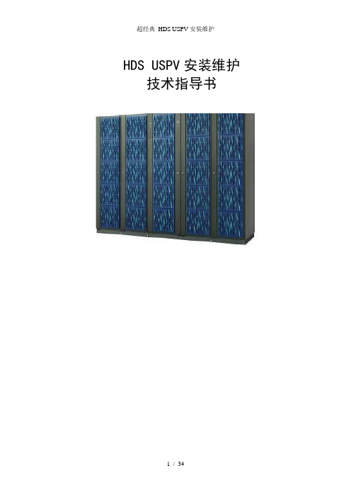
HDS USPV安装维护技术指导书目录1.背景情况 (3)1.1. 实施需求 (3)1.2. HDS USPV和Brocade交换机的详细配置 (3)2.实施前准备工作 (4)3.安装实施 (6)3.1. 物理安装 (6)3.2. SAN设计示意图 (7)3.3. USPV电源 (7)3.4. Brocade 48000的Extended Fabric Keys (7)3.5. USPV的端口设置 (8)3.6. LDEV对主机的分配(Mapping) (8)3.7. USPV安装实施详细步骤 (9)3.8. Brocade交换机的设置 (18)3.9. Brocade交换机的Zoning设置 (18)3.10. USPV磁盘阵列IP地址分配 (21)3.11. USPV磁盘阵列Hi-Track电话 (21)3.12. USPV磁盘阵列各软件缺省口令 (21)3.13. AIX 下HDLM软件的安装 (21)3.14. Linux 下HDLM软件的安装 (22)3.15. HP-UX下HDLM软件的安装 (22)4.日常维护和使用 (23)4.1. HDLM的软件常用命令 (23)4.2. 日常维护要求 (23)4.3. 故障信息的读取 (23)4.4. 连接新主机 (25)4.5. USPV的开机 (29)4.6. USPV的关机 (31)4.7. 异常掉电的处理 (34)USPV实施维护手册1.背景情况1.1.实施需求HDS的USPV磁盘阵列一台、2台Brocade48000光线导向器,该磁盘阵列计划连接IBM570、HP superdome server。
实施的主要内容是:●USPV和Brocade 48000的物理安装●USPV的RAID和LUN的设置●Brocade48000、Brocade48000安装、Zoning的设置,光纤联接●主机与存储的安装HDLM软件的安装●用户现场培训●维护文件档提交1.2.HDS USPV和Brocade交换机的详细配置2.实施前准备工作1)机房环境准备(提交机房环境要求)HDS TagmaStore USPV包含1个控制柜和0至4个扩展柜。
- 1、下载文档前请自行甄别文档内容的完整性,平台不提供额外的编辑、内容补充、找答案等附加服务。
- 2、"仅部分预览"的文档,不可在线预览部分如存在完整性等问题,可反馈申请退款(可完整预览的文档不适用该条件!)。
- 3、如文档侵犯您的权益,请联系客服反馈,我们会尽快为您处理(人工客服工作时间:9:00-18:30)。
1.登录SVP
2.修改模式到maintenance mode
3.进入maintenance
4.检查version 看版本中有无报警,注意pin不能闪,闪的话,说明有pending的数据没有
从Cache写到硬盘。
此时需要做DUMP 还要打电话到CALL Center
DUMP方法:AutoDump-》Detial->HDD->OK生成的文件在:C:\dkc200\tmp\hdcp.lzh
5.此时的界面中,闪烁的地方就是有问题的地方,如我们换硬盘,硬盘所在的DKU一定
会闪,点击,进入界面如下。
如果是更换其它的设备,界面如下图
6.我们选中相应的HDU界面如下
7.我们选中闪烁的磁盘,界面如下,这时可以从下图看到磁盘信息,我们点击Replace更
换磁盘。
Replace 之前建议去Information 中查看一下,LOG信息,在下面的16中会有介绍查看LOG的方法。
8.系统提示,是否更换磁盘,点击yes
9.系统会提示Blocking…. 锁定磁盘。
10.系统会提示Spinning down
11.系统会提示,检查磁盘的红灯是否亮起
12.系统提示,更换硬盘。
12.1 系统会提示插入软盘做DUMP
13.此时系统会从hot spare拷贝数据到新硬盘,在Device Status中可以看到拷贝的进度
14.拷贝结束后,我们确认Maintenance 中再无报警。
15.删除LOG信息
16.退出到SVP管理界面,选择infromation->Log…
选择SIM,点击List
选择Content 查看详细信息。
如无问题,即Complete.
这时会有三个消息,一个是坏盘的消息,一个是COPY START,一个是COPY Normal END。
