台达伺服电机-ASDA-B2系列样本
伺服驱动器-台达ASDA_B2系列

参数设 置
10 122 123 121 100 80 1 108 DO6+ 0ms 0ms
备注
P1-00 P2-10 P4-05
正负逻辑设置 伺服开启 JOG控制
002 1001双脉冲 101 0~5000
线色
红 白 黑 黄绿 黄色 蓝色
驱动器 侧 U V W PE N24 P24
六线 动力线
电机侧
1 2 4 5 3 6
四线
电机侧 1 2 3 4
线色
编码线
电机侧 驱动器侧
红
14
黑
45
棕 橙 屏蔽
78 8 6+7 9 外壳
电 L1C
L
源 输
L2C R
N L
入
S T
N
电 出源
输
U V W PE
红 白 黑 绿
台达伺服驱动器B2
CN1 I/O信号接线 PT控制模式
八芯线
脚号
功能
线色
备注
41
37 9 11+35 14+15 16 28 33 7
PULS 脉冲
SIGN 方向 ST 报警清除 SRDY
绿
绿白 蓝 红 黑 黑白 红白 蓝白 -
35需接P24 14需接N24
需接P24 需接N24 15需接N24 27需接N24
6需接N24
参数设置
参数序号
功能
P2-08 恢复出厂值 P2-15 EMGS 紧急停止 P2-16 NL 逆向运行禁止极限 P2-17 PL 正向运行禁止极限 P1-01 控制模式 P1-44 电子齿轮比分子 P1-45 电子齿轮比分母 P2-37=108 电磁刹车控制信号 P1-42 电磁刹车开启延时 P1-43 电磁刹车关闭延时
台达伺服手册

台達交流伺服系統ASDA-B2系列創變新未來為滿足泛用產業機械的功能需求,並大幅提升台達在中階伺服行業應用的優勢,台達機電事業群藉由技術的不斷突破,推出全新大作 ASDA-B2系列。
ASDA-B2 系列功率數由0.1kW 到3kW ,其優越的性能特點強調於「內建泛用機能應用,減少機電整合之變異成本」。
使用台達ASDA-B2系列產品時,除了可便利完成配線和操作設定,在與他牌產品更換過程中,馬達尺寸的對應性和產品特性的匹配,皆在水準之上。
ASDA-B2系列不僅滿足市場對於泛用產機的國產化設備需求,並且針對專用機提供多樣化的操作選擇。
高精度! 高應答! 優異的性價比!!!搬運機械放電加工機械裁切設備應用特色說明型號說明產品對應表配置與介面配線說明回生電阻表驅動器安規解釋驅動器標準規格驅動器外觀尺寸馬達標準規格馬達外觀尺寸T-N曲線配件配件選用表35679121213151923232733鋸床機械特色說明高性能精準定位控制的實現:■A SDA-B2系列支援20-bit 和 17-bit高解析編碼器,滿足機台設備高精度定位控制及平穩低速運轉的應用需求。
■高編碼器解析度可以降低頓扭矩的變動幅度, 提升馬達的高精準度。
原先2500 ppr 的頓扭矩波形新款17-bit 的頓扭矩波形■優異的高速性能表現:速度響應頻寬為550Hz,命令整定時間可達1ms以下。
■空載情況下,額定轉速-3000r/min 至 3000r/min 加速時間只需10ms。
此範例為60框號、400W馬達滿足多樣化的命令控制需求■內建位置、速度、扭力三種模式 (■可接受高速差動脈波命令 (4Mpps)■搭使運轉更平順亦更完整。
■提供前置摩擦力補償參數,針對循圓加工、Z軸動作,或是滾珠螺桿機構等應用,減輕控制器的負擔。
■提供防撞參數,針對棒材送料機等需要扭力控制應用之機台,可保護機構不易損壞。
提供客戶簡單導入伺服產品的選擇■ 動力線和編碼器接線與ASDA-B 系列共用,機種升級無須更換線材。
DELTA ASDA-B2系列 标准泛用型伺服驱动器 应用技术手册

Revision Oct, 2011
目錄
3.1.2 驅動器的連接器與端子 ............................................................... 3-3 3.1.3 電源接線法 .............................................................................. 3-4 3.1.4 馬達 U、V、W 引出線的連接頭規格 ............................................. 3-5 3.1.5 編碼器引出線的連接頭規格 ......................................................... 3-7 3.1.6 線材的選擇............................................................................... 3-11 3.2 伺服系統基本方塊圖 .......................................................................... 3-13 3.2.1 400W(含)以下機種(無內含回生電阻) .................................... 3-13 3.2.2 750W 機種(內含回生電阻,無風扇) .......................................... 3-14 3.2.3 1kW ~ 1.5kW 機種(內含回生電阻和風扇) .................................. 3-15 3.2.4 2kW ~ 3kW 機種(內含回生電阻和風扇) ..................................... 3-16 3.3 CN1 I/O 信號接線.............................................................................. 3-17 3.3.1 CN1 I/O 連接器端子 Layout......................................................... 3-17 3.3.2 CN1 I/O 連接器信號說明............................................................. 3-19 3.3.3 介面接線圖(CN1) .................................................................. 3-27 3.3.4 使用者指定 DI 與 DO 信號........................................................... 3-32 3.4 3.5 3.6 3.7 CN2 編碼器信號接線 ......................................................................... 3-33 CN3 通訊埠信號接線 ......................................................................... 3-36 CN5 類比電壓輸出端子 ...................................................................... 3-37 標準接線方式.................................................................................... 3-38 3.7.1 位置(PT)模式標準接線 ........................................................... 3-38 3.7.2 速度模式標準接線 ..................................................................... 3-39 3.7.3 扭矩模式標準接線 ..................................................................... 3-40
台达伺服手册
台達交流伺服系統ASDA-B2系列創變新未來為滿足泛用產業機械的功能需求,並大幅提升台達在中階伺服行業應用的優勢,台達機電事業群藉由技術的不斷突破,推出全新大作 ASDA-B2系列。
ASDA-B2 系列功率數由0.1kW 到3kW ,其優越的性能特點強調於「內建泛用機能應用,減少機電整合之變異成本」。
使用台達ASDA-B2系列產品時,除了可便利完成配線和操作設定,在與他牌產品更換過程中,馬達尺寸的對應性和產品特性的匹配,皆在水準之上。
ASDA-B2系列不僅滿足市場對於泛用產機的國產化設備需求,並且針對專用機提供多樣化的操作選擇。
高精度! 高應答! 優異的性價比!!!搬運機械放電加工機械裁切設備應用特色說明型號說明產品對應表配置與介面配線說明回生電阻表驅動器安規解釋驅動器標準規格驅動器外觀尺寸馬達標準規格馬達外觀尺寸T-N曲線配件配件選用表35679121213151923232733鋸床機械特色說明高性能精準定位控制的實現:■A SDA-B2系列支援20-bit 和 17-bit高解析編碼器,滿足機台設備高精度定位控制及平穩低速運轉的應用需求。
■高編碼器解析度可以降低頓扭矩的變動幅度, 提升馬達的高精準度。
原先2500 ppr 的頓扭矩波形新款17-bit 的頓扭矩波形■優異的高速性能表現:速度響應頻寬為550Hz,命令整定時間可達1ms以下。
■空載情況下,額定轉速-3000r/min 至 3000r/min 加速時間只需10ms。
此範例為60框號、400W馬達滿足多樣化的命令控制需求■內建位置、速度、扭力三種模式 (■可接受高速差動脈波命令 (4Mpps)■搭使運轉更平順亦更完整。
■提供前置摩擦力補償參數,針對循圓加工、Z軸動作,或是滾珠螺桿機構等應用,減輕控制器的負擔。
■提供防撞參數,針對棒材送料機等需要扭力控制應用之機台,可保護機構不易損壞。
提供客戶簡單導入伺服產品的選擇■ 動力線和編碼器接線與ASDA-B 系列共用,機種升級無須更換線材。
台达b2伺服说明书
台达b2伺服说明书篇一:台达B2伺服电机参数设定台达B2系列伺服电机参数设定自动:P0-02 驱动器状态显示参数功能:07 电机转速(r/min) P1-01控制模式及控制指令输入源设定参数功能:02 选择为S模式(r/min)P1-38 :零速度检出准位(低于设定速度无反馈) P1-40:仿真速度指令最大回转速度如果模式为S模式,则命令来源是V-REF,GND之间的模拟量电压差,输入的电压范围为-10v-10v(应该是0-10v吧,),电压对应的转速是由P1-40 调整的。
P1-55:最大速度限定值P1-40与P1-55设定的值一样。
P2-10:数字输入接脚DI1功能规划参数功能:10101:此信号接通时,伺服启动。
P2-11:数字输入脚DI2功能规划参数功能:10909:在速度及位置模式下,次信号接通,电机速度将被限制,限制的速1度指令为内部寄存器或仿真电压指令P2-12:数字输入接脚DI3功能规划参数功能:114P2-13: 数字输入接脚DI4功能规划参数功能:115P2-14: 数字输入接脚DI5功能规划参数功能:102 02:当伺服启动后,若没有异常发生,此信号输出信号P2-15: 数字输入接脚DI6功能规划参数功能:0P2-16: 数字输入接脚DI7功能规划参数功能:0P2-17: 数字输入接脚DI8功能规划参数功能:0000为设定输入点为常闭接点b。
手动设为001P2-18: 数字输出接脚DO1功能规划参数功能:102 02:当伺服启动后,若没有异常发生,此信号输出信号。
P2-19:103 03:当电机运行速度低于零速度(参数P1-38)的速度设定时,此信号输出信号。
P2-20: 数字输出接脚DO3功能规划参数功能:109P2-21: 数字输出接脚DO4功能规划参数功能:105P2-22: 数字输出接脚DO5功能规划参数功能:07 07:当伺服发生警示时,此信号输出信号。
篇二:台达PLC控制伺服ASDA说明台达ASDA伺服简单定位演示系统【控制要求】1:由台达PLC和台达伺服组成一个简单的定位控制演示系统。
Delta ASDA-B2 Series Servo Motors和Drives商品介绍说明书
Automation for a Changing WorldDelta AC Servo Drive & Motor ASDA-B2 SeriesHigh Precision. High Response. Cost Effective. Transporting and Conveying EquipmentElectric Discharge Machines (EDM)Cutting MachinesThe high-performance, cost-effective ASDA-B2 Series servo motors and drives meet the requirements for general-purpose machine control applications in the industrial automation market and enhance the competitive advantage of servo systems.The power rating of the ASDA-B2 Series ranges from 0.1kW to 3kW. The superior features of this series emphasize built-in motion control functions for general purpose applications and saving the cost of mechatronics integration. Delta's ASDA-B2 makes setting assembly, wiring, and operation convenient. In switching from other brands to Delta's ASDA-B2, the outstanding quality and features, and complete product lineup makes replacement simple and scalable. Customers that choose this value-based product gain noticeable competitive advantages in their market space. All of Delta's ASDA-B2 Series meet UL, cUL, CE, and RoHS standards.Sawing Machines2500ppr of Torque Ripple17-bit of Torque RippleExample: Frame size 60mm and 400W servo motor.►be controlled by internal parameters or analog voltage.) ►High-speed differential command (up to 4Mpps) forhigh precision positioning control.►Three notch filters are provided to suppress themechanical resonance efficiently and make the system operate more smoothly.►Lead friction compensation parameter is specified forthe application of circular interpolation, Z-axis motion and ball screw, and others to reduce the loading of the controller.►Product FeaturesImplements High Precision Positioning Control►ASDA-B2 Series servo drive supports 20-bit and 17-bit encoders. It satisfies the demand forhigh-precision positioning control and stable operation with lower speed. ►Applying the encoder with a higher resolution can reduce the cogging torque and improve themotor's precision.►Outstanding performance with higher speed: Up to 550Hz frequency response and settling time isbelow 1ms.►10ms acceleration time from -3000r/min to 3000r/min when running without a load.Offers Easy-To-Install Solution For Simple Start-UpSupports two analog outputsFulfills Easy-To-Use Requirements For Versatile Operation► O n-line monitoring function for 4 channels (similar to a digital oscilloscope) is available. The monitoring data can be 16-bit (4 channels) and 32-bit (2 channels).►Multi-functional parameter editor enablesusers to edit, modify, upload / download and print desired parameters in real time.Charge LEDLED DisplayPanel►ASDA-B Series share the same power cables andencoder cables for easy installation and setup without extra accessories.►Servo motor provides brake, oil seal, and other optionalconfigurations for different applications.►Separated power supply for main circuit and controlcircuit makes it easier to maintain the mechanism. ►400W or above servo drives have built-in regenerativeresistors, which simplify wiring and reduce the installation cost. ►Individual connectors (2 sets) for analog signal output,►User-friendly motor sizing software allows users to select the motor. ►ASDA-Soft configuration software (tuning software) is provided tomeet performance requirements quickly.►Easy-to-use digital keypad is ideal for setting parameters and enablesusers to directly monitor the servo drive and servo motor.►Specific software communication cable ASD-CNUS0A08 (Optional)can improve communication quality and convenience of operation. (please refer to optional accessories on page 28)Model Name ExplanationASDA-B2 Series Servo DrivesECMA Series Servo Motors1. Rated power of 100W to 1.5kW are marked number 21 with 220V, single-phase and three-phase connectionsProduct Line-upNote:1. (▄) in the model names represent shaft end / brake or the number of oil seals.2. (▲) in the model names represent encoder types (▲=1: Incremental encoder, 20-bit; ▲=2:Incremental encoder, 17-bit).LED Display■ T■A lit LED indicates that either power is connected to the servo drive or a residual charge is present■ U sed to connect 200~230 V AC , 50 / 60Hz commercial power supply.■ U sed to connect the servo motor. Never connect the output terminal to the main circuit power as the AC servo drive may be damaged beyond repair if incorrect cables are connected to the output terminals.■ U sed to connect 200~230 V AC , 50 / 60Hz single-phase or three-phaseV AC supply.■ F unction keys used to perform status display, monitor and diagnostic, function and parameter setting. Function Keys:MODE: Mode selectionSHIFT: For shifting the cursor to the left ▲: For increasing values ▼: For decreasing values SET: For storing dataPart Names and FunctionsCharge LED(R, S, T)Servo Motor Output (U, V, W)Regenerative ResistorGround TerminalOperation PanelControl Circuit Terminal (L1c, L2c)1. W hen using an external resistor, connect it toP ⊕and C, and ensure an open circuit between P ⊕and D.2.W hen using an internal resistor, ensure the circuit is closed between P ⊕and D, and the circuit is open between P ⊕and C3.W hen using external braking unit, connect braking unit to P ⊕and , and ensure an open circuit between P ⊕and D, and P ⊕and C .I/O Interface■U sed to connect Delta's DVP SeriesPLC or other external controllers forcontrolling I/O signals.Motor Encoder InterfaceSerial Communication PortAnalog Voltage Output TerminalHeatsinkReserved■U sed to connect the encoder.■U sed to connect PLC, HMI, andother controllers for RS - 485 /RS - 232 serial communication.■U sed to provide two analog monitoroutputs, MON1 and MON2.■U sed to secure servo drive and forheat dissipation.Please note that this only introduces a servo drive's basic functions.Specific models may have different functions.WiringPosition (Pt) Control Mode (for Pulse Command Input)EncoderWARNINGCaution: Do not use dual power supply. Failure to observe this caution may damage the servo drive.Speed (S) Control Mode50/60HzTwisted-pairor twisted-shield cableEncoderpulse outputNOTE:*1. 200W and below drives do not providebuilt-in regenerative resistor.*2. The brake coil has no polarity.*3. Please refer to SINK / SOURCE modesWiringTorque (T) Control ModeEncoderTwisted-pairor twisted-shield cableNOTE:*1. 200W and below drives do not providebuilt-in regenerative resistor.*2. The brake coil has no polarity.*3. Please refer to SINK / SOURCE modesSelection of Regenerative ResistorIEC: International Electrotechnical CommissionEN: Europaischen NormenEMC: Electromagnetic CompatibilityIP: Ingress Protection RatingsSpecificationsFootnote:*1. When it is in rated load, the speed ratio is: the minimum speed (smooth operation) / rated speed.*2. When the command is the rated speed, the velocity correction ratio is: (rotational speed with no load - rotational speed with full load) / rated speed.*3. TN system: The neutral point of the power system connects to the ground directly. The exposed metal components connect to the ground via the protective earth conductor.DimensionsASD-B2-0121ASD-B2-0221ASD-B2-0421( 100 W / 200 W / 400 W)1) Dimensions are in millimeters (inches); Weights are in kilograms (kg) and pounds (lbs).2) Dimensions and weights of the servo drive may be updated without prior notice.ASD-B2-0721(750W)1) Dimensions are in millimeters (inches); Weights are in kilograms (kg) and pounds (lbs).2) Dimensions and weights of the servo drive may be updated without prior notice.DimensionsASD-B2-1021ASD-B2-1521(1kW / 1.5kW)1) Dimensions are in millimeters (inches); Weights are in kilograms (kg) and pounds (lbs).2) Dimensions and weights of the servo drive may be updated without prior notice.ASD-B2-2023 ASD-B2-3023 (2kW/ 3kW)5.1) Dimensions are in millimeters (inches); Weights are in kilograms (kg) and pounds (lbs).2) Dimensions and weights of the servo drive may be updated without prior notice.Servo Motor Specifications Low Inertia SeriesServo Motor Specifications Medium / High Inertia SeriesServo Motor Specifications Medium high / High Inertia SeriesServo Motor Specifications High Inertia SeriesServo Motor DimensionsMotors - Frame Size 86mm and belowSpeed-Torque Curves (T-N Curves)1) Dimensions are in millimeters. Actual measured values are in metric units.2) Dimensions of the servo motor may be updated without prior notice.3) The boxes ( ) in the model names represent shaft end / brake or the number of oil seal.4) The boxes () in the model names represent encoder types (=1: Incremental encoder, 20-bit;=2: Incremental encoder, 17-bit).Torque (N-m)ECMA-C ▲0602□SECMA-C ▲0807□S ECMA-C ▲0807□HTorque (N-m)Torque (N-m)ECMA-C ▲0604□SECMA-C ▲0604□H ECMA-C ▲0804□7Torque (N-m)ECMA-C ▲0401□SECMA-C ▲0910□SECMA-C ▲0907□S2,0003,000Torque (N-m)Speed-Torque Curves (T-N Curves)Motors - Frame Size 100mm ~ 130mm1) Dimensions are in millimeters. Actual measured values are in metric units.2) Dimensions of the servo motor may be updated without prior notice.3) The boxes ( ) in the model names represent shaft end / brake or the number of oil seal.4) The boxes () in the model names represent encoder types (=1: Incremental encoder, 20-bit;=2: Incremental encoder, 17-bit).Torque (N-m)ECMA-E ▲1315□STorque (N-m)Speed (r/min)ECMA-C ▲1020□STorque (N-m)ECMA-C ▲1330□4Torque (N-m)ECMA-E ▲1305□STorque (N-m)ECMA-E ▲1310□SServo Motor DimensionsMotors - Frame Size 100mm ~ 130mmSpeed-Torque Curves (T-N Curves)ECMA-E ▲1320□S3) The boxes ( ) in the model names represent shaft end / brake or the number of oil seal.4) The boxes () in the model names represent encoder types (=1: Incremental encoder, 20-bit;=2: Incremental encoder, 17-bit).ECMA-F ▲1318□SECMA-F ▲1313□SECMA-G ▲1306□SECMA-G ▲1309□SECMA-F ▲1308□STorque (N-m)Torque (N-m)Torque (N-m)Torque (N-m)Torque (N-m)ECMA-G ▲1303□STorque (N-m)Motors - Frame Size 180mm28.659.556.40(67%)3,0002,00042.9714.329.59(67%)3,0003,0002,000ECMA-E ▲1820□S ECMA-E ▲1830□SECMA-F ▲1830□S ECMA-E ▲1835□S50.1316.7111.20Torque (N-m)Torque (N-m)Torque (N-m)Torque (N-m)57.29(300%)19.10(100%)9.55(50%)Optional AccessoriesPower Cables■3m and 5m standard cables are available.■I ndividual connectors are also provided for different demands.■T wo types are selectable: with brake and without brake.CN1 I/O Connectors■U sed to connect to external (host) controller ■D elta Part Number: ASDBCNDS0044CN1 Convenient Connector■D elta Part Number: ASD-IF-DS4444Encoder Cables■3m and 5m standard cables are available.■I ndividual connectors are also providedfor different demands.■T wo kinds of regenerative resistors areavailable, 400W / 40Ω and 1kW / 20Ω.Terminal Block Modules■0.5m connection cable is provided for saving oninstallation space.■ Delta Part Number: ASD-MDDS4444RS-485 Connectors■U sed to connect multiple ASDA Series productsby RS-485 interface through Modbus serialcommunication.■D elta Part Number: ASD-CNIE0B06ASD-Soft SoftwareCommunication Cables (for PC)■ Delta Part Number: ASD-CNUS0A08The figures are for illustration purposes only. Actual models maydiffer slightly in appearance from illustrations provided.Power ConnectorsASDBCAPW0000ASD-CAPW10003106A-20-18SASDBCAPW0100ASD-CAPW20003106A-24-11SPower CablesASDBCAPW0203/0205ASDBCAPW0303/0305Optional AccessoriesASD-CAPW2203/2205ASD-CAPW2303/23053106A-24-11SASDBCAPW1303/1305Power CablesASDBCAPW1203/1205KST: YF3.5-3SGEncoder CablesASDBCAEN1003/1005Optional AccessoriesEncoder ConnectorsASDBCAEN0000D-SUB Connector 9PASDBCAEN1000D-SUB Connector 9P3106A-20-29SASDBCAEN1000D-SUB 15 PIN PLUGI/O Signal ConnectorASD-BCNDS0044D-SUB 44 PIN PLUGRS-485 Connector Dimensions are in mmASD-CNIE0B06Voltage Output Cable (Analog Signal) Dimensions are in mm1) More accessories for ASDA-B2 will be on the list.2) Accessories images shown here may differ from the actual product.123Communication Cable between Drive and Computer (for PC) Dimensions are in mmASD-CNUS0A08Terminal Block Module Dimensions are in mmAccessories Combinations(X=3 indicates that the cable length is 3m; X=5 indicates that the cable length is 5m)(X=3 indicates that the cable length is 3m; X=5 indicates that the cable length is 5m)(X=3 indicates that the cable length is 3m; X=5 indicates that the cable length is 5m) 400W Servo Drive and 400W High Inertia Servo Motor(X=3 indicates that the cable length is 3m; X=5 indicates that the cable length is 5m)(X=3 indicates that the cable length is 3m; X=5 indicates that the cable length is 5m)(X=3 indicates that the cable length is 3m; X=5 indicates that the cable length is 5m)(X=3 indicates that the cable length is 3m; X=5 indicates that the cable length is 5m)(X=3 indicates that the cable length is 3m; X=5 indicates that the cable length is 5m)Accessories Combinations(X=3 indicates that the cable length is 3m; X=5 indicates that the cable length is 5m)(X=3 indicates that the cable length is 3m; X=5 indicates that the cable length is 5m) 1kW Servo Drive and 1kW Low Inertia Servo Motor(X=3 indicates that the cable length is 3m; X=5 indicates that the cable length is 5m)(X=3 indicates that the cable length is 3m; X=5 indicates that the cable length is 5m)(X=3 indicates that the cable length is 3m; X=5 indicates that the cable length is 5m)(X=3 indicates that the cable length is 3m; X=5 indicates that the cable length is 5m)(X=3 indicates that the cable length is 3m; X=5 indicates that the cable length is 5m)(X=3 indicates that the cable length is 3m; X=5 indicates that the cable length is 5m)Accessories Combinations(X=3 indicates that the cable length is 3m; X=5 indicates that the cable length is 5m)(X=3 indicates that the cable length is 3m; X=5 indicates that the cable length is 5m) 2kW Servo Drive and 1.3kW Medium High Inertia Servo Motor(X=3 indicates that the cable length is 3m; X=5 indicates that the cable length is 5m)(X=3 indicates that the cable length is 3m; X=5 indicates that the cable length is 5m)(X=3 indicates that the cable length is 3m; X=5 indicates that the cable length is 5m)(X=3 indicates that the cable length is 3m; X=5 indicates that the cable length is 5m)(X=3 indicates that the cable length is 3m; X=5 indicates that the cable length is 5m)(X=3 indicates that the cable length is 3m; X=5 indicates that the cable length is 5m)Industrial Automation Headquarters Delta Electronics, Inc.Taoyuan Technology CenterNo.18, Xinglong Rd., Taoyuan District,Taoyuan City 33068, TaiwanTEL: 886-3-362-6301 / FAX: 886-3-371-6301AsiaDelta Electronics (Shanghai) Co., Ltd.No.182 Minyu Rd., Pudong Shanghai, P.R.C.Post code : 201209TEL: 86-21-6872-3988 / FAX: 86-21-6872-3996Customer Service: 400-820-9595Delta Electronics (Japan), Inc.Tokyo OfficeIndustrial Automation Sales Department2-1-14 Shibadaimon, Minato-kuTokyo, Japan 105-0012TEL: 81-3-5733-1155 / FAX: 81-3-5733-1255Delta Electronics (Korea), Inc.Seoul Office1511, 219, Gasan Digital 1-Ro., Geumcheon-gu,Seoul, 08501 South KoreaTEL: 82-2-515-5305 / FAX: 82-2-515-5302Delta Energy Systems (Singapore) Pte Ltd.4 Kaki Bukit Avenue 1, #05-04, Singapore 417939TEL: 65-6747-5155 / FAX: 65-6744-9228Delta Electronics (India) Pvt. Ltd.Plot No.43, Sector 35, HSIIDC Gurgaon,PIN 122001, Haryana, IndiaTEL: 91-124-4874900 / FAX : 91-124-4874945Delta Electronics (Thailand) PCL.909 Soi 9, Moo 4, Bangpoo Industrial Estate (E.P.Z), Pattana 1 Rd., T.Phraksa, A.Muang,Samutprakarn 10280, ThailandTEL: 66-2709-2800 / FAX : 662-709-2827Delta Electronics (Australia) Pty Ltd.Unit 20-21/45 Normanby Rd., Notting Hill Vic 3168, Australia TEL: 61-3-9543-3720AmericasDelta Electronics (Americas) Ltd.Raleigh OfficeP.O. Box 12173, 5101 Davis Drive,Research Triangle Park, NC 27709, U.S.A.TEL: 1-919-767-3813 / FAX: 1-919-767-3969Delta Electronics BrazilSão Paulo Sales OfficeRua Itapeva, 26 - 3°, andar Edificio Itapeva,One - Bela Vista 01332-000 - São Paulo - SP - Brazil TEL: 55-12-3932-2300 / FAX: 55-12-3932-237Delta Electronics International Mexico S.A. de C.V. Mexico OfficeGustavo Baz No. 309 Edificio E PB 103Colonia La Loma, CP 54060Tlalnepantla, Estado de MéxicoTEL: 52-55-3603-9200 EMEAHeadquarters: Delta Electronics (Netherlands) B.V. Sales:*************************Marketing:***************************** TechnicalSupport:****************************** CustomerSupport:****************************Service:***************************TEL: +31(0)40 800 3900BENELUX: Delta Electronics (Netherlands) B.V.De Witbogt 20, 5652 AG Eindhoven, The NetherlandsMail:****************************TEL: +31(0)40 800 3900DACH: Delta Electronics (Netherlands) B.V.Coesterweg 45, D-59494 Soest, GermanyMail:*************************TEL: +49(0)2921 987 0France: Delta Electronics (France) S.A.ZI du bois Challand 2, 15 rue des Pyrénées,Lisses, 91090 Evry Cedex, FranceMail:***********************TEL: +33(0)1 69 77 82 60Iberia: Delta Electronics Solutions (Spain) S.L.UCtra. De Villaverde a Vallecas, 265 1º Dcha Ed.Hormigueras – P.I. de Vallecas 28031 MadridTEL: +34(0)91 223 74 20Carrer Llacuna 166, 08018 Barcelona, SpainMail:***************************Italy: Delta Electronics (Italy) S.r.l.Via Meda 2–22060 Novedrate(CO)Piazza Grazioli 18 00186 Roma ItalyMail:**************************TEL: +39 039 8900365Russia: Delta Energy System LLCVereyskaya Plaza II, office 112 Vereyskaya str.17 121357 Moscow RussiaMail:***********************TEL: +7 495 644 3240Turkey: Delta Greentech Elektronik San. Ltd. Sti. (Turkey) Şerifali Mah. Hendem Cad. Kule Sok. No:16-A34775 Ümraniye – İstanbulMail:***************************TEL: + 90 216 499 9910GCC: Delta Energy Systems AG (Dubai BR)P.O. Box 185668, Gate 7, 3rd Floor, Hamarain CentreDubai, United Arab EmiratesMail:************************TEL: +971(0)4 2690148Egypt + North Africa: Delta ElectronicsUnit 318, 3rd Floor, Trivium Business Complex, North 90 street, New Cairo, Cairo, EgyptMail:************************。
台达b2伺服说明书
台达b2伺服说明书篇一:台达B2伺服电机参数设定台达B2系列伺服电机参数设定自动:P0-02 驱动器状态显示参数功能:07 电机转速(r/min) P1-01控制模式及控制指令输入源设定参数功能:02 选择为S模式(r/min)P1-38 :零速度检出准位(低于设定速度无反馈) P1-40:仿真速度指令最大回转速度如果模式为S模式,则命令来源是V-REF,GND之间的模拟量电压差,输入的电压范围为-10v-10v(应该是0-10v吧,),电压对应的转速是由P1-40 调整的。
P1-55:最大速度限定值P1-40与P1-55设定的值一样。
P2-10:数字输入接脚DI1功能规划参数功能:10101:此信号接通时,伺服启动。
P2-11:数字输入脚DI2功能规划参数功能:10909:在速度及位置模式下,次信号接通,电机速度将被限制,限制的速1度指令为内部寄存器或仿真电压指令P2-12:数字输入接脚DI3功能规划参数功能:114P2-13: 数字输入接脚DI4功能规划参数功能:115P2-14: 数字输入接脚DI5功能规划参数功能:102 02:当伺服启动后,若没有异常发生,此信号输出信号P2-15: 数字输入接脚DI6功能规划参数功能:0P2-16: 数字输入接脚DI7功能规划参数功能:0P2-17: 数字输入接脚DI8功能规划参数功能:0000为设定输入点为常闭接点b。
手动设为001P2-18: 数字输出接脚DO1功能规划参数功能:102 02:当伺服启动后,若没有异常发生,此信号输出信号。
P2-19:103 03:当电机运行速度低于零速度(参数P1-38)的速度设定时,此信号输出信号。
P2-20: 数字输出接脚DO3功能规划参数功能:109P2-21: 数字输出接脚DO4功能规划参数功能:105P2-22: 数字输出接脚DO5功能规划参数功能:07 07:当伺服发生警示时,此信号输出信号。
篇二:台达PLC控制伺服ASDA说明台达ASDA伺服简单定位演示系统【控制要求】1:由台达PLC和台达伺服组成一个简单的定位控制演示系统。
台达B2 位置模式接线和参数设置
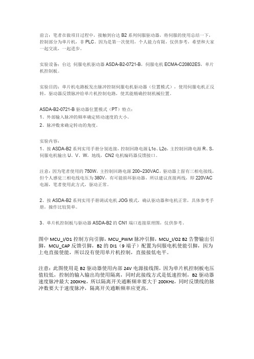
前言:笔者在做项目过程中,接触到台达B2系列伺服驱动器,将伺服的使用总结一下,控制部分为单片机,非PLC。
因为是第一次使用,个人能力有限,仅供参考,希望和大家一起交流,一起进步。
实验设备:台达伺服电机驱动器ASDA-B2-0721-B,伺服电机ECMA-C20802ES,单片机控制板。
实验目的:单片机电路板发出脉冲控制伺服电机驱动器(位置模式),使用伺服电机正反转,驱动器反馈脉冲给单片机控制电路,使其能精确控制机械位置。
ASDA-B2-0721-B驱动器位置模式(PT)特点:1、外部输入脉冲的频率确定转动速度的大小。
2、脉冲数来确定转动的角度。
实验内容:1、按ASDA-B2系列实用手册分别连接,控制回路电源L1c、L2c,主控制回路电源R、S,伺服电机输出U、V、W,地线,CN2电机编码器反馈接口。
注意:因为笔者使用的750W,主控制回路电源200~230VAC,驱动器上留有三相电接线,但个人感觉三相电线电压为380V,有可能损坏驱动器,所以建议直接两线,即220VAC 电源,笔者使用此方式,驱动正常。
2、按ASDA-B2系列实用手册调试电机JOG模式,确认驱动器和电机正常,具体参考手册,操作比较简单。
3、单片机控制板与驱动器ASDA-B2的CN1端口连接原理图,仅供参考。
图中MCU_I/O1控制方向引脚,MCU_PWM脉冲引脚,MCU_I/O2B2告警输出引脚,MCU_CAP反馈引脚,B2的DI1(9端子)配置为伺服电机使能引脚,因为上电直接使能,所以没有使用单片机控制,直接接低电平。
注意:此图使用是B2驱动器使用内部24V电源接线图,因为单片机控制板电压值较低,控制的输入输出均使用隔离,同时此接线方式是低速控制,B2驱动器速度脉冲最大200KHz,所以隔离开关通断频率要大于200KHz,同时反馈线的脉冲数要大于速度脉冲,隔离开关通断频率应更高。
图1控制板与伺服驱动器接线这里单单介绍的是I/O口的接线,具体电源接线,编码器,电机配线需要查阅相关的手册,这里不做过多介绍。