TXU-30操作手册_3.2.1_beta
串口Wifi模块-详细使用说明书【远嘉科技】

1 产品简介 • TLG10UA03 是华大电子推出的全新的第三代嵌入式 Uart-Wifi 模块产品。Uart-Wifi 是 基 于 Uart 接口的符合 wifi 无线网络标准的嵌入式模块,内置无线网络协议 IEEE802.11 协议栈 以及 TCP/IP 协议栈,能够实现用户串口数据到无线网络之间的转 换。通过 Uart-Wifi 模块, 传统的串口设备也能轻松接入无线网络。 • TLG10UA03 在前两代产品的基础上进行了全面的软硬件升级,功能更加强大,使用 更 加简单,其主要功能特性包括: 接口 • 双排插针式接口:HDR254M-2X4 支持波特率范围:1200~115200bps 支持硬件 RTS/CTS 流控 • 单 3.3V 供电 无线 • 支持 IEEE802.11b/g 无线标准 • 支持频率范围:2.412~2.484 GHz • 支持两种无线网络类型: • 基础网(Infra)和自组网(Adhoc) 支持多种安全认证机制: WEP64/WEP128/ TKIP/CCMP(AES) WEP/WPA-PSK/WPA2-PSK 支持快速联网 • 支持无线漫游 其它 • 支持多种网络协议: • TCP/UDP/ICMP/DHCP/DNS/HTTP 支持自动和命令两种工作模式 支持串口透明传输模式 支持 AT+控制指令集 支持多种参数配置方式: 串口/WEB 服务器/无线连接
• 6 AT+指令控制协议 6.1 语法说明 6.1.1语法格式 6.2 指令集 6.2.1指令列表 6.2.2网络控制类 6.2.3系统控制类 6.2.4参数设置类 6.3 例程代码 6.3.1例程代码说明 6.3.2命令模式下 Wifi 网卡的操作流程 6.3.3示例代码主要的数据结构 6.3.4串口数据操作 6.3.5AT 指令返回参数解析函数 6.3.6字符串操作函数 6.3.7几种 AT 指令发送解析示例 • 附录 A 常见问题与解答 Q1:模块为何搜索不到指定的网络? Q2:模块为什么连接不上网络? Q3:模块设置为 WPA/WPA2 安全模式时,为什么在复位后需要 10 多秒才能响应指令或自动连上网络? Q4:模块已经显示加网成功,为什么 PING 不通? Q5:自动工作模式下,为什么模块联网后总是一会儿能 PING通,一会儿又 PING不通? Q6:自动工作模式下,为什么模块复位后没有自动联网? Q7:自动工作模式下,为什么通过串口发送到模块的数据,延迟一段时间才被发送到网络上? Q8:自动工作模式下,输入逃逸字符后为什么无法退出透明传输状态? Q9:为什么配置程序搜索不到模块? Q10:使用配置程序修改参数,为什么返回使用了禁止的操作符错误? Q11:为什么打不开 WEB 服务器网页? Q12:用户设置了自身不支持的波特率,导致的再也无法连接模块该怎么办? Q13:无线连接时为什么搜索不到指定的模块? Q14:在我的使用环境下,为什么无线网络连接的质量总是很差? • 附录 B 文档修订记录
UP30飞控使用说明书

Garmin T-30D CAT III NAV Ramp Test Set 产品说明书

T-30D•Permits ICAO Annex 10 CAT III ILS ramp check certification• Checks VOR, GS, LOC, MB, Flight Director, andAutopilot• Dual VOR/LOC/GS frequencies • Separate and simultaneous MB/ILS • Dual extended-range variable ILS• Quick, easy one-man operation from the cockpit • Lightweight and portable – weighs only 18 lbs. • Built-in NICAD battery and charger• Two year limited warranty; five & ten year available • Rugged, reliable, affordable• Backed by 40 years manufacturing experience • CE Compliant• Available non standard VOR/ILS frequencies with local agency approvalThe T-30D Ramp Test Set is designed for one-man operation of the VOR, MB, GS, LOC, flight director, and autopilot from the cockpit or flight deck. Built into a rugged and durable case, the T-30D will permit compliance with CAT III periodic ramp check certification in all weather conditions.DescriptionSpecifications Subject to Change Copyright © Tel-Instruments Electronics Corp.1VOR• Allows selection of VOR bearing in 45º steps from 0 -315°• Manual slewing provides capability for checking full-scale deflection for “sticky” analog meter movement (+10º)• Permits deletion of the REF 0, VAR 0, 30 and 9960 Hz modulation to check flag operation • 1020 Hz tone enable switch • Manual slewing of VOR bearing ± 10° left and right of courseLOC and G/S• Allows selection of preset DDM deflections of: On Course, one and 2 dots off center• Full-scale deflection can be tested using manual slewing• Allows 90 and 150 Hz tones to be deleted • Simultaneous LOC/GS/MB Mode • 1020 Hz tone enable switch• Variable attenuator calibrated in 1 dB steps • Two preset paired frequencies availableMarker Beacon and ILS • User selection of inner, middle, and outer marker • Simultaneous MB and ILS output signals •Variable and Preset DDM settings • Variable attenuator to control output Additional Features• Rugged Mil-Spec case • Built in battery and charger• 100/220 volt operation 40 – 400 Hz• Simple to understand front panel and controls that requires minimal training • Built-In diagnostic Self Test/TIC-Tel-Instruments-T-30D-NAV-Ramp-Test-Set.aspxTo buy, sell, rent or trade-in this product please click on the link below:VOR Operation LOC Operation108.15 MHz ± 0.025%Frequency108.10 MHz ± 0.025%Power +17 ±2 dBAttenuation 110 dB in 1 dB stepsModulationAudio Frequency 90/150 HzAudio Frequency Accuracy ±0.01%AM Depth 20 ± 2%Distortion < 5%Phase Accuracy 90 to 1150 Hz ±10ºIndicator DeflectionOn Course0.0 ± 0.01DDM/0.155 ± .02DDMVariable -0.155 to +0.155 DDMStep Left and Right; 1 & 2 DotsTone 1020 Hz ± 2%108.05 MHz ± 0.025%Frequency108.00 MHz ± 0.025%Power +17/ ± 2 dBAttenuation 110 dB in 1 dB stepsModulationAudio Frequency 30/9960 HzAudio Frequency Accuracy ± 0.01%AM Depth 30 ± 2%FM Deviation 480 ± 30 HzDistortion < 5%Indicator Deflection/Bearing 0-315° /± 0.1º in 45°Steps/Variable ±10 º- 15°Tone 1020 Hz ± 2%Frequency 75.0 MHZ ± 0.005%Power +18 ± 2dBAttenuation 110 dB in 1 dB stepsModulationAudio Frequency 400/1300/3000 HzAudio Frequency Accuracy ± 2%AM Depth 95 ± 4%Distortion < 10%334.70 MHz ± 0.0025%Frequency334.55 MHz ± 0.0025%Power +11 ±2 dBAttenuation 110 dB in 1 dB stepsModulationAudio Frequency 90/150 HzAudio Frequency Accuracy ± 0.01%AM Depth 40 ± 3%Distortion < 5%Phase Accuracy 90 to 150 Hz ± 10ºIndicator DeflectionOn Course0.0 ± 0.01DDM/0.175 ± .025DDMVariable -0.175 to + 0.175 DDMStep Up and Down; 1 & 2 DotsDelete 90 and/or 150 HzSize 14.5 x 9.4 x 6.5 in.Weight 18lbs.PowerInternal Battery or external120/220 VAC 50-400 HzEnvironmentalStorage- -51° to + 71° COperating -30° to +55ºCT-30D Specifications Subject to Change Copyright © Tel-Instruments Electronics Corp. 2Tel-Instrument Electronics Corp.728 Garden StreetCarlstadt, NJ 07072(201) 933-1600MB OperationGS OperationPhysical CharacteristicsLeading the Avionics Test Industry into the 21st Century!。
TxRail-USB温度变送器0555 0035-01、0555 0035-02操作手册说明书

Operating ManualTxRail-USB Temperature Transmitter0555 0035-01 – 4-20 mA 0555 0035-02 – 0-10 VB+B Thermo-Technik GmbHContents 01Foreword (1)2General Advice (1)Labels (1)Warning Advice (1)Security Advices (2)3Introduction (3)4Technical Specifications (3)5Mechanical Installation (4)Öffnen des Messumformers (4)6Elektrical Installation (4)Recommendations for Installation (5)Electrical Connections (5)6.2.1Pt100 2-wires / NTC (5)6.2.2Pt100 3-wires (5)6.2.3Pt100 4-wires (5)6.2.4Thermoecouples and 0 – 50 mV (5)6.2.5Output (6)7Configuration (6)Software Configuration (7)Factory Settings (7)8Operation (7)9Questions? (8)1F OREWORDDear customer,We thank you for having purchased the TxRail-USB Temperature Transmitter and are very glad that you decided in favour of a product of B+B Thermo-Technik GmbH. We hope this product will fully satisfy you and will assist you effectively in your work.This Device has been developed to be technically highly up-to date. This product has been designed in accordance with the regnant European and German national directives and rules. For a proper and effective usage of the product the customer shall observe the following Operating Instructions. In the case that against one’s expectations any troubles occur which you cannot resolve yourself, please contact our service centers or your salesperson. We go after giving you rapid and competent help to minimize the risk of long-time outfalls.The following operating Instruction is an indispensable part of this Product. It contains important advices for the starting up and further use of the device2G ENERAL A DVICEThis documentation contains information which must be paid in attention to assure a highly effective and secure use of the supplied product Please read through the following instructions and make yourself familiar with the handling of the product before you insert it in your processes. Keep this document always readily to hand so you can consult it by need.LabelsAdviceIt is necessary to read the following advice before beginning the operations. Theused symbols in the manual acts first as eye catcher for security risks. Thesymbols do not replace the security advice. The text must be read to the endNecessary to observe This symbol designates important advice and tips that are necessary for thesuccess a work step. They must be followed to get good results Warning AdviceSecurity AdvicesB+B Thermo-Technik GmbH assume no liability for damages occurred through failure to observe these security advices. A usage non conform to the instructions given in this manual can damage the deviceBODY AND PROPERTY DAMAGESThe national and local standards for electrical installations must be se strictly observed.The use of the device is strictly reserved / restricted to properly schooled / qualified operators.The system is not adequate for use in atmosphere with explosion danger.Do not use the system in a high electric or magnetic field areaThe system must be operated only within the limits given in the technical DataExposing the system to hot temperatures (higher than the operating temperature) will cause damages in the electroniccircuits and also damage the housingUSAGE ACCORDING TO PURPOSEPlease use the product only for the purposes for which it is conceived. In case of doubt, please first contact B+B Thermo-Technik GmbHDISOPOSALPlease return the device to B+B Thermo-Technik GmbH after expiration of its lifetime..3I NTRODUCTIONThe TxRail-USB is an USB configurable DIN rail mount temperature transmitter. It allows selection and configuration of input type, measurement range, output type and calibration. Its output can be set to either loop powered 4-20 mA or 0-10 Vdc. Highly accurate and user-friendly, the TxRail-USB performs well from simple to sophisticated measurement applications.The output current or voltage is linearized according to the selected input sensor and adjusted to the configured range.4T ECHNICAL S PECIFICATIONSSensor InputUser defined. The supported sensors are listed in Table 1, along with their maximumranges.Maximal Voltage on the Sensor terminals 3 VThermocouples Type J, K, R, S, T, N, E and B, according to DIN EN 60584 (ITS-90). Impedance >> 1 MΩPt100Excitation 0.8 mA, α= 0.00385, according to DIN EN 60751 (ITS-90).For 2-wire sensors, terminals 3 and 4 must be short circuited.Pt1000Excitation 0.8 mA, α= 0.00385, according to DIN EN 60751 (ITS-90).For 2-wire sensors, terminals 3 and 4 must be short circuited.NTC R25°C10 kΩ ±1 %, B25/85 = 3435Voltage0 … 50 m VDC. Impedance >> 1 MΩSensor typeMaximal MinimalRange Linearisation spanSpannung0 … 50 mV 5 mVThermoelement K-150 … 1370 °C100 °CThermoelement J-100 … 760 °C100 °CThermoelement R-50 … 1760 °C400 °CThermoelement S-50 … 1760 °C400 °CThermoelement T-160 ... 400 °C100 °CThermoelement N-270 ... 1300 °C100 °CThermoelement E-90 ... 720 °C100 °CThermoelement B500 … 1820 °C400 °CPt100-200 ... 650 °C40 °CPt1000-200 ... 650 °C40 °CNTC-30 ... 120°C40 °CT ABELLE 1SUPPORTED S ENSORSTerms of reference Ambient 25 °C; Voltage: 24 VDC, Load: 250Ω; Setting time: 10 min Temperature effects < ±0,16 % / 25 °CSwitch-on delay typical 2,5 s . the accuracy is guaranteed only after 15 minutes Excitation Pt100, Pt1000, NTC800 µAWiring Pt100, Pt1000, NTC Maximal allowable cable resistance 25 ΩCable resistance effect 0,005°C / ΩAccuracySensor Typical Max.Pt100 / Pt1000 (-150 .. 400°C)0,10 % 0,12%Pt100 / Pt1000 (-200 .. 650°C)0,13 % 0,19%mV, K, J, T, E, N, R, S, B 0,1 % (*) 0,15 % (*)NTC 0,3 °C 0,7 °CT ABELLE 2Sensor accuracy(*) Add cold junction compensation: < ± 1 °CPower supply influence 0,006 % / V typical (% of FS ).Output 4-20 mA 4-20 mA or 20-4 mA, 2-wire, linear, proportional to the configured range0-10 V 0-10 VDC or 10-0 VDC linear, proportional to the configured range Resolution 4-20 mA 2 µA0-10 V 0,0025 V (12 bits)Power supply 4-20 mA Output 10 ... 35 VDC0-10 V Output 12 ... 35 VDCMaximal Load RL (max.) = (VDC – 10) / 0,02 [Ω]where VDC= Power supply (10-35V)Operating Temp. -40…85 °CHumidity 0...90 % RHEM Compatibility EN 61326-1:2006No electrical isolation between input and output.Internal protection against polarity inversionCold junction compensation for thermocouplesWires 0,14 …1,5 mm²Screw Tightening 0,8 Nm (empfohlen)Housing ABS UL94-HBCertificates CE5M ECHANICAL I NSTALLATIONThe TxRail-USB transmitter is suitable to be installed on 35 mmDIN rail. Vibrations, moisture and extreme temperatures, electro-magnetic interference, high voltage and other interferences canpermanently damage the unit, and could cause error in themeasured value AbmessungenÖffnen des MessumformersTo open the transmitter, you must press the orange lockerslocated on both sides of the enclosure and pull the frontal cover verycarefully, just like shown in Fig. 2.6E LEKTRICAL I NSTALLATION•Housing made of polyamide•Cable / wires: 0,14 … 1,5 mm ²A BBILDUNG 1DimensionsA BBILDUNG 2Opening the TransmitterA BBILDUNG 4•Recommended torque fort he connection screws: 0.8 NmRecommendations for Installation• Conductors of small electrical signals must be distant from Power supply and high-tension/current conductors, preferably passing through grounded conduits.• A specific electrical power supply network should be provided for instruments use only• In controlling and monitoring applications, possible consequences of any system failure must be considered in advance. •RC filters (47R an 100nF, serial) in inductor charges (contactors, solenoids, etc.) are recommendedElectrical ConnectionsThe figures below show the electrical connections required. The terminals 1, 2, 3 and 4 are dedicated to the sensor connection. LOAD represents the 4-20 mA current or 0-10 V voltage measuring device (indicator, controller, recorder, etc.).6.2.1 Pt100 2-wires / NTCNote : When the Pt100/Pt1000 2-wire the terminals 1 and 3 must be interconnected, according to the figure below. To use the Pt100/Pt1000 2-wire, you must configure thePt100/Pt1000 3-wire option in TxConfig II. The Pt100/Pt1000 wire length should be less than 30 cm tomaintain the measurement error within specifications (electrical resistance).6.2.2 Pt100 3-wires6.2.3 Pt100 4-wiresPt100 3 and 4-wire : For appropriate cable resistance compensation they should be equal for all legs. Maximum wire resistance is 25 Ω per wire leg. Usage of a 3 or 4 wire with conductors of equal length and gauge is recommended.6.2.4 Thermoecouples and 0 – 50 mVA BBILDUNG 3A BBILDUNG 56.2.5 Output7 C ONFIGURATIONChanges to the configuration are possible through the TxConfig II software, provided free of charge. The transmitter configuration interface (USB cable) can be purchased from the manufacturer or its authorized sales representatives.The TxConfig II software is continuously updated, and new versions can be downloaded at no charge from the manufacturer’s website. To install, execute the TxConfigIISetup.exe file and follow the instructions.During the setup, the transmitter is powered by the USB, not requiring an external power supply. The transmitter setup can also be made by connecting it to the loop, using the loop power supply. There is no electrical insulation between the transmitter and the communication port (interface), therefore it is not recommended to configure it with the sensor inlet connected to the process. See Fig. 2After these connections, the user must run the TxConfig II software and, if necessary, consult the Help topic to help using the software .The USB communication port (interface) of the TxBlock-USB is not electrically insulated from the transmitter’s input.A BBILDUNG 7A BBILDUNG 8 Strom (rechts) - Spannung (links)A BBILDUNG 9 USB cable connectionSoftware ConfigurationThe fields in the screen mean:1. General Information : This field shows information that identifying the transmitter. This information should be sent to the manufacturerin an eventual request for technical assistance.2. Sensor : Select the type of sensor to be used. See Table 1.3. Measuring Range : Sets de measurement range of the transmitter.a. Lower Range Limit : Desired temperature for minimum retransmission value.b. Upper Range Limit : Desired temperature for maximum retransmission value.c. Sensor Range The values chosen cannot exceed the range of sensor shown in this field. See Table 1 of this manual.d. Minimum Range Do not set a lower band (span) that the Minimum Range indicated below in this same field. See Table 1 ofthis manual.4. Sensor Failure : It establishes the output behavior, when the transmitter indicates a failure:a. Minimum : output current goes to < 3.8 mA or output voltage is 0 V (down-scale), typically used for refrigeration.b. Maximum : output current goes to > 20.5 mA or output voltage is 10 V (up-scale), typically used for heating.5. Zero Correction : It corrects small deviations presented in the transmitter output, for example, when the sensor is replaced.6. Send Configuration : It applies the new setup. Once sent, the setup will be immediately adopted by the transmitter.7. Read Configuration : Reads the current setup in the transmitter connected. The screen now presents the current setup that may bechanged by the user.Factory SettingsSensor: Pt100 3-wire, range 0 to 100 °C Sensor failure: upscale (maximum). 0 °C zero correction. Unit: °C;Output: 4-20 mA.8 O PERATIONThe sensor offset can be changed through the TxConfig II software. The USB cable may be connected to the transmitter without causingA BBILDUNG 10 Hauptfenster TxConfig IIany measurement errors. See item Zero Correction in the chapter CONFIGURATION of this manual.The user must choose the most suitable sensor and range to the process. The chosen range must not exceed the maximum range of measurement defined for the sensor and should not be smaller than the minimum range for the same sensor.It is important to note that the transmitter accuracy is based on the maximum range of the sensor used, even when a narrowerrange is programmed. Example:The Pt100 sensor in the range 0 to 100 °C and accuracy of 0.12 %, the maximum error will be 1.02 °C (0.12 % de 850 °C).The Pt100 sensor in the range 500 to 600 °C and accuracy of 0.19 %, the maximum error will be 1.61 °C (0.19 % of the 850 °C).Note: When measurements are made at the transmitter, see if the Pt100 excitation current required by the calibrator is compatible with the Pt100 excitation current used in the transmitter: 0.8 mA9Q UESTIONS?For further Information about this or other products of B+B Thermo-Technik GmbH please do not hesitate to contact us at: B+B Thermo-Technik GmbHHeinrich-Hertz-Straße 478166 DonaueschingenDeutschlandTel.: +49 771 83160Fax: +49 771 831650E-Mail:*******************。
中海达V30+GNSS+RTK系统使用说明书+1.0版(201202)
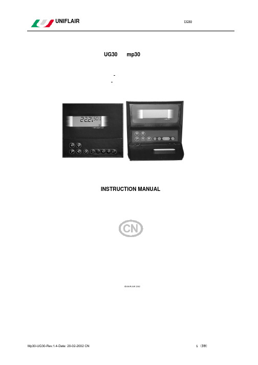
优力空调操作手册UG30
数字输入–接线头 2 配 10 个 24Vac 数字输入
CW – CW/S ID1 遥控 开 / 关 ID2 气流开关 ID3 过滤器堵塞开关
(CW/S 机组为标准,CW 机组为选项) ID4 电加热器过热保护 ID5 外部温湿度传感器和漏水传感器(选项)报警 ID6 加湿器报警 ID7 --ID8 --ID9 ---
CW – CW/S
DX-DX/S
B1 室内温度 B2 外部温度 – 夏/冬季转换
室内温度 外部温度 – 夏/冬季转换
B3 室内相对湿度
室内相对湿度
B4 STM 送风温度 GND 逻辑输入公共点
STM 送风温度
+V 探头 14Vdc (最大 30mA)的电源输入
数字输出 配有 7 个数字输出:包括 1 个 200 Vac 交流继电器,1 个 200 Vac 常开继电器
UNIFLAIR
UG30 控制器使用手册
UG30 和 mp30 控制器
恒温恒湿精密空调机组
- 冷冻水机组 - 直接膨胀机组
INSTRUCTION MANUAL
使用手册
Mp30-UG30-Rev.1.4-Date: 20-02-2002 CN
1 (39)
UNIFLAIR
UG30 控制器使用手册
关于软件
显示器能显示机组的运行状态和主要参数,用符号和数字及字母组成:
1, 2….
传感器参数
r1,r2…..
调节参数
C9, CA….
压缩机参数
F9, FA…..
风扇参数
P1,P2…..
报警参数
H1,H2….
常用格式化参数
所有控制参数在出厂前已根据具体机组类型设置好;已编定的程序会因硬件键或串行线受影响。如更改
TG30 电线跟踪器用户手册说明书

User's GuideWire Tracer KitModel TG30IntroductionCongratulations on your purchase of Extech’s Model TG30. This transmitter and probe kit isused to quickly trace and identify cables or wires within a group and also check the operationof phone lines. With proper use and care, this meter will provide many years of reliableservice.SpecificationsPower Transmitter; 9V NEDA 1604/1604ALProbe; (4) LR44, 157, AG13, A76 or equivalentOperating Temperature 14 to 122o F (-100 to 50o C)Operating Humidity <80% RHAltitude 2000metersDimensions Probe:5.8x1.1x1.1(147x28x28mm),Transmitter:2.6x4.1x0.9”(67x103x23mm) Weight Probe 1.1oz(30g); Transmitter 4.2oz(120g)Meter DescriptionTransmitter1. Function switch (OFF/T.L., Tx,CONT)led2. Continuity3. Telephone Line ledled4. Power5. Battery compartment (rear)6. ModularconnectorsProbe1. Signal2. PowerLED3. Sensitivity4. Powerclip5. Pocketcompartment6. Battery7. SpeakerAdaptor1. RJ11 socket (connect to transmitter modularconnector)2. CATV Type F connectorclips3. AlligatorOperating InstructionsCAUTION: Always test the probe and transmitter for proper operation before use.CAUTION: The transmitter is not designed for use on energized circuits. Connecting to any voltage source greater than 52VDC may damage the circuit.Note: The transmitter will not generate a signal into a short circuit.Self Test1. Set the transmitter power switch to the Txposition.2. Adjust the probe sensitivity to MAX (+)clockwise position.3. Press and hold the probe power button.The red LED will light.4. Move the probe close to the transmittercable and note that the audible trace toneand sensitivity adjustment perform normally.Cable/Wire tracing1. Select the transmitter termination required. Permanently attached are RJ11 and RJ45connectors. Plug the RJ45 connector into the adaptor cable to obtain CATV type Fconnection or alligator connectors.2. Connect the transmitter to the cablea) For cables terminated at one end, connect the red alligator clip to a wire and theblack alligator clip to equipment groundb) For unterminated cables, connect the red alligator clip to one wire and the blackalligator clip to another wire.c) For cables with modular connectors, plug the RJ11, RJ45 or type F connectorsdirectly into the mating cable connectors.3. Set the transmitter power switch to the Tx position.4. Adjust the probe sensitivity to MAX (+) clockwise position.5. Press and hold the probe power button. The red LED will light.6. Hold the insulated probe tip against the wire in question to pick up the signalgenerated by the transmitter.7. Rotate the volume/sensitivity control on the top of the probe for the appropriate leveland sensitivity to identify and trace the wire.8. The tone will be the loudest on the wires directly connected to the transmitter. Telephone Line Test1. Switch the transmitter to the OFF position2. Insert the modular plug into the phone line.3. Observe the “TEL. LINE” LED for the following conditions;a. Bright Green:Working line, not in use, correct polarityb. Dim Green or Red: Working line, not in use, polarity undeterminedc. Bright Red: Working line, not in use, reverse polarityd. Bright Green/Red flashing: Working, ringing linee. No light: Open pair, no serviceContinuity Test1.2.Battery replacementProbe:Install new batteries by turning the speakerand pocket clip ¼ turn to the left, removethe battery door and replace the four LR44batteries. Observe battery polarity. Transmitter:Remove the rear battery compartment door and replace the 9V battery.WarrantyEXTECH INSTRUMENTS CORPORATION warrants this instrument to be free of defects in parts andworkmanship for one year from date of shipment (a six month limited warranty applies on sensors and cables). If it should become necessary to return the instrument for service during or beyond the warranty period, contact the Customer Service Department at (781) 890-7440 ext. 210 for authorization. A Return Authorization (RA) number must be issued before any product is returned to Extech. The sender is responsible for shipping charges, freight, insurance and proper packaging to prevent damage in transit. This warranty does not apply to defects resulting from action of the user such as misuse, improper wiring, operation outside of specification, improper maintenance or repair, or unauthorized modification. Extech specifically disclaims any implied warranties or merchantability or fitness for a specific purpose and will not be liable for any direct, indirect, incidental or consequential damages. Extech's total liability is limited to repair or replacement of the product. The warranty set forth above is inclusive and no other warranty, whether written or oral, is expressed or implied.Copyright © 2002 Extech Instruments Corporation. All rights reservedincluding the right of reproduction in whole or in part in any form.。
TX3201输入模块安装使用说明书

一、概述TX3201输入模块(以下简称模块)符合国家标准GB16806-2006《消防联动控制系统》。
本模块用于监视主动型消防设备(如:水流指示器、压力开关等)的工作状态,并将所监视设备的动作信号通过总线传送给火灾报警控制器。
本模块外形美观,采用插拔式结构,方便施工安装;采用专用集成芯片,具有强大的分析判断能力,可对所监视设备的断路状态、短路状态进行检测,并通过指示灯给出状态指示。
注意:在输入线的末端(远离模块端)必须并联一个10KΩ的终端电阻,否则控制器将报该模块的“反馈线故障”。
二、特点1.二总线,无极性2.内置专用集成芯片3.总线与输入线采用隔离设计,减少外部干扰的影响4.输入可设置为常开或常闭模式5.软硬件多级滤波,提高抗干扰能力6.插拔式结构,方便施工安装三、技术参数1.总线协议:T3协议2.工作电压:总线电压:15~28V(脉冲电压)3.工作电流:总线监视电流:≤0.4mA总线动作电流:≤1.0mA4.指示灯:输入指示灯:红色(正常监视状态闪亮一次,故障状态闪亮两次,动作状态常亮)5.编码方式:电子编码(占一个总线地址点,编码范围在1~242之间任意设定)6.终端电阻:10KΩ7.线制:与火灾报警控制器采用无极性二总线连接8.使用环境:温度:-10℃~55℃相对湿度:≤95%RH,不凝露9.外形尺寸:86mm×86mm×33mm(含底座)10.重量:约85g(含底座)11.执行标准:GB16806-2006四、结构特征和工作原理1.模块的外形尺寸及安装尺寸如图1所示(单位:mm)。
图1外形尺寸及安装尺寸示意图2.工作原理模块内置专用集成芯片,负责监视主动型消防设备(如:水流指示器、压力开关等)的工作状态,并分别以正常、动作、故障三种形式上传给火灾报警控制器。
五、安装与布线警示:◆安装模块之前,必须切断回路的电源并确认底座已安装牢靠,且连接线准确无误。
◆在输入线的末端(远离模块端)必须并联一个10KΩ的终端电阻(具体接线方法参见图3)。
V8多功能电法仪施工简明手册_3.4.7_beta - 副本

对于不同的地球物理方法,您需要在计算机上安装一些软件,并确认您的 V8 System 系统各组件已经安装了相应方法的数据采集模块。您可以参考表 2.1 和表 2.2 进行 软件安装。
方法 MT/AMT CSAMT
SIP TDEM TDIP
表 2.1 各种地球物理方法需要的功能模块及需安装的软件
需要的模块
需安装的软件
软件说明
MT/AMT‐DA (V8) MT/AMT‐DX (RXU‐3E)
CMT‐DA (V8) CMT‐DX (RXU‐3E/TM)
SIP‐DA (V8) SIP‐DX (RXU‐3E/TM)
TEM‐DA (V8) TEM‐DX (RXU‐TM)
TIP‐DA (V8) TIP‐DX (RXU‐3E/TM)
图 1.3 左:非 MT/AMT 的数据文件 右:AMT 的数据文件
请注意,开机时严禁插拔 CF 卡,否则对系统的软硬件会造成一些不可预料的损坏。 有关数据文件的命名方式,请您参考英文文档及翻译版。
4
第二章 V8 System 的一般施工流程
在实际生产中,对于不同的地球物理方法,在施工之前你都必须清点软、硬件设备是 否齐全,设置好一个通用的工作参数表,设备进场后,最好进行标定(参考第八章)确定 设备正常。正常生产后每天应该对当天的数据进行数据处理。
简介
自 1980 年的 MT‐16 系列产品以来(第三代产品),凤凰公司的地球物理电磁法观测系 统一直处于世界领先地位。
在 20 世纪 50 年代法国的 Cagniard 和俄国的 Tikhonov 开发 MT 法并使用一些设备开始 进行类似数据观测的时候,凤凰公司开发了第一代大地电磁观测系统,那个时候大量的数 据处理还必须手工计算。60 年代中期凤凰公司推出了采用微型计算机处理、磁带记录的车 载第二代观测系统。自凤凰公司进入世界市场以来,后来的几代产品不断增强了数据计算 能力、增大一次观测的道数、远程无线通讯能力、GPS 卫星同步技术。同时,凤凰公司不 断推出减少成本、增加效率的地球物理电磁观测方法。
Omega TX31 热敏电导线2线头戴式传输器用户指南说明书
e-mail:**************For latest product manuals:TX31Thermocouple Input 2-WireHead-Mounted TransmitterShop online atUser’s GuideMADE IN T AIWANThermocouple Input2-Wire Head-Mounted Transmitter Model TX31Cold- junction compensation Multi-range selectable Galvanic isolation Long term stability Competitive pricing DescriptionsThe Model TX31 is an analog, isolated 2-wire head-mounted temperature transmitter that converter the thermocouple input into a proportional to the voltage generated by the thermocouple sensor, linear, and highly accurate 4- 20 mA output current in a varietyapplications such as process control, automation system, and energy source management.The TX31 is performed by means of a 3 DIP-switch array for coarse range setting, and two multi-turn potentiometers (ZERO & SPAN) which are used for the final fine-tuning. The unit is housed in a metal enclosure with a plastic top cover, fitting into DIN B connection heads providing excellent RFI immunity.The TX31 accepts low level signal from thermocouple,filtered, amplified, and converter to process current to reduce susceptibility transients and noise operations and allow the same two wires to carry the transmitter power and output current signal simultaneously.Specifications(Vloop = 24 VDC, Tamb = 23 ± 2 deg C , Rload = 250 ohms)Output: 4 - 20 mA; Upscale < 26 mA when T/C wire broken Loop power: 12 - 32 Vdc. Reverse polarity protected,LED on indication Input thermocouple: J; E; K; T; R; S; B; N Supply voltage effect: ± 0.01%/V Temperature coefficient: ± 0.02% /¢J (T amb = 5 to 50 deg C )Repeatability: ± 0.01% of voltage input spanLinearity error: ± 0.1 % of voltage input span ( not temperature input)Galvanic isolation: input/output 1000 Vrms, continuous Cold-junction compensation: ± 2 ¢J max. (T amb = 5 to 50 deg C )Load capability: 50 x (loop power - 12) ohms Fine adjustment: 5 % of ZERO & SPAN RFI effect (5W, 470 MHz): < ± 10% of span Response time (0 to 90%): 200 msHousing material: Cast Aluminum with epoxy coating and Polycarbonate, UL94-V0 gradeConnection: M3 Screw, nickel coated brass; AWG 12- 22Operation environment: - 20 to 70 ¢J ; 5 to 85 %, non-condensing Dimensions: 45mm DIA. x 27mm H Weight: 65 gOMEGA ENGINEERING, INC.Table 1 Switch settings for SpanAdjustmentsConnect signal source (calibrator) to the unit, power on warm up 10 minutes.A .Set the calibrator to the desired low temperature (4 mA point) and adjust the potentiometer ZERO to get Iout = 4.00 mA.B. Set the calibrator to the desired high temperature (20 mA point) and adjust the potentiometer SPAN to get Iout = 20.00 mA .C. Repeats steps A & B once, if necessary for best accuracyWiring Connections Dimensions mm(inch )NOTE:When change span by dip switch, the transmitter will be calibrated again for best accuracy H=27Note:The DIP-switch is protected by a small tip which has to be moved before settingIt is the policy of OMEGA Engineering, Inc. to comply with all worldwide safety and EMC/EMI regulations that apply. OMEGA is constantly pursuing certification of its prod-ucts to the European New Approach Directives. OMEGA will add the CE mark to every appropriate device upon certification.The information contained in this document is believed to be correct, but OMEGA accepts no liability for any errors it contains, and reserves the right to alter specifications without notice. WARN-ING: These products are not designed for use in, and should not be used for, human applications.WARRANTY/DISCLAIMEROMEGA ENGINEERING, INC. warrants this unit to be free of defects in materials and workmanship for a period of 13 months from date of purchase.OMEGA’s WARRANT Y adds an additional one (1) month grace period to the normal one (1) year product warranty to cover handling and shipping time. This ensures that OMEGA’s customers receive maximum coverage on each product.If the unit malfunctions, it must be returned to the factory for evaluation. OMEGA’s Customer Service Department will issue an Authorized Return (AR)number immediately upon phone or written request. Upon examination by OMEGA, if the unit is found to be defective, it will be repaired or replaced at no charge. OMEGA’s WARRANTY does not apply to defects resulting from any action of the purchaser, including but not limited to mishandling,improper interfacing, operation outside of design limits, improper repair, or unauthorized modification. This WARRANTY is VOID if the unit shows evi-dence of having been tampered with or shows evidence of having been damaged as a result of excessive corrosion; or current, heat, moisture or vibra-tion; improper specification; misapplication; misuse or other operating conditions outside of OMEGA’s control. Components in which wear is not warranted, include but are not limited to contact points, fuses, and triacs.OMEGA is pleased to offer suggestions on the use of its various products. However, OMEGA neither assumes responsibility for any omis-sions or errors nor assumes liability for any damages that result from the use of its products in accordance with information provided by OMEGA, either verbal or written. OMEGA warrants only that the parts manufactured by the company will be as specified and free of defects. OMEGA MAKES NO OTHER W ARRANTIES OR REPRESENTATIONS OF ANY KIND W HATSOEVER, EXPRESSED OR IMPLIED,EXCEPT THAT OF TITLE, AND ALL IMPLIED WARRANTIES INCLUDING ANY WARRANTY OF MERCHANTABILITY AND FITNESS FOR A PAR-TICULAR PURPOSE ARE HEREBY DISCLAIMED. LIMITATION OF LIABILITY: The remedies of purchaser set forth herein are exclusive, and the total liability of OMEGA with respect to this order, whether based on contract, warranty, negligence, indemnification, strict liability or other-wise, shall not exceed the purchase price of the component upon which liability is based. In no event shall OMEGA be liable for consequen-tial, incidental or special damages.CONDITIONS: Equipment sold by OMEGA is not intended to be used, nor shall it be used: (1) as a “Basic Component” under 10 CFR 21 (NRC), used in or with any nuclear installation or activity; or (2) in medical applications or used on humans. Should any Product(s) be used in or with any nuclear installation or activity, medical application, used on humans, or misused in any way, OMEGA assumes no responsibility as set forth in our basic WARRANT Y/DISCLAIMER language, and, additionally, purchaser will indemnify OMEGA and hold OMEGA harmless from any liability or damage whatsoever arising out of the use of the Product(s) in such a manner.Servicing North America:U.S.A.:One Omega Drive, Box 4047ISO 9001 CertifiedStamford, CT 06907-0047Tel: (203) 359-1660FAX: (203) 359-7700e-mail:**************Canada:976 BergarLaval (Quebec) H7L 5A1, Canada Tel: (514) 856-6928FAX: (514) 856-6886e-mail:*************For immediate technical or application assistance:U.S.A. and Canada:Sales Service: 1-800-826-6342/1-800-TC-OMEGA ®Customer Service: 1-800-622-2378/1-800-622-BEST ®Engineering Service: 1-800-872-9436/1-800-USA-WHEN ®Mexico:En Espan ˜ol: (001) 203-359-7803FAX: (001) 203-359-7807e-mail:*******************************.mxOMEGAnet ®Online Service Internet e-mail***********************Servicing Europe:Czech Republic:Frystatska 184, 733 01 Karviná, Czech Republic Tel: +420 (0)59 6311899FAX: +420 (0)59 6311114Toll Free: 0800-1-66342e-mail:*****************Germany/Austria:Daimlerstrasse 26, D-75392 Deckenpfronn, GermanyTel: +49 (0)7056 9398-0FAX: +49 (0)7056 9398-29TollFreeinGermany************e-mail:*************United Kingdom:One Omega Drive, River Bend Technology CentreISO 9002 CertifiedNorthbank, Irlam, Manchester M44 5BD United Kingdom Tel: +44 (0)161 777 6611FAX: +44 (0)161 777 6622Toll Free in United Kingdom: 0800-488-488e-mail:**************.ukRETURN REQUESTS /INQUIRIESDirect all warranty and repair requests/inquiries to the OMEGA Customer Service Department. BEFORE RET URNING ANY PRODUCT (S) T O OMEGA, PURCHASER MUST OBTAIN AN AUTHORIZED RETURN (AR) NUMBER FROM OMEGA’S CUSTOMER SERVICE DEPARTMENT (IN ORDER T O AVOID PROCESSING DELAYS). T he assigned AR number should then be marked on the outside of the return package and on any correspondence.The purchaser is responsible for shipping charges, freight, insurance and proper packaging to prevent breakage in transit.FOR WARRANTY RETURNS, please have the following information available BEFORE contacting OMEGA:1.Purchase Order number under which the product was PURCHASED,2.Model and serial number of the product under warranty, and3.Repair instructions and/or specific problems relative to the product.FOR NON-WARRANTY REPAIRS,consult OMEGA for current repair charges.Have the following information available BEFORE contacting OMEGA:1. Purchase Order number to cover the COST of the repair,2.Model and serial number of the product, and3.Repair instructions and/or specific problems relative to the product.OMEGA’s policy is to make running changes, not model changes, whenever an improvement is possible. T his affords our customers the latest in technology and engineering. OMEGA is a registered trademark of OMEGA ENGINEERING, INC.© Copyright 2007 OMEGA ENGINEERING, INC. All rights reserved. This document may not be copied, photocopied, reproduced, translated, or reduced to any electronic medium or machine-readable form, in whole or in part, without the prior written consent of OMEGA ENGINEERING, INC.M4411/0107。
拓洋T-UV2专业版功能操作步骤

拓洋T-UV2专业版对讲机功能操作步骤手动输入频点操作:1、无哑音频道1:按VFO键切换到频率模式,然后输入445.325,在按MENU键,在按25,在按MENU键,在按上下键选择没有CH开头的例如001,在按MENU键储存,在按exit键退出,按VFO键切换到信道模式频点就不会改动。
2、有哑音频道2:按VFO键切换到频率模式,然后输入440.025,按MENU键,按25,在按MENU键,在按上下键调为002,在按MENU键,在按exit。
按MENU键,在按数字14,在按MENU键,在按上下键选择71.9,在按MENU键设置好频点之后,可以互通对讲,按MENU键输入25,进入储存,按MENU确认,选择没有CH开头,按上下键选择所要储存的频道,例如025,按MENU键确定,按exit键退出,按VFO键切换到信道模式频点就不会改动。
自动扫描频点操作:1.扫描频点:按MENU键在按18键,按MENU键在按上下选择SE模式,在按VFO却换到频率模式,输入400.000在长按*号键开始扫描对方频点,对方要长按发射键扫描到频点,要多扫描几次。
2.扫描亚音:按MENU键在按14键,在按MENU在按上下选择亚音67在长按*号键对方的对讲机在长按发射键开始扫描。
扫出正确的频点和哑音后,按MENU键在按25键在按上下选择键选择没有CH开头的例如012,按MENU键储存。
(如果是数字哑音就是选择菜单16)信道存储、删除操作:存储:在频率模式下,按MENU键,按25键,按MENU确认进入信道存储,按上下选择键选择没有CH开头的例如012,按MENU键确认,即存储。
删除:在信道模式下,按MENU键,按26键,按MENU键确认进入信道删除,按上下键选择自己要删除的信道,例如CH012,按MENU键确认,即删除。
专业版频差设置(连接中继或者车台):例如发射频点:430.500,模拟哑音67.0,接收频点:439.500,模拟哑音67.0.首先:按VFO键切换到频率模式,输入接收频点439.500,按MENU键输入14,按MENU 键确认,按上下选择模拟亚音67.0,按MENU键确定按EXIT键退出。
MUX30多路复用设备用户手册

MUX30 multi-service access system用户手册致用户:⑴ 感谢阁下使用我公司的产品。
本设备在设计使用范围内具有良好可靠的性能,但仍应避免人为对设备造成的损害或破坏。
请在使用本产品前,仔细阅读本用户手册,并妥善保管,以备参考使用。
⑵ 安装本产品前请核对型号,并按用户手册要求安装。
⑶ 请勿让本产品淋雨或受潮,以免损坏。
⑷ 不要在电源电缆上放任何东西,不要将电缆打结或包住。
为避免引起火灾,应将其放在不易碰到的地方。
⑸ 电源接头以及其它设备连接件应互相连接牢固,请经常检查。
⑹ 请注意设备清洁,必要时可用软棉布擦拭。
⑺ 请注意不要堵塞通风散热孔。
⑻ 请不要自己修理设备,除手册中有明确指示外。
当设备运行异常时请立即断电并与公司售后服务部联系。
⑼ 本公司对由合法渠道取得产品的用户提供三个月包换、一年免费质保、终身维护服务。
免费维修服务的有关事项如下:在一年保修期内,如按使用说明书正确使用,并在正常使用情况下发生故障,本公司将负责免费维修;凡将设备自行打开,本公司将不负责维修;超过保修期的设备,我公司仍负责维修,适当收费。
⑽ 在质保期内由于产品本身质量问题而造成的设备不能正常运行使用,本公司负责更换,回收的产品由本公司所有。
人为对设备造成的损害或破坏,或没有按照本手册操作造成对设备的损伤,我公司概不负责。
版权声明本产品的所有部分,包括本手册及配件等,其所有权归属本公司所有。
未经书面许可,不得任意仿制、拷贝、誊抄、转译或以任何形式在网络中传送。
对于以任何形式修改产品及本说明书而造成的产品功能不能实现或对其他产品、人身造成影响,本公司将不负任何责任。
除此之外,本手册所提到的产品规格和资讯仅供参考,内容亦会随时更新,恕不另行通知,有关信息请向公司查询。
MUX30 multi-service access system1:简介MUX30 multi-service access system多路复用设备是本公司采用自主知识产权的大规模集成电路,应用PCM30/31制式将以太网业务、话路业务、V35业务、RS232业务、二/四线等通过E1接口混合传输。
中兴lteu31网管简易操作指南
中兴L T E U31网管简易操作指南(总20页)--本页仅作为文档封面,使用时请直接删除即可----内页可以根据需求调整合适字体及大小--LTE网管U31简易操作登陆网管系统……概述:打开配置,单击网元管理右击SDR-OMMB-LTE,点击启动网元管理一:动态管理1;击动态管理,在该页面下,可以查询小区状态,关断小区,解关断小区(MMB网管:在视图——动态管理)在动态管理选中要操作的网元单击中的第二个图标,点击E-UTRANTDD小区双击查询小区状态点击执行关断小区,解关断小区,和查询小区状态一样的操作,如下:查询小区状态,执行的结果如下:点击中的可以导出结果二:配置管理(与规划表核对参数,修改邻区,PCI,PRACH)1:点击配置管2:单击配置管理,点击配置数据批量修改可以进行PCI,子帧配比等的修改选中要操作的网元双击E-UTRAN TDD小区与规划数据核对,PCI,子帧配比等如有错误,修改好之后进行保存,保存之后进行数据同步(注:同步时切记只选择TD-LTE,不选择TD-SCDMA;只进行增量同步,不要进行整表同步)在配置管理——邻区调整工具,进行简单的添加邻区(单站验证阶段,一般只添加本站的邻区,或者附近1,2个站邻区关系的添加。
后续簇优化阶段需要配合SNO软件规划邻区)添加邻区之后同样需要数据同步。
3:配置管理下也可以进行规划数据的导出:选择要导出的网元(注意:模版类型选择:TD-LTE)三:统一数据跟踪(进行频谱和信令的跟踪)1:频谱跟踪(观察小区的底噪)(MMB网管:在视图——统一数据跟踪)点击第一个通用设置按钮选择要跟踪的网元点击第二个按钮开启超级模式:键盘锁定大写模式,同时摁住SUR三个键,在对话框中输入大写SUPER点击确定,如下图:(最低下一行多出了频谱扫描)点击频谱扫描选择要跟踪的小区,注:子帧号选择为2点右下方的“+”号添加注:观察对象,选择为点击执行(同步)按钮:点击频谱绘图按钮,结果如下:NIAvg在-116dBm为正常,大于-116dBm则为有底噪点击可以暂停跟踪2:信令跟踪:同频谱扫描一样,先选择要跟踪的网元,点击UE级小区选择小区;在观察对象中选择,标准信令和业务观察;点击执行按钮,结果如下:四:诊断测试:(更新到最新的经纬度,与规划表核对是否有出入)经度、维度(配置)项是手工输入进去的,网元项系统自动识别的,如果差别较大可以ctal+a拷贝出来告诉测试人员。
中兴通讯T网管基本操作

中兴通讯T31网管基本操作手册中兴通讯股份有限公司目录中兴通讯T31网管基本操作目录 (2)第一章启动T31服务器 (3)第二章启动T31客户端 (4)第三章退出T31客户端.................................................................... 第四章关闭T31服务器.. (6)第五章备份数据库 (7)第六章恢复数据库 (8)第七章下载数据库 (11)第八章网管帮助功能 (13)第一章启动T31服务器步骤1. 以系统管理员身份登录T31所在服务器的Windows系统。
2. 在开始菜单中选择程序→NetNumen T31→服务器端,进入T31服务器控制台界面。
图 5?T31服务器控制台结果等待大约5分钟,在控制台界面中,单击控制台。
检查SYBASE进程、NAMINGSERVICE进程、NOTIFYSERVICE进程、UMS进程、FTP进程、KERNEL进程、TARTOOL进程、ONEKEYINFO进程对应的操作结果均为成功。
第二章启动T31客户端步骤1. 以系统管理员身份登录T31客户端所在的Windows系统。
2. 登录客户端。
在开始菜单中选择程序→NetNumen T31→客户端,进入客户端登录界面,如图所示。
登录客户端3. 在登录对话框中输入用户名和密码。
4.结果启动T31客户端登录界面成功,从客户端登录界面登录成功。
第三章退出T31客户端1. 在T31客户端窗口的主菜单中选择系统→退出。
2. 在弹出的确认对话框中单击确定,退出客户端。
结果T31客户端窗口关闭。
第四章关闭T31服务器步骤1. 已登录T31服务器所在的Windows系统。
2. 从Windows桌面上进入T31控制台界面。
3. 单击控制台下每个进程的名称,在界面右侧单击停止按钮,按如下顺序关闭6 SYBASE -4. 在右侧界面中,若同时满足如下两点表示T31服务器进程已关闭。
TF30 光传输设备 说明书

TF30光传输设备用户手册目录一.产品简介 (1)二.主要特点 (1)三.技术指标 (1)3.1.光接口 (1)3.2.E1接口 (2)3.3.RS232接口 (2)3.4.供电条件 (2)3.5.工作环境 (2)3.6.外形尺寸 (2)四.设备工作原理 (3)五.产品外观 (4)六.接口定义 (5)6.1.光接口定义 (5)6.2.E1接口定义 (5)6.3.RS232接口定义 (5)七.设备安装 (6)7.1.设备拆封 (6)7.2.设备检查 (6)7.3.设备安装 (6)八.常见故障解决 (7)九.典型应用 (7)十.随机配件 (7)十一.产品保修说明 (8)附录 (9)1.E1接口连接线制做方法 (9)2.直流电源连接方法 (9)一.产品简介TF30单E1光传输设备是我公司独立自主研发、生产的高性能产品,容量为30路话路的点到点式的光线路终端设备。
该设备除提供符合ITU-T/G.703建议要求的2Mbit/s通道外,还为用户提供了1路异步数据通道。
单E1光传输设备可作为本地网的中继传输设备,尤其适合作为移动通信网基站的光纤终端传输设备以及租用设备。
该设备体积小,重量轻,外型结构紧凑,安装维护方便;传输质量好,运行可靠。
目前TF30光传输设备提供1个E1接口,2路RS232接口,设备无须任何配置,开电即用,维护简单。
二.主要特点采用大规模芯片,电路简单、功耗低、可靠性高;提供1路E1接口、2路RS232接口;接口阻抗为75Ω,非平衡;具有完整的告警及状态指示功能;适应多种电源环境-48VDC或220V AC;体积小巧重量轻,工作稳定可靠、安装方便。
三.技术指标3.1.光接口发送光功率:–8dBm ~–15dBm;接收灵敏度:优于 –36dBm光纤接口:SC、FC型可选;适用光纤:单模 1310nm或多模光纤可选;光路码型:1B1H光模块:单纤或双纤可选传输距离:普通40Km (最远可达120Km)3.2.E1接口标称速率:2048Kbit/s±50ppm;接口码型:HDB3;接口阻抗:75Ω(非平衡);抖动转移特性:符合ITU-T G.823建议;输入抖动容限:符合ITU-T G.823建议;输出抖动:符合ITU-T G.823建议;2048K b it/s数字接口物理电气特性符合ITU-TG.703建议;接口类型:BNC;3.3.RS232接口接口速率:≤19200bit/s;接口电平:RS232电平;工作方式:DCE;接口类型:RJ-45;3.4.供电条件电压:交流AC220V AC180V~AC240V直流DC-48V DC-36V~-72V功耗:TF30≤5W3.5.工作环境工作温度:0℃~ 50℃;贮存温度:-40℃~ +70℃;相对湿度:5% ~ 95%无冷凝;大气压力:86 ~ 106Kpa;3.6.外形尺寸TF30 200×145×35mm重量 0.5kg四.设备工作原理码,经双1路2048Kb/s(E1)数据信号送入综合业务传输设备,码型为HDB3单变换后成为单极性码,由专用集成芯片提取支路时钟,对信号译码并经码速调整再复接到传送到驱动光信号的码流中。
UST3.2A使用操作说明书

重要信息第一部分数字监控系统介绍数字监控系统,采用独特的COM技术及模块化设计,移植性强。
实现多路图像的同步实时预览、录像、录音,音视频同步多路回放;预览实时声音监听;报警自动抓图、上传图片、自动拨号到Internet、自动调快球预置位、自动连接到中心管理机、移动报警触发开关量联动;自动录像(按时间表录像)、手动录像(最长24小时)、报警录像和移动录像(报警和移动可以按时间段布防);可以设置八区域移动侦测;回放时支持电子放大;通道图像网络传输可以设置开和关;视频丢失报警可以设置;可以在广域网或局域网内实现多画面实时监控;支持多层电子地图;支持屏幕遮挡(抠屏)功能。
-、系统主要功能和特点24路视频同时实时显示(25帧/秒/路)。
录像总资源25-600帧/秒,保证每路回放都实时。
按实际需求,可手动录像、自动录像、异动侦测录像及探头报警录像。
1、4、7、9、10、13、16、25等多种画面分割方式及画面自动切换。
可以按日期、时间、通道号、事件分类等多种方式对录像文件和图片进行检索。
支持监视、检索和实时监听同步。
支持多个云台、镜头控制及多个报警器级连扩展报警输入、报警联动输出。
支持探头报警、异动侦测报警联动录像及快球预置点调动;支持报警回传、电子地图自动弹出及报警画面自动放大;支持多层电子地图的显示。
支持异动侦测报警联动开关量输出。
可用多种方式备份(持扩展硬盘及热插拔硬盘、DVD-R/RW、CD-R/RW等)。
支持Pelco D、Pelco P、Philips G3、SamSung、HY、SE、PIH-1016、YAAN、MJ、M800CIA等协议。
通过LAN、PSTN、ISDN、ADSL、E1、DDN等方式实现网络传输及远程设置、控制、支持远程画面切换及检索。
支持移动及探头报警后自动拨号上网、连接中心管理机及上传图片。
支持多串口(警器、云台及解码器)。
可以对一个区域的预览图像和录像文件内容进行遮盖。
支持多显示器显示不同画面(电子地图、监视界面、检索界面等)。
新大陆自动识别技术有限公司 NLS-MT30 安卓8 无线数据终端说明书

NLS-MT30(安卓8)无线数据终端用户手册免责声明请您在使用本手册描述的产品前仔细阅读手册所有内容,以保障产品的安全有效地使用。
阅读后请将本手册妥善保存以备下次使用时查询。
请勿自行拆卸终端或撕毁终端上的封标,否则新大陆自动识别技术有限公司不承担保修或更换终端的责任。
本手册中的图片仅供参考,如有个别图片与实际产品不符,请以实际产品为准。
对于本产品的改良更新,新大陆自动识别技术有限公司保留随时修改文档而不另行通知的权利。
本手册包含的所有信息受版权的保护,新大陆自动识别技术有限公司保留所有权利,未经书面许可,任何单位及个人不得以任何方式或理由对本文档全部或部分内容进行任何形式的摘抄、复制或与其它产品捆绑使用、销售。
本手册中描述的产品中可能包括新大陆自动识别技术有限公司或第三方享有版权的软件,除非获得相关权利人的许可,否则任何单位或者个人不能以任何形式对前述软件进行复制、分发、修改、摘录、反编译、反汇编、解密、反向工程、出租、转让、分许可以及其它侵犯软件版权的行为。
系统更新风险警告:本产品支持官方系统升级,刷第三方的Rom系统或者采用破解方式修改系统文件,可能会导致本产品发生故障并损坏或丢失数据,有一定的安全风险。
这些操作违反“新大陆自动识别三包服务协议”,并将使您的保修失效。
新大陆自动识别技术有限公司对本声明拥有最终解释权。
版本记录版本号版本描述发布日期V1.0初始版本2021-01-08V1.1 更新维护章节2021-04-08V1.2 增加ITF的安全级别说明2021-05-19V1.3 增加HID 输出设置2021-06-17目录第一章关于本手册 (1)介绍 (1)文档集合 (1)章节摘要 (1)获取更多 (2)服务指南 (2)第二章开始 (3)介绍 (3)拆包 (3)配件(可选) (3)入门指南 (4)MT30外观 (4)电池充电 (6)LED灯状态说明 (7)键盘配置 (8)主机通讯 (9)安装SIM卡 (10)第三章使用NLS-MT30 (11)开机/重启/关机/屏幕截图 (11)设备锁定和解锁 (12)主屏幕 (13)状态图标及指示符 (14)安装程序软件 (15)卸载安装程序 (15)日期和时间设置 (16)显示设置 (17)铃声设置 (18)恢复出厂设置 (19)语言和输入法设置 (20)屏幕悬浮框设置 (21)HID输出设置 (22)快捷方式 (28)窗口小部件 (28)第四章如何识读条码 (29)一维条码采集 (29)二维条码采集 (30)扫描设置 (31)开启扫码 (31)输出模式 (32)读码模式 (33)触发按键 (34)前后缀 (35)解码提示 (36)编码格式 (37)数据编辑 (38)广播输出配置 (39)码制设置 (40)恢复默认配置 (43)第五章如何进行蓝牙通讯 (44)第六章如何进行Wi-Fi通讯 (46)Wi-Fi设置 (46)IP地址设置 (47)第七章如何进行广域网通信 (48)介绍 (48)移动数据设置 (48)APN 设置 (49)第八章如何使用其它外设 (50)如何使用GPS (50)如何使用NFC (51)键盘映射 (52)第九章如何使用管理员工具 (55)介绍 (55)登录管理员工具 (56)设置管理模式 (57)第十章如何使用白名单配置工具 (61)如何设置白名单配置工具 (61)第十一章如何系统升级 (62)检测更新 (62)本地升级步骤 (62)第十二章软件开发指南 (66)开发环境 (66)非标准接口的使用 (66)第十三章维护与故障排除 (67)介绍 (67)使用MT30注意事项 (67)拆解与改装 (67)外接电源 (67)异常状况 (67)跌落损坏 (67)液晶显示屏 (67)叠放重物 (67)放置地点 (67)使用场合 (67)注意事项 (68)电池的安全指引 (68)故障排除 (69)介绍本手册将详细介绍如何使NLS-MT30 无线数据终端以及相关的功能设定。
优利德 UT-P30高压差分探头 说明书
■UT-P30■UT-P30INSTRUCTION MANUAL使用說明書目錄1、簡述 (1)2、規格 (1)3、操作環境及狀況 (2)4、操作程序 (3)5、維護 (3)6、清潔 (4)7、保固 (4)8、維修 (4)CONTENTS1、Features (5)2、Specifications (5)3、Operating environmental conditions (7)4、Operating procedure (7)▉Maintenance (8)▉Cleaning (8)▉Warranty (9)▉Repair (9)一、簡述:UT-P30差動測試棒提供一個安全的儀器給所有的示波器使用它可以轉換由高輸入的差動電壓(≤800VPEAK)進入一個低電壓(≤7V),並且顯示波形在示波器上,使用頻率高達100MHz,非常適合大電力測試、研發、維修使用。
差動測試棒輸出標示是設計在操作示波器1MΩ的輸入阻抗的相對衰減量,當使用50Ω匹配器進衰減量剛好爲2倍量。
UT-P30差動測試棒,也建議選購本公司生産的PL-10阻抗轉換器,可以延伸差動測棒應用範圍-可以在電錶上觀測更精確的實際測量電壓值(示波器精確度爲1%,數位電錶約准10倍)。
二、規格:(1)頻寬:DC-100MHz(2)衰減:x100,x10(3)精確度:±1%(4)輸入電壓範圍(DC+AC PEAK TO PEAK)≤80Vforx10,(約29V RMS或DC)1≤800Vforx100,(約290V RMS或DC)(5)允許最高輸入電壓:最高差動電壓:800V(DC+AC PEAK TO PEAK)輸入端及接地端間最高電壓:5KV RMS(6)輸入阻抗:差動:4MΩ/1.3pF單端到接地端間的輸入阻抗:2MΩ/2.6pF(7)輸出電壓:≤7V(8)輸出阻抗:50Ω(9)上升時間:3.5ns for x1003.5ns for x10(10)雜訊抑制率:60Hz:>80dB;100Hz:>60dB;1MHz:>50dB(11)指定外接6V DC電源(12)耗電:最大耗電量150mA(0.9瓦特)三、操作環境及狀況(2)電子安全規範IEC1010-1雙絕緣安裝類目Ⅲ污染程度2相關電壓或最大接地:5KV RMS2CE:EN50081-1及50082-1四、操作程式將BP-250與UT-P30的輸出端連接,並與示波器連結。
TestMaster30使用说明书范文
TestMaster30使用说明书范文目录1.前言 (1)2.2.1.2.2.简介 (2)系统需求............................................................. ...................................2软件简介............................................................. ...................................2功能强大............................................................. ................................................2扩展方便............................................................. (3)2.2.1.2.2.2.3.3.1.3.2.软件安装与卸载 (4)安装............................................................. ...........................................4卸载............................................................. . (6)4.1.软件主界面 (7)启动............................................................. ...........................................7开机顺序............................................................. ................................................7登录............................................................. ........................................................7联机设置............................................................. ................................................8联机后下发控制器参数............................................................. .......................9主界面............................................................. .....................................10工具栏............................................................. ..................................................10试验选择界面............................................................. ......................................11状态栏............................................................. ..................................................11界面布局管理............................................................. ......................................12关于............................................................. (13)4.1.1.4.1.2.4.1.3.4.1.4.4.2.4.2.1.4.2.2.4.2.3.4.2.4.4.2.5.5.5.1.控制面板 (15)控制面板【电拉】........................................................... .....................15参数设置............................................................. ..............................................16操作区............................................................. ..................................................17控制面板【伺服】........................................................... .....................19参数设置............................................................. ..............................................19操作区............................................................. .. (21)5.1.1.5.1.2.5.2.5.2.1.5.2.2.6.6.1.6.2.校准与检定 (22)校准前准备............................................................. ..............................22选择校准对象与加载方式............................................................. ........23校准对象............................................................. ..............................................23控制参数............................................................. ..............................................23加载方式............................................................. ..............................................26加载方式的选择............................................................. .................................27输入待校准值及次数............................................................. ................28校准............................................................. .........................................29手动校准............................................................. ..............................................29手动快慢速校准............................................................. .................................29自动快慢速校准............................................................. .................................30修正校准表............................................................. ..............................30参数备份............................................................. (32)6.2.1.6.2.2.6.2.3.6.2.4.6.3.6.4.6.4.1.6.4.2.6.4.3.6.5.6.6.7.7.1.7.2.试验 (33)试验简介..............................................................................................33试验流程............................................................. .................................34选择试验............................................................. ..............................................34新建试验............................................................. ..............................................34试验前准备............................................................. ..........................................35试验过程............................................................. . (36)7.2.1.7.2.2.7.2.3.7.2.4.II7.2.5.7.2.6.7.2.7.7.2.8.7.2.9.7.3.7.3.1.7.3.2.7.3.3.7.3.4.7.4.7.4.1.7.4.2.结束试验............................................................. ..............................................37试验后整理............................................................. ..........................................39继续运行同组的其他试件............................................................. .................39打印报告............................................................. ..............................................39查询查看分析试验............................................................. .............................39试验结果与报告............................................................. .......................40工具栏...............................................................................................................40试验数据分析............................................................. ......................................41曲线分析............................................................. ..............................................43报表设置............................................................. ..............................................44试验界面的说明与管理............................................................. ............51通用模板界面............................................................. ......................................51拉伸模板界面............................................................. .. (54)8.8.1.8.2.试验管理 (56)试验列表............................................................. .................................56工具栏............................................................. .....................................56导出试验............................................................. ..............................................56导入试验............................................................. . (57)8.2.1.8.2.2.9.9.1.9.2.9.3.系统设置 (59)9.3.1.9.3.2.9.3.3.9.3.4.9.4.9.4.1.9.4.2.III10.结束语 (70)11.11.1.附录 (71)工具软件UTMTopTet...................................................... .. (71)11.1.1.软件的打开............................................................. ..........................................7111.1.2.控制器IP修改............................................................. (72)IV1.前言感谢您对本公司产品的信任!本使用说明书中加粗字体的地方,请您特别注意并仔细阅读。
- 1、下载文档前请自行甄别文档内容的完整性,平台不提供额外的编辑、内容补充、找答案等附加服务。
- 2、"仅部分预览"的文档,不可在线预览部分如存在完整性等问题,可反馈申请退款(可完整预览的文档不适用该条件!)。
- 3、如文档侵犯您的权益,请联系客服反馈,我们会尽快为您处理(人工客服工作时间:9:00-18:30)。
危险!
在潮湿天气里不要操作 TXU-30。潮湿的设备、衣服以及潮湿的手都可能导致触电。 另外,水可能会进入 TXU-30 内部,造成内部器件短路。 这样可能导致严重事故。
已由凤凰公司安装到您的发射机的 CF 卡已经被正确的格式化了。如果您购买了备用 卡,请在使用前将它们格式化。在计算机上,使用 Windows 的格式化程序(不是 CF 卡厂商 提供的格式化程序),将其格式化为 FAT 文件系统(不是 FAT32 或 NTFS 系统)。
自动频率表:如果您想要让 TXU-30 按照自动频率分级表的设置发射信号,请首先阅 读第 3 章,并建立相应的频率表文件(*.TFS),将这些频率表文件拷贝到 TXU-30 的 CF 卡 中。
CF 卡很贵重,因为它保存了您在野外施工的参数和数据,请小心保存它们,不用的 时候将其防到塑料减震盒子内。
使用工业标准的 CF 卡
您在市场上可以发现很多不同厂商的各种 CF 卡,但是大部分都不能满足地球物理的 要求,数字照相机使用的 CF 卡并不能保证数据存储速率,极易导致冲突和数据丢失,它们 在低温或高温下也会表现异常。
Log 文件:TXU-30 会在 CF 卡的\DATA 目录下保存一些扩展名为 TLG 的 Log 日志文
6
件,这些文件是自动生成用来监视设备工作状态的,也是厂家判断和排除故障的有用工具,
它们不会自动删除,并随着使用时间增加会变得越来越大,很长时间后可能会充满 CF 卡。 您可以定期的将 LOG 文件移动到别的存储介质中,但是不要删除它们。
要盖上 CF 卡保护盖: 1.将保护盖对齐插槽的一边放置。 2.调整方向,使旋钮插入插槽一边的螺孔,并合上保护盖。 3.顺时针将旋钮旋转 90 度,完全锁紧保护盖。
要插入 CF 卡: 1.确认 TXU-30 处于关机状态。 2.卸下 CF 卡保护盖。 3.将 CF 卡对准插槽,有商标的一面朝左。 4.轻轻按压插入 CF 卡,如果您发现不能插入,请翻转一个方向。 5.合上 CF 卡保护盖。
TXU-30发射机(电流源)用户手册
凤凰公司中国联络处版本号:200801v3.2.1
严重申明
本文档按照 TXU-30 Current Source user guide v1.1 及相关资料翻译,如有错误及 改进建议,请您联系我们。
中文文档内的一切您觉得有疑问或矛盾的地方,请您仔细参考英文文档,并与凤凰公 司技术服务部门联系。
7
要拔出 CF 卡: 1.保证 TXU-30 处于关机状态。 2.卸下 CF 卡保护盖。 3.轻轻按下 CF 卡上方的小方块按钮,CF 卡就会自动弹出。
4.手执 CF 卡的两角,轻轻将 CF 卡取出。 5.合上 CF 卡保护盖。
连接电缆
您需要往 TXU-30 上连接 7 根电缆:三根 AC 电源输入电缆,两根高压输出电缆,一 根 GPS 天线连线,一根控制盒连线。这些电缆是作为 TXU-30 的附件提供的,控制盒连线在 控制盒上盖的黑色帆布包里。
GPS 天线和电池的连接头采用了类似的设计,但是它们更小巧:
要拆卸环锁连接电缆保护盖: TXU-30 上,按住保护盖,并逆时针方向转动;
1
TXU-30 发射机(current source)
凤凰公司的 TXU-30 是 System 族设备中的地球物理可控电流源,它可以应用 于时间域方法(占空因数小于 100%)或频率域方法中(占空因数为 100%)。它的关断波形 能满足长周期的瞬变电磁法(LoTEM)要求。它也可以应用于激发极化法(包括 SIP 和 TDIP 或相位 IP)、标量、向量或张量的可控源音频大地电磁(CSAMT),以及所有的时间 域和频率域电磁法(TDEM、FDEM)中。
Email:Marshall.ruanel@
网址:
注册用户将会获得在线的FAQ(经常被提问的问题Biblioteka 支持,并且个人的问题会被全程 支持。
安全须知(重要)
TXU-30 发射机的安全操作非常重要,您必须遵守所有我们提到的安全须知。如果您 违章操作可能会导致设备的损坏,更严重的可能导致人员伤亡。
炎热天气:在有阳光的天气,要用遮阳伞给发射机遮阳,阳光直射会使发射机内部温 度过高;另外在工作中尽量使发射机的进气风扇顺风摆设,这样便于发射机内部散热。
重量:TXU-30 重量接近 53 公斤,您至少需要两个人才能搬动。请使用正确的搬运技 术,搬动时使用两边的可折叠把手,需要举起的时候,请使用面板和背板两边安装的长金属 把手。在工作或装箱时一定要把可折叠把手放平,以免碰坏。
CF 卡插槽位于 TXU-30 发射机的面板上。
插槽的黑色铁片能起到一定的防尘、防潮作用,所以在您安装或拔出 CF 卡后,请一 定马上盖好该保护盖。
要打开 CF 卡保护盖: 1.在 TXU-30 的面板上找到 CF 卡插槽的位置。 2.逆时针将保护盖的旋钮旋转 90 度,打开 CF 卡插槽。 3.将保护盖从 TXU-30 上取下。
警告
TXU-30 是大功率高压电流源,电流输出在 500V 档可以达到 40A、1000V 可以达到 20A。 这么高的功率极易导致人员伤亡。我们在 TXU-30 内设置了很多安全保障措施,但您仍然必 须严格按照安全须知操作。请您一定阅读并遵守本文档提到的所有安全须知。这样做能帮助 您保障人员和设备的安全。
3
可能会导致人体的严重伤害甚至死亡。请一定保证输出电缆安全的连接,输出电极处用明显 的高压警示标志标识。小心的按照安设和操作步骤以避免不小心接触输出电缆或输出电极。 避免动物对输出电缆和电极的接触。
保证在工作中使用的电缆和电极或线圈能够承受预期的工作电压和电流。在您安设电 极铺设电缆的时候一定要小心谨慎。电缆和接线柱的接头处要绝缘保护,并接触紧密,避免 高压打火和电缆发热。
2
使用 TXU-30 发射机。TXU-30 能够用多种不同的模式发射很多频率,请一定确认您使用的 模式对于接收机适用。
如何获取更多内容和支持
您可以联系加拿大凤凰公司:
Phoenix Geophysics Limited 3781 Victoria Park Avenue, Unit 3 Toronto, ON Canada M1W 3K5 Telephone: +1 (416) 491-7340 Fax: +1 (416) 491-7378 e-mail: mail@
凤凰公司的 MG-40A 发电机的设计完全符合 TXU-30 要求,我们推荐您使用。用户也 可在当地购买满足指标的发电机。作为替代方案,您也可以通过输电线对 TXU-30 供电,输 电线的三相电压、功率和频率要求与发电机相同。
准备并安装 CF 卡
TXU-30 使用可插拔的 CF 卡来存储频率表文件(*.TFS 文件)。CF 卡的插槽位于 TXU-30 面板上,用一个黑色铁片加以保护。
TXU-30 可以使用接地电极(阻抗性质)或线圈(感应性质)来提供地球物理场源。 它有一个配备微处理器的控制盒实现简单的操作,您仅需要通过按钮和触发开关来进行快速 的设置和调整。发射机的状态实时通过高亮的 LED 数字指示器显示。所有的发射和接收波 形都通过 GPS 卫星高精度同步,您在工作时 TXU-30 和接收机之间无需任何电缆连接。每日 开始工作前发射机与接收机间也无需对钟,通过 GPS 卫星时间自动同步。
为了数据安全,您必须选购工业标准的,传输速度大于 6M/s 的 CF 卡,我们强烈推荐 您使用凤凰公司为您配套的存储卡。
警告
不管您是否往其中插入了 CF 卡,TXU-30 都能够开机并操作。 如果您需要往其中插/拔卡,请一定要先关闭 TXU-30 发射机,否则可能会出现人员伤害或 发射机烧毁事故。
准备一张 CF 卡
使用发电机:TXU-30 需要使用发电机提供电源,在您使用发电机的时候,请参照发 电机厂商的安全须知,高压输出、油料处理、电池充电以及发电机噪音水平等都是必须考虑 的安全因素。
4
第二章:安设
本章向您介绍如何设置 TXU-30 以备野外使用。
5
选择电源
TXU-30 需要的发电机指标为:50Hz、60Hz 或 400Hz 三相 200-240V 大功率发电机。 如果您想要完全的发挥 TXU-30 的 20kW 功率输出,发电机的功率至少要达到 22kW。
website:
您也可以联系加拿大凤凰地球物理公司中国联络处暨维修中心:
北京市朝阳区南磨房路 37 号 华腾北塘商务大厦 1903 室(100022) 电话:010-51909016/19 传真:010-51909019 移动:13651056300
网址:
第一章:简介
欢迎您阅读 TXU-30TM 用户手册。 本文档主要向您介绍 TXU-30 地球物理时间域和频率域电流源的 一些基本应用,以及在野外设备的安设程序,安全需知和操作步骤。在 您使用 TXU-30 发射机进行工作之前,我们强烈建议您完全的阅读了本 文档。
本文档为凤凰公司中国联络处版权所有,任何组织和个人不得私自作为商用。
加拿大凤凰地球物理有限公司中国联络处暨维修中心 北京市朝阳区南磨房路 37 号 华腾北塘商务大厦 1903 室(100022) 电话:010-51909016/19 传真:010-51909019 移动:13651056300
Email:Marshall.ruanel@
Log 文件是一个二进制编码的文件,您不能用文本阅读器打开它们,对于一般用户来 说它们也没有什么重要的价值。但是,如果您在使用 TXU-30 发射机的时候出现一些问题, 凤凰公司的技术服务人员会要求您将 Log 文件发给他们。
插/拔 CF 卡
警告
在 TXU-3O 开机的时候,无论如何都不能插拔 CF 卡。 这样会可能会导致严重事故或设备严重损坏。
