(完整版)飞机制造工艺基础3
现代飞机制造基础(北航出版社)

1:飞机设计的三个主要阶段?概念设计、初步设计、详细设计飞机研制工程中五个重要阶段论证过程方案设计工程研制设计定型生产定型2:波音公司的三级样机?1级样机是用最少的零件、廉价的物料制造的全尺寸飞机。
2级样机是质量更高的全尺寸样机。
3级样机是全尺寸金属样机。
样机的作用是什么?1、改良或改进设计。
2有效的利用空间。
3确保具有良好的可达行4将来能达到完善的维护5协助设计良好的密封和整流罩6使结构处于最优化。
3:工艺基准分类按照功能分为哪三类。
定位基准(用于确定结构件在设备或者工艺上装配的相对位置),工序基准(以确定结构件之间的相对位置),测量基准(以测量结构件装配位置尺寸的起始位置),装机基准4:飞机装配过程中,两种装配基准是分别是什么?以骨架为基准和以蒙皮为基准。
以骨架为基准进行装配误差形成原因:一骨架零件的外形误差、2骨架的装配误差 3蒙皮的厚度误差、4蒙皮和骨架由于贴合不紧产生的误差5、装配后产生的变形以蒙皮为基准进行装配误差形成的原因1装配型架卡板的外形误差2蒙皮和卡板外形之间由于贴合不紧产生的误差3、装配后产生的变形。
部件外形准确度取决于装配型架的制造准确度和装配后的变形。
5:飞机在制作过程中的三种尺寸传递原则的特点和应用。
1、按独立制造原则进行协调:尺寸传递工程中只有一个公共环节,以后的各个环节单独进行。
应用:采用独立制造原则便于组织生产,能够平行、独立的制造零件组合件或部件以及各种工艺装备,故扩大了制造工作面。
这有利于缩短生产准备期,也便于开展广泛的协作。
2按相互联系原则进行协调:零件之间的协调性准确度只取决于零件尺寸单独传递的那些环节。
应用:形状复杂的零件采用互相联系制造原则。
3按相互修配原则进行协调:协调准确度取决于零件A的尺寸传递给零件B这一环节的准确度。
应用:飞机试制中采用相互修配原则进行协调。
6:飞机钣金零件的分类。
(p51)7:飞机的机体包括那些部件。
8:飞机平板类零件和毛料的制作方法有那些?9蒙皮类零件制造方法。
飞机制造技术基础

传统飞机结构研制过程(模拟量传递):样件,模具 数字量传递飞机结构研制过程:三维数模 钣金件数字化制造过程:以橡皮囊液压成形为例 弯边角度线定义方法:弯边角度线 工艺耳片:1、钣金件在成形过程中定位;
2、钣金件在切边过程中定位; 3、钣金件在装配过程中定位 工艺耳片的表示方法:1、用点和轴线(法矢)表示;
2,用点、轴线(法矢) 、孔轮廓和耳片轮廓表示; 3、用实体和轴线表示
航空产品数控加工的特点:(1)产品类型复杂,具有小批量、多样化特点 (2)结构趋于复杂化和整体化,工艺难度大,过程复杂; (3)薄壁化、大型化特点突出,变形控制极为关键; (4)材料去除量大,切削加工效率问题突出 (5)质量控制要求高 (6)产品材料多样 (7)大型结构件毛料价值高,质量风险大
2、降低造型材料的发气量;严格控制铸型中的水分,清除冷铁、型芯撑表面的锈蚀、油污, 并保持干燥等。
3、增加铸型的排气能力;控制型砂的干湿程度和紧实度,降低浇注速度等。
第二节 铸造的类型和概念 离心铸造,陶瓷模铸造,压铸,熔模铸造: 熔模铸造的特性:
尺寸精度高;表面粗糙度小;可浇 注形状复杂的薄壁铸件,铸型预热后浇注冷却速度 慢 ,铸件的力学性能较低。最适于铸造几克到十几千克;型壳用耐高温材料制成,故能适用于 各种铸造合金,特别是形状复杂的高熔点合金和难机械加工合金。熔模铸造的铸型属一次性铸 型。 失模铸造 近净成型铸造是指把金属铸造成非常接近最终成形件的形状,铸造出的工件只需少量的机加工, 由此它被称作近净成型 硬模铸造,石膏模铸造,壳型铸造,砂模铸造
第五节 铸造在航空航天中的应用
铸造在航空航天工业中的应用特点 1、铸造材料以轻质铝合金、高温钛合金等为主。钛合金精密铸造方向上,以熔模精密铸造和石 墨型铸造为主。 2、铸造成形采用当前最先进的技术完成精密铸造 3、铸造基本属于近净成型铸造
飞机研制过程与制造技术

02 在浅筋条小曲率壁板的研制生产中,
采用先进的喷丸成形技术。波音的数 控喷丸系统,不仅可控制成形参数, 而且可预测和控制喷丸强化与抛光工 序对壁板外形的影响,并研发了叶轮 式数控抛丸设备。
03 在高筋网格式整体壁板研制生产中,
开发压弯与喷丸复合成形技术,发展
了带自适应系统的数控压弯机。
04 在成形设备方面,除扩大规格外,弯
A
在总体设计基础上,进行飞 机各部件结构的初步设计(或 称结构打样设计);
B
对全机结构进行强度计算;
C
完成零构件的详细设计和细 节设计,完成结构的全部零 构件图纸和部件、组件安装 图。
一 航空器研制过程
3.飞机制造过程
试制
飞机制造工厂根据 飞机设计单位提供 的设计图纸和技术 资料进行试制。
装设备、发动机
在传统制造技术基础上发展起来的先进制造技术已成为支撑现代制造业的 骨架和核心,以信息化带动传统制造业,企业信息化工程得到长足发展。
二 航空器制造技术特点
飞机装配是整个飞机制造过程的龙头,飞机装配技术是中 国飞机制造过程中最薄弱的环节,这项复杂的系统工程, 涉及飞机设计、工艺计划、零件生产、部件装配和全机对 接总装的全部过程,有4个关键技术:简易型架装配技术、 自动化铆接技术、先进定位装配技术和装配过程的数字化 仿真技术。
01
为选择满意的外形须做 大量的风洞试验;
02
对用新材料(如复合材 料)制作的结构性能进 行某些专题研究和试验 ;
03
对某些关键的结构件或 结构设计方案进行必要 的疲劳或损伤容限的设 计研制试验,为详细设 计提供数据或进行早期 验证等。
04
二 航空器制造技术特点
航空器制造涉及多个学科,包括空气动力学、材料学、航 空电子学等;飞机整体结构制造技术有:高效数控加工、 大型壁板的形成技术和大型壁板精确加工技术。集成的整 体结构、复材构件和数字化技术,构筑了新一代飞机先进 制造技术的主体框架。
史上最全航空器制造工艺介绍!

史上最全航空器制造工艺介绍!
首先,航空器的制造工艺始于设计阶段。
设计师会根据航空器的用途
和性能要求,制定出相应的设计方案。
这些设计方案会包括航空器的外形
尺寸、结构布局、机械系统、电气系统等。
设计师还需要考虑到飞行安全、机身强度、重量控制等因素。
一旦设计方案确定后,就需要进行材料选择。
航空器通常会使用轻质
但高强度的材料,比如铝合金、碳纤维等。
选择合适的材料可以保证航空
器在飞行中的性能和安全性。
然后是制造过程中的组装工艺。
航空器的组装通常分为多个阶段。
首
先是制造与组装航空器的各个部件,比如机翼、机身、发动机等。
然后是
将这些部件进行合并和连接,形成完整的航空器结构。
组装的过程中需要
保证各个部件的准确度和质量,以确保整个航空器的安全可靠。
在组装完成后,航空器会进行一系列的测试。
这些测试包括静力学测试、疲劳试验、结构强度测试、液压试验等。
这些测试旨在验证航空器的
结构和性能是否满足设计要求,以确认航空器的安全性能。
最后,当航空器通过所有的测试后,就可以进行交付和使用了。
交付后,航空器需要进行维护和保养,以确保其在使用过程中的安全性和可靠性。
总之,航空器制造工艺是一个复杂而精细的过程,需要设计师、工程
师和技术人员的共同努力。
这个过程涉及到多个环节,包括设计、材料选择、组装和测试等。
只有通过科学合理的制造工艺,才能确保航空器在使
用过程中的安全性和可靠性。
飞机制造基本原理和方法

现代飞机制造技术飞机制造基本原理和方法姓名学号:飞机制造基本原理和方法一、飞机的研制、制造及其装配1、飞机研制过程:概念设计、初步设计、详细设计、原型机试制、原型机试飞、批生产。
2、飞机制造过程:可分为毛坯制造、零件加工、装配安装和试验四个阶段。
其中分离面分为工艺分离面和设计分离面。
工艺分离面:根据飞机装配需要由装配工艺员确定的分离面,特点:多采用不可拆卸连接设计分离面:飞机各部分结构能沿一定的连接处分解的接合面统称分离面,如机翼与机身分离面,垂尾与方向舵的分离。
特点:多采用可拆卸连接,以便于在使用和维护过程中迅速拆卸和重新安装3、飞机装配准确度飞机装配准确度:两个飞机零件、组合件或部件装配后实际几何形状和尺寸相符合的程度。
部件气动力外形准确度、部件内部组合件和零件的位置准确度部件间相对位置的准确度。
相符合的程度越高,协调准确度越高,协调误差越小。
(1)飞机装配准确度的意义:1)、飞机外形的准确度很大程度上取决于飞机装配的准确度。
2)、在装配之后要保证各种操纵机构的安装准确度和各运动机构之间的间隙,直接影响飞机的各种操纵性能。
3)、飞机装配中,除了结构的连接质量,例如铆接和焊接质量会影响飞机结构强度和疲劳寿命以外,在零件制造和装甲时程中的残余应力也会也会影响结构的强度和疲劳寿命。
4、飞机装配过程(1)工艺基准:包括定位基准、装配基准及其测量基准。
(2) 装配时分为:以骨架为基准的装配和以蒙皮为基准的装配。
二、飞机制造的尺寸传递体系及其实现1、互换性飞机制造中的互换性(即完全互换性),是指相互配合的飞机结构单元(部件、组件或零件),在分别之后进行装配或安装时,除设计规定的调整外,不需修配和补充加工即能满足产品使用技术要求。
飞机制造中的互换要求分为:气动力外形的互换要求、部件对接接头的互换要求、强度互换要求和重量(包括重心)互换要求气动外形互换要求包括:A、组合件及部件本身的气动外形达到互换要求。
B、组合件、部件安装在飞机上后,达到与相邻组合件及部件相对位置的技术要求。
第3章 飞机结构件制造工艺

3.1 概述
飞机整体结构件是构成飞机机体骨架和气动外形的重要组 成部分,它们品种繁多、形状复杂、材料各异。为了减轻 重量,进行等强度设计,往往在结构件上形成各种复杂型 腔。与一般机械零件相比,加工难度大,制造水平要求高。 例如壁板、梁、框、座舱盖骨架等结构件由构成飞机气动 外形的流线型曲面、各种异形切面、结合槽口、交点孔组 合成复杂的实体。 结构件加工不但形位精度要求高,而且有严格的重量控制 和使用寿命要求。由于现代飞机性能的不断提高,整体结 构件成为广泛采用的主要承力构件。
精品课件
3.3.3整体壁板的切削加工
毛坯
成型 热处理
残余应力
数控加工
加工变形
残余应力释放
变形
预拉伸板 粗加工 热处理 精加工 矫形(压力机、高温蠕变)
精品课件
3.3.4 整体壁板的化学铣切
化学铣切俗称化学腐蚀加工,即将金属坯料浸没在化学腐 蚀溶液中,利用溶液的腐蚀作用去除表面金属的工艺方法, 化学铣切没有刀痕,也没有切屑,已经成为现代航空航天 工业中广泛应用的一种特种加工工艺。
六坐标卧式数控铣镗床五坐标数控龙门铣五坐标数控高速壁板铣数控激光样板切割机数控加工设备的控制方式伺服系统的驱动方式开环控制方式闭环控制方式数控加工设备的控制方式机械系统的控制方式点位控制轮廓控制同时控制xxyy两个坐标的轮廓控制同时控制yyzz两个坐标的轮廓控制两轴联动动三轴联动四轴联动五轴联动333整体壁板的切削加工3工装选择最适合装夹整体壁板的夹具是真空平台或真空夹具
精品课件
3.3.3整体壁板的切削加工
为了更合理地采用数控加工,在选择数控方法来加工零件 时应考虑以下的一些因素:
零件几何形状的复杂程度如何?是否便于用数学方法 定义其表面?
飞机制造的技术和工艺

飞机制造的技术和工艺随着科技的不断进步,飞机的制造技术和工艺也在不断变化和提升。
从最早的飞机制造到现代高科技飞机制造,专业人员在技术方面做出了令人瞩目的进步和贡献。
一、制造流程飞机制造是一项极其复杂的工作。
其制造流程包括设计、制造、装配和测试这几个环节。
其中,设计过程是非常重要的环节,设计师必须能够将飞机的设计理念、材料和性能相结合,才能保证飞机的飞行安全和性能达成预期效果。
制造飞机的主要材料包括金属材料、复合材料等。
与传统的金属材料相比,复合材料具有高强度、高刚度、轻重量等特点,能够有效地减轻飞机的重量。
随着复合材料的广泛应用,使得飞机的性能得到大大提高。
装配是飞机制造过程中的关键环节。
由于飞机部件的要求比较高,装配前必须要进行多次精细的加工和检验。
其中,金属件通常采用机加工和冷成形等方式加工,而复合材料则采用顶尖技术加工和成型,以保证飞机的性能。
测试环节也是飞机制造中最重要的环节之一。
测试过程中,必须进行全面的性能检测,包括飞机静态测试、飞行测试、负载测试等。
测试结果将直接影响到飞机的飞行性能和安全性。
二、新技术随着科技的不断进步,飞机制造的新技术也在不断涌现。
例如,3D打印技术、机器学习技术、大数据处理技术等,这些新技术的应用将大大提高飞机制造的效率和质量。
3D打印技术可以将数字模型直接转化为实体零件,使得飞机零部件的制造更加精确和快速。
机器学习技术可以通过对飞机数据进行分析,提高飞机的使用寿命和性能。
大数据处理技术可以直接对飞机数据进行监控和分析,提高飞机的运行效率和安全性。
三、展望未来的飞机制造将更加注重智能化、无人化和可持续性,这也是飞机制造技术和工艺发展的方向和目标。
未来的飞机将具备更高的自动化和智能化水平,具有更强的飞行能力和安全性。
同时,未来飞机制造将更加注重生态环保和可持续性。
随着社会对环境保护意识的日益加强,飞机制造将更加注重环保和节能,减少对环境造成的负面影响。
总之,飞机制造的技术和工艺是一个不断进步的过程,随着技术的发展和进步,未来的飞机将变得更加智能、高效和环保。
(完整版)飞机制造工艺基础4

※用等距样板配合检验量规进行: 图4-88,将样板按基准面(前、后梁)固定在部件受检验剖面上,
然后再用千分垫测量贴合程度。对接接头尺寸是用量规和检验销检查 (见图4-89)。 缺点:操作麻烦。
较完善的方法:用检验型架,构造与装配型架大致相同,但检验型架刚度 要更大,其卡板按部件的理论外形放大一个等距间隙,图4-90.测量准 确度可达±0.2毫米。
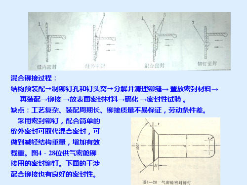
混合铆接过程: 结构预装配→制铆钉孔和钉头窝→分解并清理铆缝→ 置放密封材料→
再装配→铆接 →放表面密封材料→硫化 →密封性试验 。 缺点:工艺复杂、装配周期长、铆接质量不易保证,劳动条件差。
采用密封铆钉,配合简单的 缝外密封可取代混合密封,可 做到减轻结构重量,增加有效 载重。图4-28位供气密舱铆 接用的密封铆钉。下面的干涉 配合铆接也有良好的密封性。
总装是桨叶前段和后段件的装配。工件装配和固化都在夹具中进 行,用机械加压方法保证大梁和后段件胶粘面与弦平面垂直。
上述装配工作完成后,还要对翼尖、调整片等做架外安装和铆接, 并对表面作密封,测量扭角等。 (5)桨叶称重和平衡
旋翼各桨叶应是静平衡的,它是动平衡的必要条件。所以制造过程中一定 作好重量控制。
飞机水平测量原理: 在部件表面规定的位置,按照型架
中的专用装置标出点的记号,这些点为 水平测量点,实际上是将飞机理论轴线 转换到部件外表面,作为测量基准。测 量时,只要检查这些点相互位置的数据, 就可以确定部件相对位置的几何参数是 否符合技术条件。图4-92中,1-10各测 量点都在部件装配时定出,用水平仪将 1、2和1‘调到同一水平面内,再用经纬 仪把7、8调到一个垂直面内,然后用水 平仪、经纬仪分别测3 、 4 、 9 、 10 就可判断机身各段的同轴度、机翼安装 角、下反角等。
- 1、下载文档前请自行甄别文档内容的完整性,平台不提供额外的编辑、内容补充、找答案等附加服务。
- 2、"仅部分预览"的文档,不可在线预览部分如存在完整性等问题,可反馈申请退款(可完整预览的文档不适用该条件!)。
- 3、如文档侵犯您的权益,请联系客服反馈,我们会尽快为您处理(人工客服工作时间:9:00-18:30)。
一.整体壁板毛坯 主要为铝合金,另有钛合金、镁合金。整体壁板毛坯的主要制造方法: 热摸锻、挤压、自由锻板坯、热轧平板毛坯和特种铸造。
1.大吨位液压机和锻模生产壁板毛坯 优点:生产率高、锻件纤维组织连续,晶粒致密,强度高,可制造复杂 形状筋肋和对接接头。
热模锻毛坯接近于成品尺寸,厚度和桁 条间距误差小于0.6mm,锻造斜度小锻需要吨位极大的机床,铝合金壁 板每平方米投影面积约需3万吨压力, 精锻时要5~6万吨。且锻模制造困难、 周期长、劳动量大。如某飞机整体壁板 的锻模重量达50~60吨。 这些问题限制了热模锻方法的广泛应用。
Most authors used in their experimental study on incremental forming regular 3 axis milling machine. Figure 7 presents the incremental forming process.
characteristics of the incremental forming process are pointed out:
- the sheet is formed according to a given locus - the deformation of the sheet is point-by-point - the deformation of every step is small.
Figure 8 The control system of Dieless NC Forming machine.
Figure 9 Equipment for Dieless NC Forming process
The blank sheet is attached to a blank holder. The blank holder moves in vertical direction according to descending of Ztool and along X- and Y-planes.
An approximate deformation analysis for the incremental bulging of sheet metal using a ball roller is developed . The incremental bulging method has been applied for non-symmetric shallow shells.
(2)疲劳寿命长; (3)外形准确、表面光滑; (4)可简化整体油箱的密封,腾出最大的有效空间。 2.工艺方面: (1)简化了互换性问题、减轻了装配工作量; (2)减少模具和装配型架数量、缩短生产准备周期; (3)可采用锻、挤、轧、铸等加工方法,在大批量生产时提高生产效率。 3.存在缺点: (1)要切除大量金属,须配备大型加工设备和专用机床; (2)除热碾平板毛坯外,其他形式毛坯供应困难且费用较高; (3)从“破损”角度看,裂纹扩展速度较快,不如铆接、更不如胶接结
半开的铸型中,合拢机架使金属液面上升充满模腔,挤出多余的金 属。 特点:铸造金属的机械性能较差,但能适应复杂形状,成本低、机加 工作量小,为等强度设计提供了可能。 铸造壁板一般内外表面都铸成最后尺寸,机械加工只限于接头部分和 对外形的修光,生产效率高。
二.毛坯的校平与残余应力的消除
still some limitations with the method in geometry, product size
and surface quality.
第三章 飞机整体结构机械加工制造工艺
第一节 概述
过去飞机机体的主要结构件都是由钣金零件装配而成,而近年来随着 数控加工技术的普遍应用,整体框、梁、肋结构大量出现,同时整 体壁板结构更为常见,因此机械加工零件的比重已经超过钣金件。
平直度较高,板坯提供状态最好是上下表面预先经过铣平,并裁切 成与零件外形接近的形状; (2)加强筋不可设计成T形或比较复杂的形式; (3)加强筋最好设计成等距平行排列。
4.特种铸造制毛坯 对尺寸不大、有敞开斜角内筋,且壁板厚度大于2~4mm时,可采用
挤铸和低压铸造法加工整体壁板毛坯。 图3-5就是用挤铸法原理成批生产的铝合金导弹翼面,把金属液注入
Figure 7 Schematic diagram of the incremental sheet metal forming process
Dieless NC Forming is a cold forming technology that is developed in Japan for the needs of automotive industry. It has been commercialised by Japanese company Aimono Corporation. Dieless NC Forming is a numerically controlled incremental forming process that can form various materials into complex shapes. The method allows forming without large and expensive dies, using only a simple support tool under the formed piece. This makes the method very cost effective. Dieless NC Forming is an alternative manufacturing method to small lot production and prototyping.
Figure 10 Principal of Dieless NC Forming
Forming starts on the top of the piece, where also the support tool is placed. The Z-tool makes a round path around the support tool and after one round, lowers itself down for defined pitch and continues forming. The tool path as well as the vertical pitch are defined by the convertion software based on the CADmodel of the product. The tool changes the moving direction after each round to prevent material twisting around the Z-axis of the product. The forming process is illustrated in Figure 11.
优点: (1)厚板供应来源广; (2)且允许设计者比较自由地布置筋条和凸台; (3)准备周期短,制造精度及光洁度高。 缺点: (1)加工量大,材料利用率低(~10%); (2)需配备大型高效切削加工设备; (3)经过切削加工后,材料纤维被切断,机械性能变差; (4)机械加工中发生翘曲程度大,消除困难。 用板坯或板料加工整体壁板时,必须考虑: (1)由于机加过程通常使用真空平台来定位和夹紧板料,所以要求
2.热挤和冷挤压毛坯 优点: (1)能获得比模锻更大的壁板,因为正挤压方法在理论上不受加工厂长
度的限制; (2)与模锻相比,要求设备功率小、模具制造费用低、生产率高、材料
利用率可达70%以上; (3)挤压件尺寸精度和光洁度较好,除形状复杂部位需表面修整外,不
需进一步加工; (4)挤压时材料处于三向压应力状态,
对塑性较差的材料加工意义很大。 缺点: (1)挤压毛坯只能是等剖面有纵向加强筋 或桁条的整体壁板; (2)毛坯仍受挤压设备及校平设备限制; (3)模具寿命低。
挤压法制造整体壁板的两种方法: (1)先挤出带筋的筒形(U或V形)毛坯,然后沿轴线剖开展平
优点:能挤出较宽的壁板; 缺点:展开工序较为复杂。 (2)直接挤出带筋的平直壁板 缺点:宽度尺寸不大。 挤压毛坯在淬火后一般需要在拉伸机上校正,以消除壁板在挤压及淬火 过程中产生的纵向波纹度和横向翘曲(“马刀形”变形),消除内应力, 然后在滚床(水压机)上进行校平。 3.自由锻毛坯和热轧平板 实质上是在一块经过自由锻造 初步接近于零件形状的立体形状 毛坯或在一块轧制的厚板上“雕刻” 出所需零件的形状来。
由于成形工具头半径远远小于板料的尺寸,所以每次产生的变形仅 集中在成形球头的周围,是靠变形的积累而得到整体变形的。变形区材 料受双向拉应力,导致板料变薄,极限情况就是产生拉伸失稳而破裂。 (3)重要的研究方向
单点渐进成形法要解决的重要课题是成形工艺规划和加工路径的设 计问题。 (4)优点
非常适合新产品的快速开发、设计验证和小批量、多品种产品的生 产,并且能成形比较复杂、延伸率更高的零件。
Some machines only allow moving along X-plane. The support tool is placed under the workholder and the blank sheet is moulded against the support tool. The Z-tool is computer controlled. The forming principle is shown in Figure 10.
Figure 11 Dieless NC forming process
(5)Limitations
Dieless NC Forming is suitable for one-piece and low volume production. It can also be used as a prototyping method for sheet metal products produced in large series. The maximum production capacity of the Dieless NC Forming machine is about 500 pieces a month, varying widely on the size and geometry of formed products. The method is slow when compared to for example deep drawing, and it is not competing with traditional forming methods. There are
